
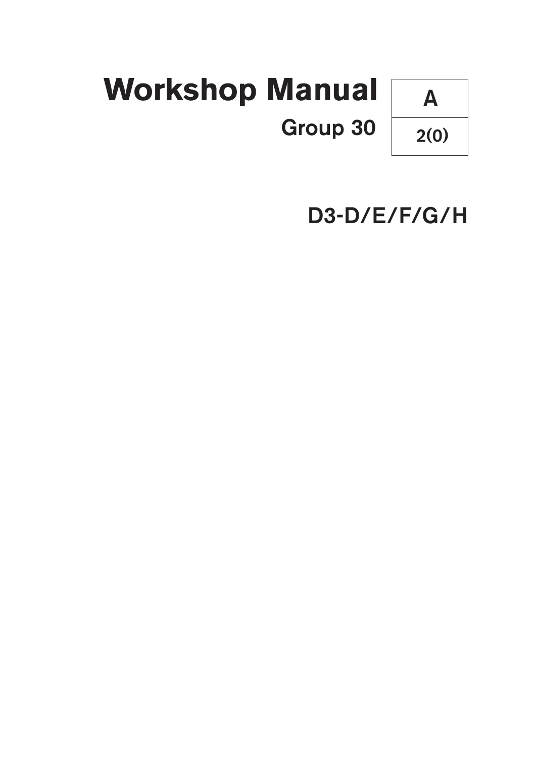
Volvo Penta D3-D, D3-E, D3-F, D3-G, D3-H Marine Engines Group 30 Electrical Workshop Manual
Original price was: $34.95.$21.95Current price is: $21.95.
Factory Group 30 electrical system workshop manual for Volvo Penta D3-D, D3-E, D3-F, D3-G, and D3-H marine diesel engines. Provides exhaustive diagnostic fault code tracing, Bosch EDC17 engine management pinouts, sensor testing data, and complete wiring schematics.
Description
Complete Electrical System Workshop Manual for Volvo Penta D3 Marine Diesel Engines
The Volvo Penta D3-D, D3-E, D3-F, D3-G, D3-H Marine Engines Group 30 Electrical Workshop Manual is the official workshop reference for qualified technicians and marine engineers servicing modern electronic diesel control installations. Centered entirely on the electrical architecture and engine software management of the 5-cylinder Volvo Penta D3 generation, this technical publication provides complete diagnostic pathways, electrical specifications, component locations, harness pin assignments, and system-level schematics. Whether diagnosing intermittent CAN bus dropouts, pinpointing faulty sensor readings, or re-calibrating replacement common rail injectors, this manual delivers the factory-level data required for accurate troubleshooting.
File Details
- Manual Type: Workshop Manual (Group 30 Electrical System & Fault Tracing)
- Brand: Volvo Penta
- Engine Models Covered: Volvo Penta D3-D, D3-E, D3-F, D3-G, and D3-H
- Publication Number: 47701609
- Edition / Issue Date: 09-2019
- Language: English
- Page Count: 160 pages
- File Format: High-resolution PDF
Electronic Engine Control & System Architecture
Volvo Penta D3-D, D3-E, D3-F, D3-G, and D3-H marine diesel engines rely on the advanced Bosch EDC17 Engine Electronic Control Unit (EECU), working in tight coordination with the Powertrain Control Unit (PCU) and Helm Station Control Unit (HCU). This workshop guide provides comprehensive functional overviews of how the EECU gathers operating data, regulates high-pressure rail delivery, drives the variable geometry turbocharger (VGT), and oversees the charging cycle. Understanding these interacting control circuits is critical for troubleshooting driveability faults, engine protection derates, and electronic communication codes across the SAE J1939 CAN network and LIN bus circuits.
IMAGES PREVIEW
Chapters Covered
- General Information: Publication overview, certified engine requirements, service standards, tightening torques and angle tightening rules, lock nut reuse guidelines, bolt strength grades, RTV and anaerobic sealing compounds, fluorocarbon rubber handling precautions.
- Specifications, Electrical: Comprehensive technical data for intake air pressure/temperature sensors, camshaft Hall effect sensor, coolant temperature thermistor, fuel temperature thermistor, inductive crankshaft sensor, ultrasonic oil level/temperature sensor, linear oil pressure and rail pressure sensors, water-in-fuel switch, 14V/150A alternator, 12V/2.2kW starter motor, circuit breaker and fuse ratings, and electric fuel pump current/flow rate curves across operating voltages.
- Safety and Other Instructions: Workshop safety protocol, fire prevention, personal protective equipment, fuel line handling restrictions, battery handling, and high-pressure fuel spray safety.
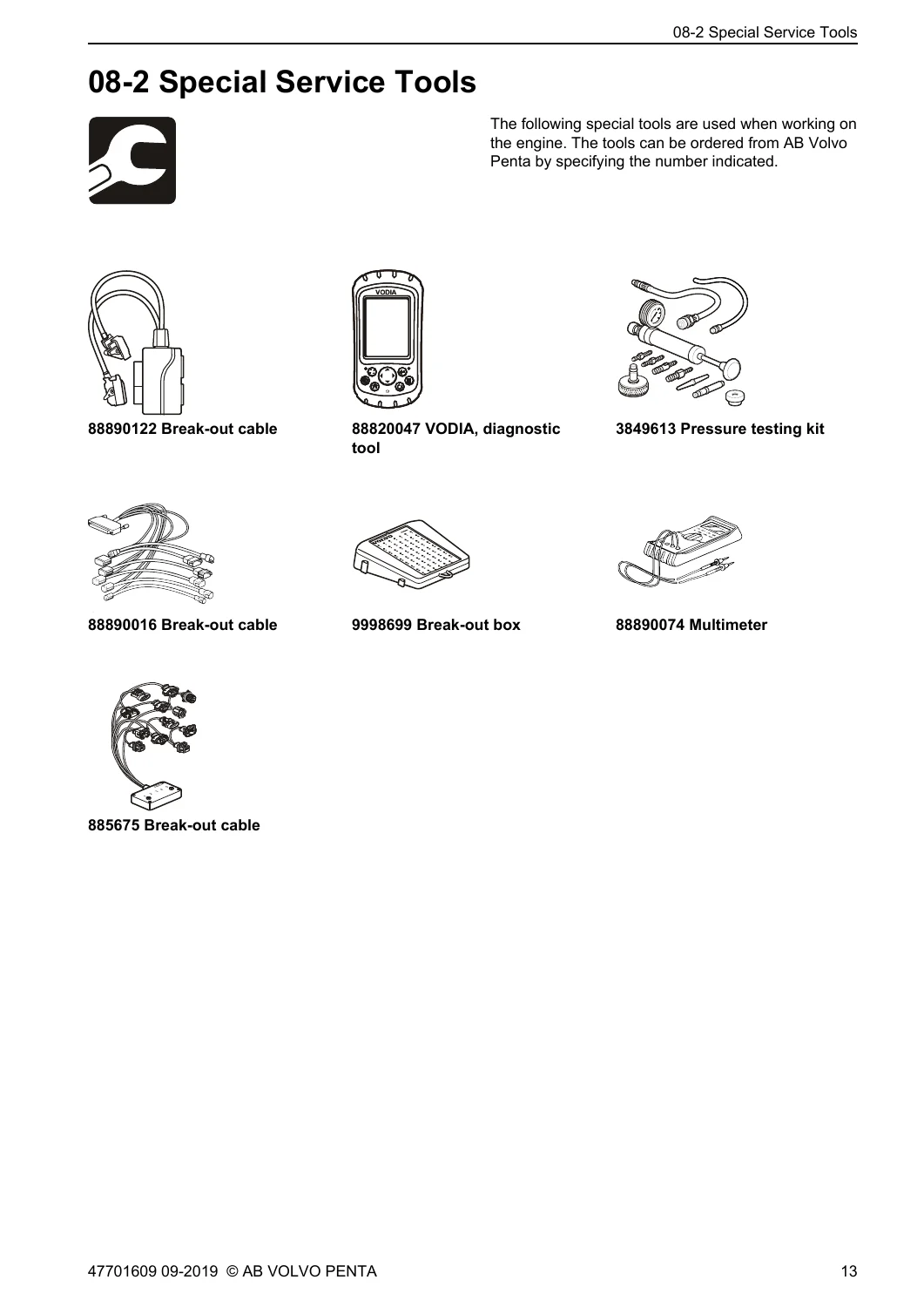
- Special Service Tools: Dedicated Volvo Penta service equipment including VODIA diagnostic tool (88820047), multimeters (88890074, 9812519), break-out cables (885675, 88890016, 88890122), break-out box (9998699), and vacuum/pressure test kit (3849613).
- General, Complete Vehicle Software: Component location photography and line art, detailed component descriptions, electrical welding rules, EECU/PCU bus communication fault tracing (120-ohm terminating resistance checks), harness shake tests, open/short circuit isolation, starter motor voltage drops, charging system diagnostics, alternator regulator replacement, rail pressure voltage lookup tables, and VODIA ECU programming procedures.
- Fault Tracing & Fault Codes: Diagnostic methodology, active vs. inactive fault code statuses, Failure Mode Identifier (FMI) table, and step-by-step diagnostic routines for all MID 128 fault codes covering inlet air heaters, throttle pedal position, oil and fuel temperature/pressure, boost pressure, VGT actuator, starter and fuel pump relays, sensor 5V power supplies, internal ECU faults, injector amplifier stages, MPROP valves, and PCV pressure release valves.
- Sensor & Actuator Bench Measurements: Pin-by-pin breakout box tables, resistance curves vs. temperature for NTC thermistors, output voltage verifications, injector coil resistance tests, and 8-character piezo injector trim code programming with VODIA.
- Wiring Diagrams: Glow plug sub-circuits, 1.5-pole electrical schematics, and complete engine harness wiring diagrams for D3-D/E/F, D3-G, and D3-H configurations detailing every splice, connector, and terminal pin assignment.
Rather than providing generalized electrical theory, this document arms marine service technicians with hard test parameters, terminal-level pinouts, and exact expected values (such as sensor resistance tables from 0°C to 100°C) to confirm component health before removing or replacing costly electronic units.
Comprehensive Fault Code Tracing (MID 128)
A primary strength of the Volvo Penta D3-D, D3-E, D3-F, D3-G, D3-H Marine Engines Group 30 Electrical Workshop Manual is its exhaustive fault code library. Every entry is structured with exact conditions for code generation, alarm panel indicators, engine symptoms (including limp-home and engine protection derates), root causes, and ordered step-by-step repair actions. Critical diagnostic sequences detailed in the manual include:
- Fuel System Management: Fault tracing for rail pressure regulation errors (PID 164), fuel temperature anomalies (PID 174), MPROP proportional valve circuits (PSID 96), and rail-mounted Pressure Control Valve failures (PSID 97).
- Piezoelectric Injectors: Circuit checks for SIDs 1 through 5, injector amplifier bank diagnostics (PSID 54 and PSID 55), coil resistance verification (180 kΩ), and VODIA parameter trim coding.
- Air & Turbo Control: Diagnosing intake manifold temperature (PID 105), boost pressure plausibility (PID 106), VGT vacuum actuator solenoid faults (SID 27), and mechanical VGT guide rail lever movement timing tests.
- Engine Timing & Speed: Flywheel inductive sensor waveforms (SID 22), camshaft Hall effect signal synchronization (SID 21), and crank-to-cam timing discrepancy faults.
- Power Distribution & Relays: Battery potential monitoring (PID 158), main relay holding circuits (SID 218), fuel supply pump actuator relay (SID 78), starter motor engage relays (SID 39), and dual internal 5V reference rails (SID 211 and SID 212).
Technical Service Capability & Instant Delivery
Acquiring this genuine factory workshop manual enables technicians, marine mechanics, and skilled boat owners to perform trade-standard diagnostics and repairs on Volvo Penta D3 common rail systems. Having access to precise sensor resistances, circuit diagrams, and ECU pinouts eliminates guesswork, preventing misdiagnosis and safeguarding sensitive electronic modules against improper testing methods or over-voltage damage. Delivered as an instant PDF download immediately upon checkout, this comprehensive workshop document contains no shipping delays and can be accessed instantly on workshop laptops, tablets, or mobile devices in the engine bay, or printed out for immediate bench reference.
Reviews
There are no reviews yet.