
Volvo Penta EVC-C1 C2 Workshop Manual Group 30 Electrical System – PDF
Original price was: $39.95.$24.95Current price is: $24.95.
Complete Volvo Penta Group 30 Electrical System workshop manual for EVC-C1/C2 installations. Full fault tracing for HCU, PCU, CPM and SUS nodes, wiring diagrams, special tools and pin configurations. Doc 7749172, 316 pages, English.
Description
Volvo Penta EVC-C1/C2 Group 30 Electrical System Workshop Manual
This is the complete workshop documentation for the electrical side of the Volvo Penta EVC (Electronic Vessel Control) platform, published by AB Volvo Penta under document number 7749172, English edition 08-2009. Where a general engine manual stops at the harness, this Volvo Penta EVC-C1/C2 Workshop Manual Group 30 Electrical System keeps going: into the nodes themselves, into the CAN and J1587 buses that link them, and into the fault-code logic that tells you which one is lying to you.
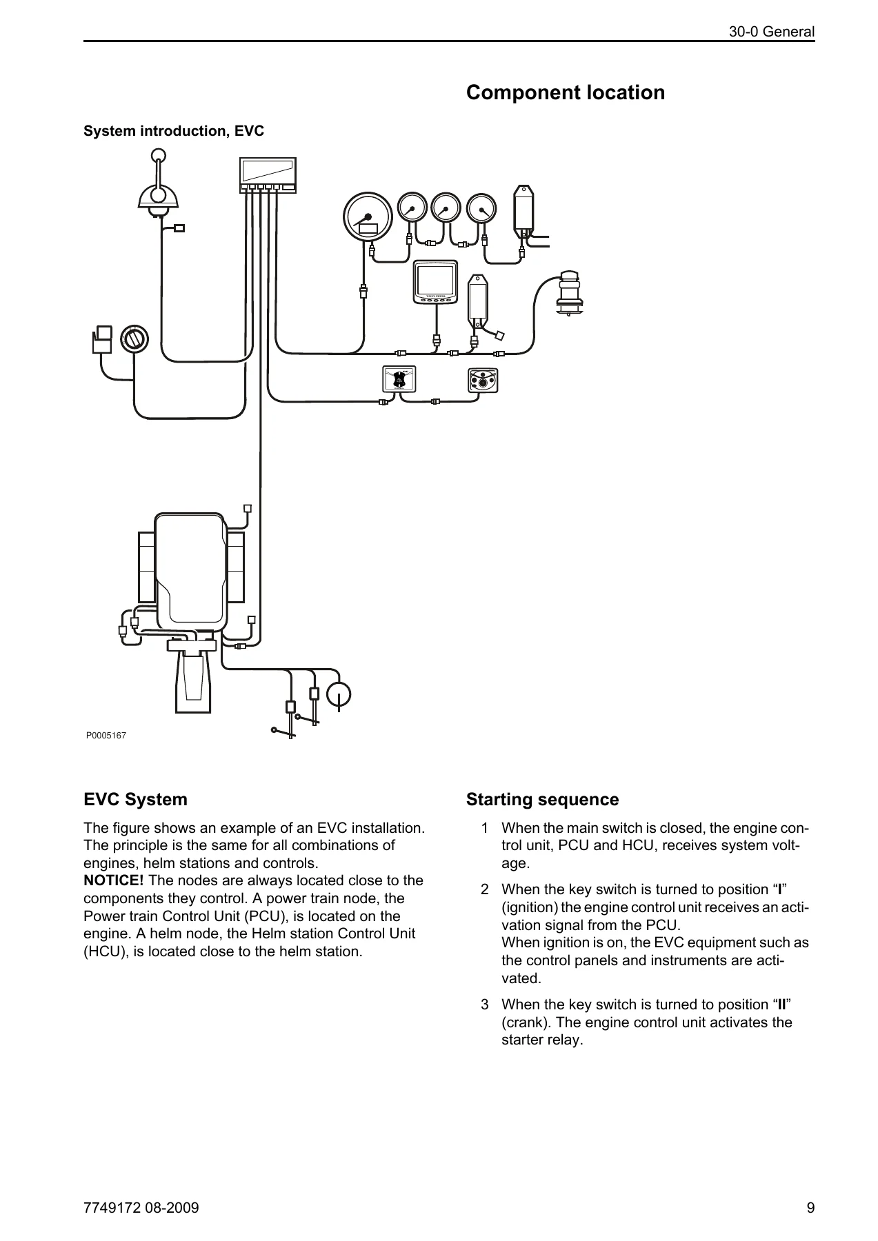
The EVC system is a distributed network. Instead of one central brain, it spreads control across several electronic units placed where the work actually happens — the PCU (Powertrain Control Unit) on the engine, the HCU (Helm station Control Unit) at the helm, the SUS (Servo Unit Steering) in the drive leg, and the CPM (Corrosion Protection Module) for the Active Corrosion Protection system. This EVC-C1/C2 workshop manual treats each of those nodes as its own serviceable subject with its own fault-code set, while never losing sight of the network they form together.
File Details
- Manual type: Workshop Manual / Service Manual
- Brand: Volvo Penta
- System covered: Group 30 — Electrical System, EVC-C1/C2
- Document number: 7749172
- Edition / date: 08-2009
- Language: English
- Page count: 316 pages
- File format: PDF
- Applicable engines: D4 and D6 diesel installations, plus EMS-managed gas engines (see wiring diagrams)
Chapters Covered
- 00-0 General — general information, spare parts policy, certified engines, about this workshop manual, repair instructions and mutual responsibility
- 05-1 Safety Instructions — safety information and the DANGER / WARNING / CAUTION / IMPORTANT priority structure used throughout
- 08-2 Special Service Tools — breakout box 885675, crank tool 3809570, brake release switch 3812541, VODIA 3838619, multimeter 9812519, breakout box 9998699, breakout cables 88820040 and 88890016
- 30-0 General — EVC system design and function, distributed node architecture, engine speed and gear shifting, engine synchronizing, Easy Link instruments, EVC display, fuel level, boat speed, fresh water level, rudder indicator, multi sensor, alarm display, component location, starting sequence
- Node identification and CHASSIS ID matching across PCU, HCU, SUS and CPM
- Solenoid valves — forward/reverse gear shifting and trolling valve
- Interface bracket connectors, lever control, potentiometer, neutral switch, gear shift actuators (gas and diesel)
- General advice on working with EVC engines, electric welding procedure, fault tracing of cables and connectors, manual CAN bus resistance measurement
- 30-2 Fault Tracing — FMI table and SAE-standard failure mode identifiers
- MID 164: HCU — transmission neutral switch, SAE J1939 data link, program memory, J1708/J1587 data link, calibration memory EEPROM, controller 1, sport fish panel, power trim control signal, lever 1 and lever 2 position relative to potentiometer supply, lever potentiometer supply, EVC bus power input, key supply, main panel supply, steering wheel position, external lever, joystick, joystick buttons, display, menu control knob, panel buttons, multisensor, lever potentiometer, helm station transfer, single lever control, incompatible EVC software, lever detection and calibration faults, EVC bus network configuration, start and stop switch, steering wheel data link, module, brake and controller, rudder angle, steering position divergence, autopilot, incompatible helm station software and data links
- MID 187: PCU — fuel level, transmission oil pressure, gearbox oil temperature, output shaft speed, EVC bus power input, shift actuator position and potentiometer supply, transmission sensor supply, power trim position and potentiometer supply, SAE J1939 data link, program memory, J1708/J1587 data link, calibration memory EEPROM, controller 1, incompatible engine type, EVC bus power outputs, primary and secondary transmission solenoids, gear actuator direction, power trim motor UP and DOWN, EVC bus communication with active helm, shift actuator potentiometer and data links
- MID 200: CPM — active anode potential, passive anode potential, polarization potential, polarization current, SAE J1939 data link, program memory, calibration memory EEPROM, controller 1
- MID 250: SUS — battery potential, ECU temperature, EVC bus power input, steering wheel position, rudder angle, servo motor temperature, SAE J1939 data link, program memory, calibration memory EEPROM, controller 1, EVC bus network configuration, EVC bus power output, servo motor, rudder brake, EVC bus communication, detection faults and data links
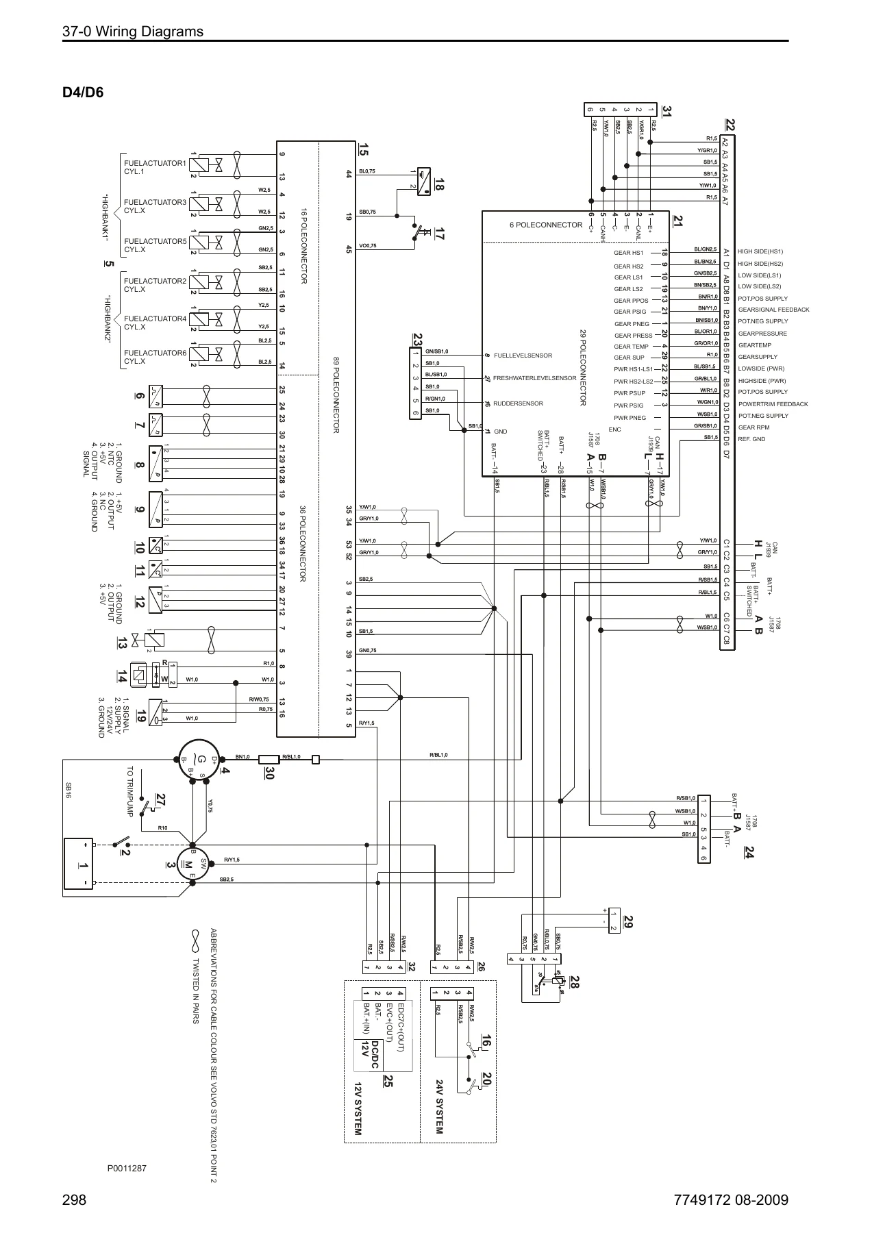
- 37-0 Wiring Diagrams — EVC single installation with main and secondary helm station, D4/D6 and EMS system wiring schedules, cable colour codes to Volvo STD 7623,01
- Pin configurations — PCU connectors X2 and X3, HCU connectors X2 through X8, SUS connector, CPM multilink / data link / shield unit, 88890016 breakout cable and measurebox pin numbering
- 39-0 General — alphabetical index and references to Service Bulletins
Read as a whole, the manual gives a technician a complete working method for the EVC electrical system rather than a pile of disconnected procedures. It starts from how the distributed network is meant to behave when everything is correct, then hands you the fault-code tables, the connector pinouts and the measurement values that let you prove where it has stopped behaving correctly.
What the Fault Tracing Section Actually Gives You
The fault-code chapters are the core of this manual and they are written the way a diagnostic technician works: fault code first, then conditions, then possible reasons, then suitable actions. Each entry carries the FMI designation and its SAE meaning, the fault indication shown to the operator, the symptoms the boat exhibits, the relevant cable description, and the measurement points with nominal values.
Because the system is split across several nodes, the manual is explicit about which node reports what. HCU codes are read from the helm side, PCU codes from the driveline, and in twin installations the port and starboard networks are diagnosed separately. The manual states plainly that on a twin-engine boat, VODIA connected to the port network will only display fault codes from the port PCU, and the same applies to starboard. That single detail saves hours of chasing a fault on the wrong engine.
It also covers the practical realities of the job: the correct way to put an HCU into service mode so VODIA can read it, why only one HCU can be in service mode at a time, what auto configuration does and when it must be performed, and the 28-day reporting requirement after ECU programming.
Measurements, Connectors and Wiring Diagrams
Volvo Penta Special Tools are called out by part number at every measurement step, so you know whether a reading can be taken with the multimeter alone or whether the breakout box and adapter cable need to be in line. Resistance checks, voltage checks and VODIA log tests are given side by side, with nominal values stated in ohms, volts and battery-voltage multiples.
The wiring diagram section covers an EVC single installation with a main and secondary helm station, and the D4/D6 and EMS system schedules run across several pages with cable colours and cross-sectional areas printed on every conductor. The pin configuration tables then translate those diagrams into the physical connector: what sits on PCU X2 and X3, what each of the eight HCU connectors carries, and how the CPM’s multilink, data link and shield unit pins are arranged.
Who This Manual Is Written For
The manual states its own audience: Volvo Penta workshops and qualified personnel, on the assumption that the reader has a fundamental knowledge of the product and can carry out mechanical and electrical work to trade standard. It is not a beginner’s guide to marine electrics — it is the reference a marine electrician or Volvo Penta-trained technician reaches for when an EVC fault code appears and the boat needs to go back in the water working.
It is equally useful for the technically capable owner of a D4 or D6 installation who wants to understand what the alarm display is actually telling them before calling anyone out, and for anyone maintaining a vessel where the helm, engine and drive leg all talk to each other over the same network.
What You Can Do With This Volvo Penta EVC-C1/C2 Workshop Manual Group 30 Electrical System
With this manual on hand you can decode an EVC fault code down to the node that set it, follow the fault tracing path for that specific code, and measure the circuit at the points the manual specifies instead of guessing. You can check and calibrate lever potentiometers, verify neutral switch operation, test gear shift actuator motors and feedback signals, check transmission oil pressure and temperature sensors against their resistance curves, test power trim potentiometer supply and motor direction outputs, and work through the resolver and servo motor diagnostics on an IPS driveline.
You can also confirm the network itself is healthy — measuring CAN H to CAN L resistance, checking EVC bus power supply at both ends of a cable, verifying that the CHASSIS ID on every node matches the engine, and knowing what the system will and will not do when a node has been replaced and not yet programmed.
Getting this right matters because the EVC system is not forgiving of shortcuts. The manual repeatedly warns that system voltage must be cut at the main switch before control module connectors are disconnected or connected, that the main switch must never be opened while an engine is running, that only batteries may be used for start help because a help-start device can produce a voltage high enough to destroy the control unit, and that a battery cable must never be undone with the engine running. It also spells out the correct procedure for electric welding on the boat: cut the current, undo the connector from the engine control unit, disconnect the alternator, and connect the welder earth clamp to the component being welded — never to the engine or anywhere current can pass through a bearing.
The manual is also direct about the parts side of the job. Spare parts for electrical and fuel systems are subject to national safety standards, Volvo Penta Original Spare Parts meet those standards, and damage caused by non-approved parts is not covered by any warranty undertaking.
IMAGES PREVIEW
Delivery is instant. The PDF is available for download immediately after payment, with no shipping and no waiting. It opens on any device — laptop, tablet or phone — and every page can be printed for use in the engine bay or at the helm, which is where a wiring diagram is actually needed.
Reviews
There are no reviews yet.