
Volvo Penta EVC-E Group 30 Electrical System Workshop Manual 2015
Original price was: $39.95.$23.95Current price is: $23.95.
Volvo Penta EVC-E Workshop Manual for Group 30 Electrical System, publication 47703793 dated 09-2015. Full EVC fault code diagnosis for HCU, PCU, MGX, ICM, CPM, SUS and SCU nodes, measurements, VODIA log parameters, circuit descriptions and wiring diagrams.
Description
Volvo Penta EVC-E Group 30 Electrical System Workshop Manual
This is the Volvo Penta workshop manual for Group 30, the electrical system of the EVC-E platform (Electronic Vessel Control generation E). Publication number 47703793, English edition dated 09-2015. It is a complete electrical service document covering how the EVC system is designed, how each node behaves, how to fault trace the network, and how to test every sensor, solenoid, actuator and bus wire with a multimeter and the VODIA diagnostic tool.
File Details
- Manual type: Workshop Manual (Service Manual), Group 30 Electrical System
- Brand: Volvo Penta
- System: EVC-E (Electronic Vessel Control, generation E)
- Publication number: 47703793
- Edition / date: 09-2015
- Language: English
- Page count: 388 pages
- File format: PDF
Chapters Covered
- 00-0 General – General information, spare parts, certified engines, about this workshop manual
- 05-1 Safety Instructions – Danger, Warning, Caution, Important, Notice; battery and electrical safety
- 08-2 Special Service Tools – Break-out cables, break-out box, VODIA diagnostic tool, multimeter, crank tool, brake release switch, mounting tool
- 30-0 General – Design and Function: EVC system overview, distributed nodes, CAN bus, identification of nodes by CHASSIS ID
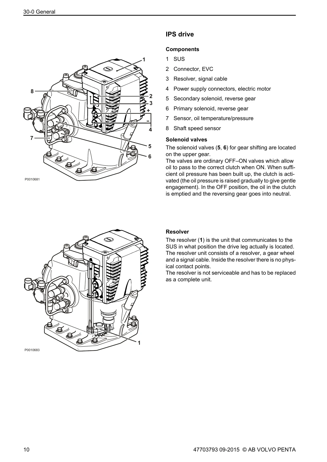
- Component description – HCU / control lever, PCU, SUS, SCU, CPM, inboard solenoid valves, IPS drive components, resolver, shift actuators, Aquamatic solenoids, hydraulic valve plate, DPH and DPS drive position sensors
- Repair Instructions – General advice on working with EVC engines, electrical welding, servo motor dismount from interceptor, interceptor shaft torque and movement range checks, servo motor function checks
- Volvo Penta Glass Cockpit – Concerned products, service and support setup, fault tracing, software versions, power issues, button functionality, touchscreen calibration, Garmin Marine Network and NMEA 2000 device issues, mapping updates, service request hand-over, warranty and reimbursement
- 30-2 Fault Tracing – General fault tracing in the EVC system, fault tracing of cables and connectors, fault tracing of the EKS system, DTC categories
- Fault Codes – MID 164: HCU; MID 130: MGX; MID 187: PCU; MID 194: ICM; MID 200: CPM; MID 250: SUS; MID 250: SCU
- Measurements – Schematic symbols, checking the EVC bus, diesel key switch diode, multilink bus, aux bus, DPS gateway connection, HCU to AKI signals, key switch to AKI signals, steering control bus, fuel level sensor, transmission oil pressure and temperature sensors, propeller shaft speed sensor, shift solenoid, slip solenoid, PCU-EECU wiring, gear shift actuator potentiometer, actuator / shift solenoid output driver voltage, clear wake exhaust valve, resolver, drive position sensor, power trim potentiometer, autopilot gateway LED, power trim control signal, cranking the IPS unit, hydraulic steering oil temperature sensor, steering / service solenoid, CPM signals, ICM servo unit wiring, transmission oil quality sensor, LED check of an EVC gateway
- VODIA Log Parameters – MID 164: HCU, MID 187: PCU, MID 200: CPM, MID 250: SCU logging parameters and their normal values
- Circuit / Component Descriptions – EVC bus, A-CAN, hydraulic oil temperature sensor, steering solenoids, service valve, multilink hub, drive position sensors, key panel / LIN bus, steering control bus, fuel level, multilink bus, aux bus, transmission oil and temperature, slip, PCU-EECU wiring, gear shift actuator, gear shift solenoids, Power Trim, Clear Wake Exhaust System, DPS gateway, joystick, NMEA, VP autopilot connection, CPM, CPM configuration
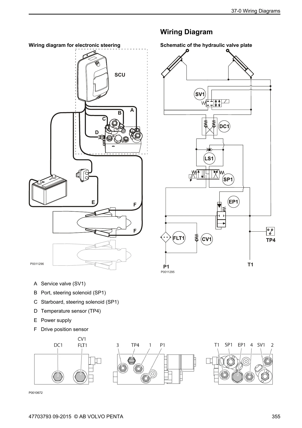
- 37-0 Wiring Diagrams – Break-out box pin configuration, PCU pin configuration, HCU pin configuration, SUS pin configuration, CPM pin configuration, SCU pin configuration, electronic steering wiring diagram, multilink T split, multilink hub, aux bus Y-splits, e-key harnesses, E-key functionality, EVC installations, PCU outputs for AQ drive D4/D6, IPS1, D4/D6, AQ drive D3, HS reverse gear, IPS2/IPS3, ZF reverse gear, MGX reverse gear
- 39-0 General – Alphabetical index, references to service bulletins, report form
What makes this document genuinely useful is the pairing of theory with procedure. The design and function chapter explains how each node in the distributed EVC network is programmed for a specific engine and how the CHASSIS ID on the node label must match the engine and SUS / SCU labels. The fault tracing chapters then turn that into an ordered diagnostic process. Every fault code entry is presented in the same disciplined format: FMI number, DTC category, fault code explanation, alarm status, whether the code is stored in memory, symptom, conditions for the code to set including the DTL time, possible reason, suitable action, logging parameter and the measurement section to use. That structure means a technician reading MID 187, PSID 20 on a primary shift solenoid can move straight from the code to the switching test between primary and secondary solenoids described in the measurement chapter.
The measurement chapter is where the manual earns its place on the bench. Each procedure lists the special tools required, the break-out box pins to probe, the schematic of the connector viewed from the cable side, and the expected reading. Examples include the EVC bus check between X2:1 and X2:3 with a nominal battery voltage and roughly 4 V on EVC bus L and 1 V on EVC bus H, the multilink bus check on X5, the aux bus check across PCU pins 38, 40, 63 and 14, the steering control bus check on X8, and the resolver resistance table at 37 ohm between pins 1 and 2 and 100 ohm between pins 3-4 and 5-6. Transmission oil temperature is supported by a full resistance table from 4930 ohm at 0 degrees C down to 104 ohm at 100 degrees C, and the hydraulic steering oil temperature sensor has its own table from 9400 ohm at 0 degrees C to 60 ohm at 140 degrees C.
What This Manual Lets You Do
With this Volvo Penta EVC-E Group 30 Electrical System workshop manual you can read, interpret and clear diagnostic trouble codes across all seven node types in the network, including HCU helm control units, PCU powertrain control units, MGX transmissions, ICM interceptor control modules, CPM corrosion protection modules, SUS steering unit servos and SCU steering control units. You can trace a fault from an alarm status on the display back through the wiring to the exact pin, confirm it with a resistance or voltage measurement, and decide whether the fault sits in the harness, the sensor, the solenoid or the control unit itself.
Beyond code reading, the manual supports configuration and calibration work that goes wrong in the field. It explains auto configuration failures, incompatible chassis ID mismatches between HCU, PCU and SUS / SCU, incompatible EVC software between nodes and the reprogramming actions that resolve each one. It covers lever calibration faults, lever travel calibration value out of range, neutral switch detection failure, joystick calibration and steering position divergence between drivelines. It also documents the CPM configuration rule that the corrosion protection module must be installed and auto configured to the port side network, with a VODIA procedure to check and change the CPM chassis ID.
The wiring diagram chapter at the back gives the full PCU, HCU, SUS, CPM and SCU pin configurations alongside the PCU output diagrams for each drive family, so harness repair and connector replacement can be done against the correct pin rather than by guesswork. Electrical welding precautions, main switch isolation and the rule against disconnecting battery cables with the engine running are set out in the repair instructions to protect the control units during service.
Why the Correct Procedure Matters
EVC-E is a distributed network. A single open circuit on one bus wire, a shorted solenoid, a weak battery during cranking or an old software version in one node can set codes in several other nodes at once, and the symptom you see on the display is often not the cause. The manual repeatedly directs you to look for the root cause code before acting on secondary codes, and to verify wiring and connector contact pressure before replacing hardware. Following that sequence prevents unnecessary replacement of control units and sensors, and it prevents a calibration from being written against a fault that is still present.
IMAGES PREVIEW
Instant PDF Delivery
The manual is supplied as an instant-download PDF. There is no shipping and no waiting. Once payment is complete the file is available immediately, and it can be viewed on a workshop PC, laptop, tablet or phone, or printed page by page for use at the engine while the harness is open. Search and zoom make it practical to move between a fault code entry and the matching measurement procedure without losing your place on the boat.
Reviews
There are no reviews yet.