
Volvo Penta EVC-D Electrical System Workshop Manual Group 30 – PDF Download
Original price was: $39.95.$24.95Current price is: $24.95.
Volvo Penta Workshop Manual Group 30 Electrical System EVC-D – 354-page electrical workshop manual covering the EVC-D distributed control system, PCU, HCU, SUS, SCU and CPM nodes, fault codes with FMI tables, break-out box measurements, VODIA log parameters, pin configurations, wiring diagrams and transmission cables.
Description
Volvo Penta EVC-D Electrical System Workshop Manual – Group 30
This is the Volvo Penta Workshop Manual Group 30 Electrical system EVC-D, the electrical-system volume of the Volvo Penta workshop literature for boats running the EVC-D electronic vessel control platform. Document number 47701823, edition dated 03-2023, published by AB Volvo Penta, 354 pages, English language. It covers the EVC-D distributed electrical architecture end to end: the nodes that make up the network, how they talk to each other, what happens when they stop talking, and how to measure your way to the answer.
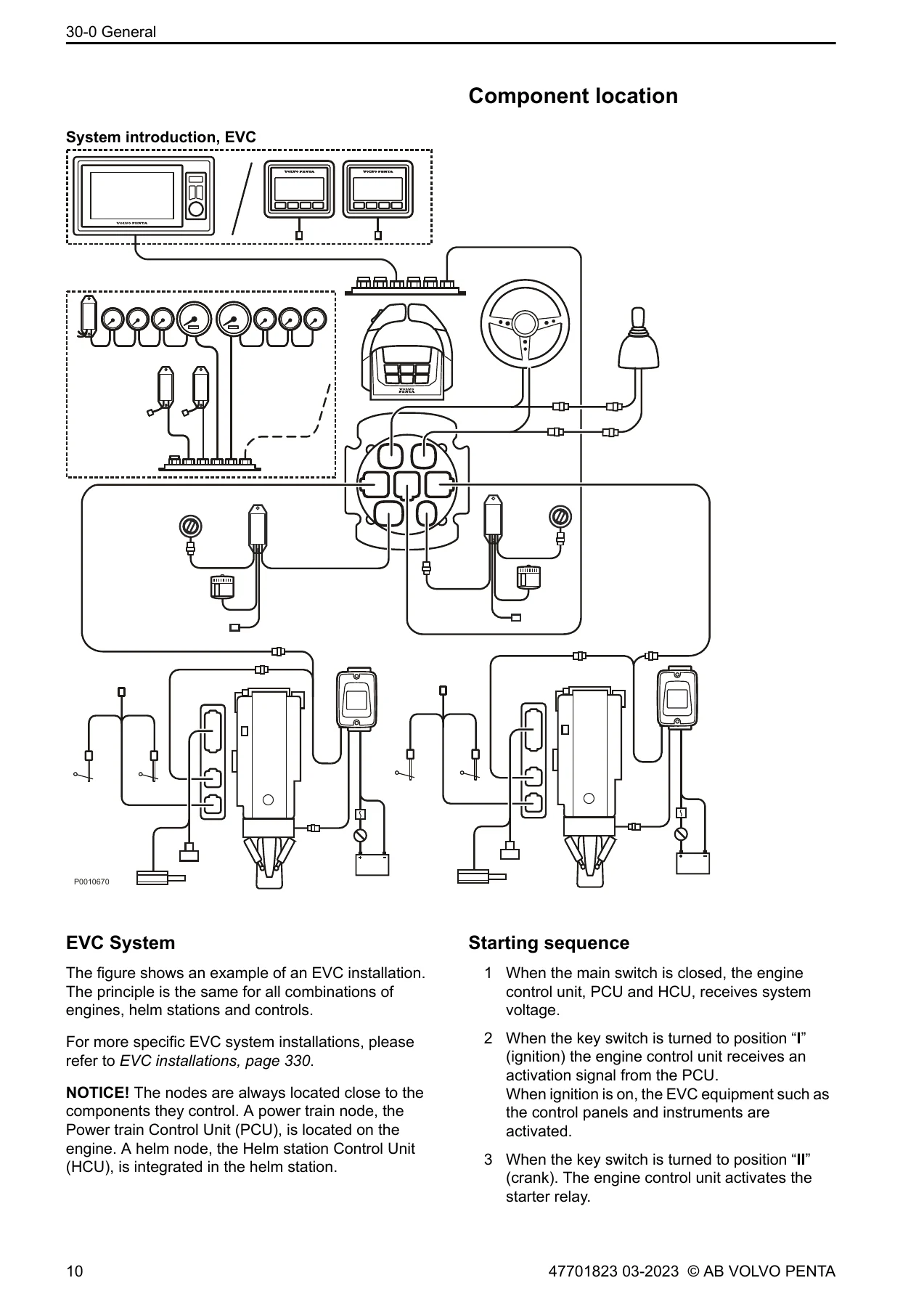
EVC-D is a distributed system. Instead of one central box, the boat carries several small electronic units placed near the components they control. This manual treats each of them in turn: the Powertrain Control Unit (PCU) on the engine, the Helm station Control Unit (HCU) built into the control lever, the Servo Unit Steering (SUS) in the IPS drive leg, the Steering Control Unit (SCU) mounted near the transom shield, the Corrosion Protection Module (CPM) for the Active Corrosion Protection system, and the MGX transmission controller. Between them they handle electronic engine speed and gear shifting, engine synchronising, Easy Link instruments, the EVC display, fuel and fresh water level, rudder indication and multi-sensor data.
File Details
- Manual type: Workshop Manual (Service Manual)
- Brand: Volvo Penta
- System covered: EVC-D (Electronic Vessel Control generation D)
- Group: 30 Electrical system
- Document number: 47701823
- Edition / date: 03-2023
- Publisher: AB Volvo Penta
- Language: English
- Page count: 354 pages
- File format: PDF
Chapters Covered
- 00-0 General – general information, replacement parts, certified engines, colours and symbols used in images, safety information
- 08-2 Special Service Tools – 885675 break-out cable, 3809570 crank tool, 3812541 brake release switch, 88820047 VODIA diagnostic tool, 9511355 break-out cable, 9998699 break-out box, 88820040 / 88890016 / 88890161 break-out cables, 88890074 multimeter
- 30-0 General – Design and Function; EVC system overview; engine speed and gear shifting; engine synchronising; instruments and Easy Link; display; fuel level, boat speed, fresh water level, rudder indicator and multi-sensor options; alarm handling display; component location; starting sequence; PCU, SCU, CPM, drive position sensor (DPH/DPS), SUS, resolver, hydraulic valve plate, transmission solenoid valves, interface bracket, HCU/control lever, actuator; Repair Instructions; malfunctions and fault code information (MID, PID, PPID, SID, PSID, FMI table); electrical welding precautions; reprogramming a control unit; programming an empty control unit; checking instruments
- 30-2 Fault Tracing – general fault tracing in the EVC system, visual connector checks, CAN bus and multilink resistance measurement; fault codes by node (MID 130 MGX, MID 164 HCU, MID 187 PCU, MID 200 CPM, MID 250 SUS and SCU) with FMI, symptom, conditions and suitable action; Measurements section; VODIA Log Parameters
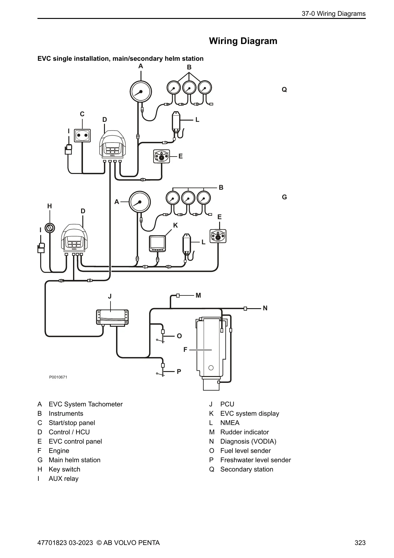
- 37-0 Wiring Diagrams – break-out box pin configuration, PCU X2 and X3 pin configuration (engine with reverse gear and engine with sterndrive), HCU X2/X4/X5/X8 pin configuration, SUS pin configuration, CPM pin configuration, SCU pin configuration, EVC single installation wiring diagram, electronic steering wiring diagram, hydraulic valve plate schematic, D4/D6, D3 Aquamatic, IPS and IPS2/IPS3 installations
- 37-1 Cables – transmission cables with and without transmission interface, AQ cable, IPS cable, IPS2/IPS3 cable, HS cable
- 39-0 General – index and references to service bulletins
What the manual gives a technician is a complete diagnostic method rather than a pile of diagrams. Every fault code entry is broken down the same way: what the code means, the alarm status it raises, the symptoms the operator will notice (gear to neutral, cranking disabled, limp home speed, low-speed limit, steering disabled), the conditions that set the code, the likely causes, and a numbered list of suitable actions. The Measurement section then backs that up with the actual instrument readings – nominal values for the EVC bus, multilink bus, DPS bus, steering control bus, key switch to AKI signals, HCU to AKI LIN signals, fuel level sensor, transmission oil pressure and temperature sensors, propeller shaft speed sensor, shift and slip solenoids, PCU-EECU wiring, gear shift actuator potentiometer, actuator and shift solenoid output driver voltage, clear wake exhaust valve, resolver, drive position sensor, powertrim potentiometer and control signal, hydraulic steering oil temperature sensor, steering and service solenoids, and CPM anode signals.
Systems and Components Documented
The electrical content is organised around the nodes and what hangs off them. On the driveline side the manual covers the PCU and its X2 data link and X3 engine/transmission connectors, the CAN link to the engine ECU, the ignition output, the J1587 diagnostic bus, gearshift control outputs, trolling control, fuel level input, water level input, rudder indicator input and the reversing gear oil pressure and temperature inputs. Transmission coverage includes primary and secondary shift solenoids, the slip or low-speed solenoid, propeller shaft speed sensing for both inboard inductive sensors and IPS active phase sensors, and the gear shift actuator with its internal potentiometer and motor. Sterndrive coverage includes the powertrim potentiometer, the up and down relay control signals, and the drive position sensors on DPH and DPS drives.
Steering coverage runs through the HCU X8 steering control bus to the steering wheel or joystick, the SUS resolver and servo motor on IPS, the SCU steering solenoids (port, starboard and service valve), the hydraulic valve plate, and the hydraulic steering oil temperature sensor. Network coverage includes the EVC data bus, the multilink bus for panels, displays, the multisensor, autopilot interface and DPS gateway, the J1939 links between PCU, HCU, SUS, SCU, MGX and the engine ECU, and the LIN bus between the HCU and the AKI analogue key interface.
Corrosion Protection and Diagnostics
The Active Corrosion Protection section documents the CPM and the transom unit: reference electrodes, active and passive anode signals, bonding cable inputs, polarization potential and current logging, protection status and the VODIA ACP Chassis ID check. The VODIA Log Parameters chapter lists the readable parameters node by node – control lever button status, panel button status, driveline status, EVC bus power input, key supply, key panel status, requested gear and neutral switch state, safety lanyard status, slip value, steering wheel position, throttle calibrated position, joystick button status and X/Y/Z positions, transmission range attained, fuel level, transmission oil pressure and temperature, shift actuator position relative to pot supply, powertrim position, EVC bus status, CPM ECU state and protection measures, battery potential, rudder angle, hydraulic oil temperature, steering solenoid currents and drive position sensor values.
Why This Manual Matters
EVC-D faults rarely announce themselves clearly. A lever that will not activate a station, a gear that drops to neutral, an engine that will not crank, a steering function that goes into low-speed limit – these can originate in a connector pin, a chafed CAN wire, a stuck panel button, a failed potentiometer or a software mismatch between nodes. Guessing at that is expensive. This manual gives the fault code description, the symptom, the conditions and the measurement points in one place, so the diagnosis follows a path instead of a hunch. The pin configuration tables and wiring diagrams let you confirm a circuit before you condemn a component, and the auto configuration and reprogramming procedures cover the software side that a purely electrical approach would miss.
Who This Manual Suits
Marine technicians working on Volvo Penta EVC-D installations, boatyards handling IPS and sterndrive service, electricians tracing EVC network faults, and owners who want to understand what their dealer is describing. It also supports the practical side of the job: battery and charging checks, fuse and main switch inspection, connector contact pressure checks, harness routing, and the correct order for reconnecting battery and alternator cables after welding.
IMAGES PREVIEW
Instant PDF Delivery
The Volvo Penta EVC-D Electrical System Workshop Manual Group 30 is delivered as an instant PDF download after payment – no shipping, no waiting for a printed book to arrive. Open it on a laptop in the engine bay, a tablet at the helm or a phone on the dock, print the pages you need for the job and keep the rest of the file clean. Whether you are chasing a single fault code, measuring an EVC bus, calibrating a lever, or working through a complete electrical installation from the wiring diagrams up, this is the reference that keeps the procedure and the specification in front of you while you work.
Reviews
There are no reviews yet.