
Volvo Penta Group 30 Electrical System Workshop Manual – TAD580 TAD880 TAD1180 TAD1380 TWD1683 VE/GE
Original price was: $39.95.$24.95Current price is: $24.95.
348-page Volvo Penta workshop manual for Group 30 Electrical System, covering TAD580-583VE, TAD880-884VE, TAD1180-1184VE, TAD1380-1384VE and TWD1683VE/GE engines. Full fault code diagnostics, wiring pinouts, measurement tables and VODIA test routines.
Description
Volvo Penta Group 30 Electrical System Workshop Manual
This is the complete Volvo Penta workshop manual for Group 30, Electrical System, published under document number 47712259 (edition 06-2021). It covers the electrical and electronic side of the Volvo Penta TAD580-583VE, TAD880-884VE, TAD1180-1184VE, TAD1380-1384VE and TWD1683VE/GE engine range, and it is written for the workshop environment: fault tracing, component measurement, wiring identification and EMS diagnostics.
What sets this manual apart from a general electrical guide is the fault code section. It is effectively a complete diagnostic dictionary for the EMS, listing each stored code with its SPN/FMI combination, node, fault type name, lamp status, detection time, functional behaviour, failure event and a numbered corrective action path. For anyone chasing an intermittent electrical fault on a TAD or TWD engine, that single section is the difference between a two-hour diagnosis and a two-day guess.
File Details
- Manual type: Workshop Manual (Service Manual)
- Brand: Volvo Penta
- Group: 30 – Electrical System
- Publication number: 47712259
- Edition/date: 06-2021
- Language: English
- Page count: 348 pages
- File format: PDF
Chapters Covered
- 00-0 General – general information, spare parts, certified engines, use of the workshop manual
- 03-3 Specifications, Electrical – electrical specifications and the Engine Protection Map reference
- 05-1 Safety Instructions – safety information, warning hierarchy, battery and electrical safety, fire and explosion risk
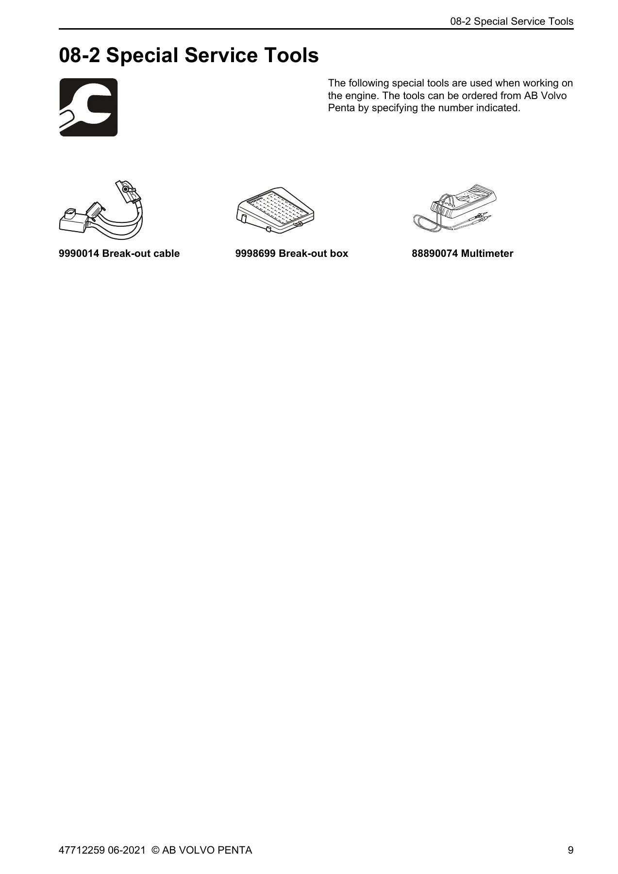
- 08-2 Special Service Tools – 9990014 Break-out cable, 9998699 Break-out box, 88890074 Multimeter
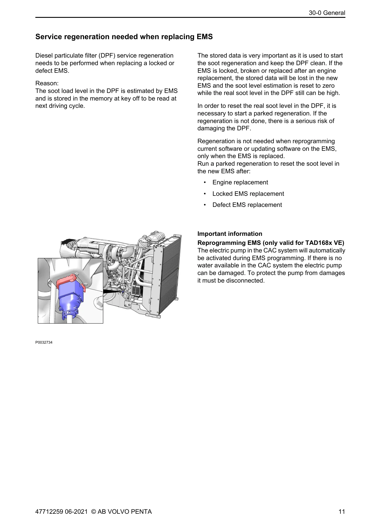
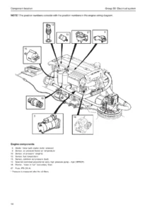
- 30-0 General – alternator principles, charging system checks, battery checks, service regeneration when replacing EMS, VODIA test routines
- 30-2 Fault Tracing – fault codes from P0016 through P2CE4 and U0001 through U3000
- 30-2 Measurements – EMS connector pin measurements, signal types, ignition-on and engine-running values
- 37-0 Wiring Diagrams – EMS 2.4 pin description for connector A and connector B
- Index
- References to Service Bulletins
In practical terms the manual walks a technician through the whole electrical system in a logical order. It opens with the charging circuit and how to verify it with a multimeter across the battery and alternator at 1500 rpm, then moves into the EMS-level material. The VODIA test routines chapter documents the relative compression test, the injector click test, the EATS urea adaptation reset, the EATS reset, the F2 pump shut-off test, and the exhaust flap smart actuator mode and position diagnostic tests, including how to interpret an OK, Not Reliable or Not Tested evaluation.
The measurement chapter is where the manual becomes genuinely usable at the bench. It lists each component against its EMS pin, its measure box number, its connector pin number, its signal type, and the values expected both at ignition-on and with the engine running. That includes air filter indicator, air inlet pressure and intake manifold temperature, camshaft, coolant level, coolant pump, coolant temperature, crankshaft, eEPG, EGR valve, ePRV, exhaust pressure, fan, fuel pressure, fuel pressure regulator, oil cooling jet pressure, oil level and temperature, oil pressure, oil thermostat valve, preheat relay and sense, rail pressure and temperature for both the TAD58X/TAD88X and TAD118X/TAD138X groups, throttle, wastegate valve and water in fuel. The manual then backs those measurements with eight resistance and voltage tables covering intake manifold temperature, coolant temperature, air filter temperature, oil temperature, rail temperature, oil/fuel/exhaust pressure, air inlet pressure and rail pressure across their operating ranges.
Fault Code Coverage
The fault tracing section is the largest part of the document and covers the powertrain and network code families in full. Each entry follows the same structure, so once you have read a few you can navigate any of them quickly: SPN and FMI, node, FTB name, lamp status, DTC monitor detection time, functional behaviour description, failure event, possible root cause and corrective action.
Fuel system codes are dealt with in depth, including rail pressure too low and too high, low pressure fuel system pressure deviations, fuel pressure regulator control short to ground, short to battery and open circuit, fuel system small leak detection, fuel pressure relief control faults, fuel rail pressure too low during cranking, and closed loop fuel pressure control at limit in both directions. Injector codes are listed cylinder by cylinder for cylinders 1 through 6, with separate short-to-ground, short-to-battery and open-circuit entries for each.
Sensor and actuator coverage includes crankshaft and camshaft position correlation and signal faults, ambient air temperature, manifold absolute pressure and barometric pressure, intake air temperature, engine coolant temperature, engine oil temperature, fuel temperature, engine oil pressure, engine coolant pressure, fuel rail pressure sensor, exhaust gas temperature sensors, exhaust pressure sensor, NOx sensors upstream and downstream, reductant level and quality sensors, water in fuel sensor, and air filter indicator. Actuator and control circuits include the supercharger boost control, EGR control, exhaust pressure control valve, throttle and diesel intake air flow control, intake air heater, fan control, starter relay, generator control, VCB control circuits, charge air cooler coolant pump, piston cooling oil control, oil thermostat and coolant pump.
Aftertreatment diagnostics are covered extensively, including DPF differential pressure critically high and moderately high, DPF restriction and soot accumulation thresholds, particulate filter pressure sensor plausibility, aftertreatment system over temperature, SCR NOx catalyst efficiency inducement, reductant dosing valve inducement, AdBlue consumption too low, and catalyst system over temperature with the parked sulphur regeneration request. Network codes round out the section with CAN backbone 1 and 2 bus off, engine subnet communication, lost communication with body control module, NOx sensors, charge air cooler coolant pump, exhaust pressure control valve and reductant control module, plus control module internal and checksum failures.
Wiring and Connector Reference
The wiring diagram section gives the EMS 2.4 pin description for both connector A and connector B, listing every populated pin with its function. That includes sensor supply and ground pins, pressure and temperature inputs, switch inputs, current drives, H-bridge outputs, peak hold PWM outputs, CAN channels and EECU supply and ground pins. This is what allows a technician to confirm a circuit at the connector rather than replacing parts on suspicion.
What This Manual Lets You Do
With this Volvo Penta Group 30 Electrical System workshop manual on hand you can carry out structured fault tracing on the TAD580-583VE, TAD880-884VE, TAD1180-1184VE, TAD1380-1384VE and TWD1683VE/GE engines rather than working from symptoms alone. You can pull a fault code, look up its SPN and FMI, read the failure event that triggered it, and follow the numbered corrective actions to the likely root cause. You can measure a sensor or actuator at the EMS pin with the values the manual expects, both statically and with the engine running, and compare against the resistance and voltage tables. You can verify the charging system, run the VODIA service routines the manual describes, and confirm the EMS pinout before touching a harness.
Getting the electrical system right matters because these engines rely on the EMS for fuelling, aftertreatment dosing, derate strategy and protection. A misdiagnosed sensor or a harness fault left in place can push the engine into a derate, block a DPF regeneration, or trigger an inducement that limits the machine. Working from the published fault code tree and the measured values instead of guesswork keeps the repair correct the first time and protects the components around it.
IMAGES PREVIEW
Delivery is instant. The manual is supplied as a PDF download after payment, with no shipping and no waiting. It opens on a laptop, tablet or phone in the workshop, and pages can be printed for the job at hand so the relevant fault code entry or pinout table is next to the machine while you work.
Reviews
There are no reviews yet.