
Volvo Penta IPS EVC-C Group 30 Electrical System Workshop Manual
Original price was: $39.95.$22.95Current price is: $22.95.
Complete Volvo Penta workshop manual for the Group 30 Electrical system on IPS 350/400/500/600 with EVC-C. Covers D4 and D6 marine diesel engines, EDC7, PCU, SHCU, SUS, fault codes, wiring diagrams and calibration.
Description
Volvo Penta IPS EVC-C Group 30 Electrical System Workshop Manual
This is the Volvo Penta workshop manual for the Group 30 Electrical system on the IPS (Inboard Performance System) with EVC-C electronic vessel control. It covers the D4-260D-B, D6-310D-B, D6-370D-B and D6-435D-A marine diesel engines fitted to the IPS 350, IPS 400, IPS 500 and IPS 600 drive packages. The document is the reference used for fault tracing, diagnostics, component description, calibration and repair of the complete electrical network — EDC7 engine control unit, PCU (Powertrain Control Unit), SHCU (Steering Helm Control Unit), SUS (Servo Unit Steering), sensors, actuators, wiring and CAN bus communication.
File Details
- Manual type: Workshop Manual — Group 30 Electrical system
- Brand / publisher: Volvo Penta
- Product series: IPS with EVC-C
- Covered models: IPS 350, IPS 400, IPS 500, IPS 600
- Covered engines: D4-260D-B, D6-310D-B, D6-370D-B, D6-435D-A
- Language: English
- Publication number: 7745565
- Publication date: 09-2007
- Copyright: © 2006 AB Volvo Penta
- Page count: 291 pages
- File format: PDF
Chapters Covered
- Safety information and important notes
- General information: About this Workshop Manual, Spare parts, Certified engines, Repair instructions, Our common responsibility, Tightening torques, Special tools
- Design and function: System description EDC7, EVC system
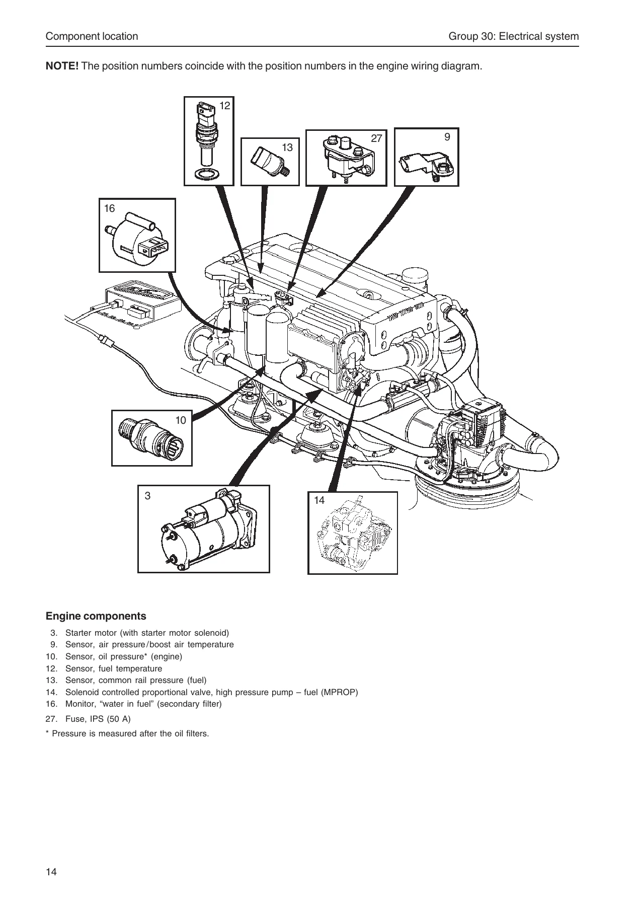
- Component location and component description
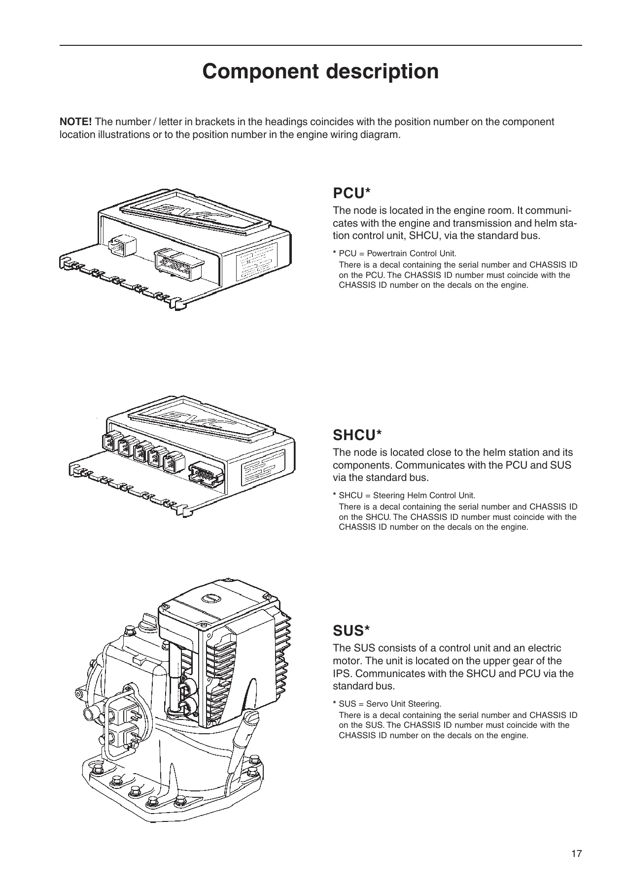
- PCU, SHCU and SUS — node description and identification
- Control: potentiometer and neutral switch
- Solenoid valves, transmission
- Resolver, Starter motor, Alternator, Injectors
- Sensors: engine speed (flywheel), camshaft position, boost air pressure and boost air temperature, lube oil pressure (engine), coolant temperature, fuel temperature, common rail pressure (fuel)
- Magnetically controlled proportional valve (MPROP)
- Supercharger, Water switch (secondary fuel filter)
- Engine control unit EDC7, Coolant level switch, Extra stop button
- Fuses and voltage converter DC/DC 12 V
- Repair instructions: general advice on working with EVC engines, electric welding, fault tracing of cables and connectors, fault tracing of the starter motor and windings, rail pressure measurements
- Changing, identifying and reprogramming the engine control unit; programming an empty control unit
- Malfunctions: fault code information, FMI table, SAE standard, general advice
- System introduction EVC: starting sequence, network, manual fault tracing in bus cables, fault tracing the EVC system, checking the instruments, alarm display, time delay on alarm indication, coolant level monitor
- Diagnostic Trouble Codes — MID 128 (engine control unit EDC7), MID 164 (SHCU), MID 187 (PCU), MID 250 (SUS)
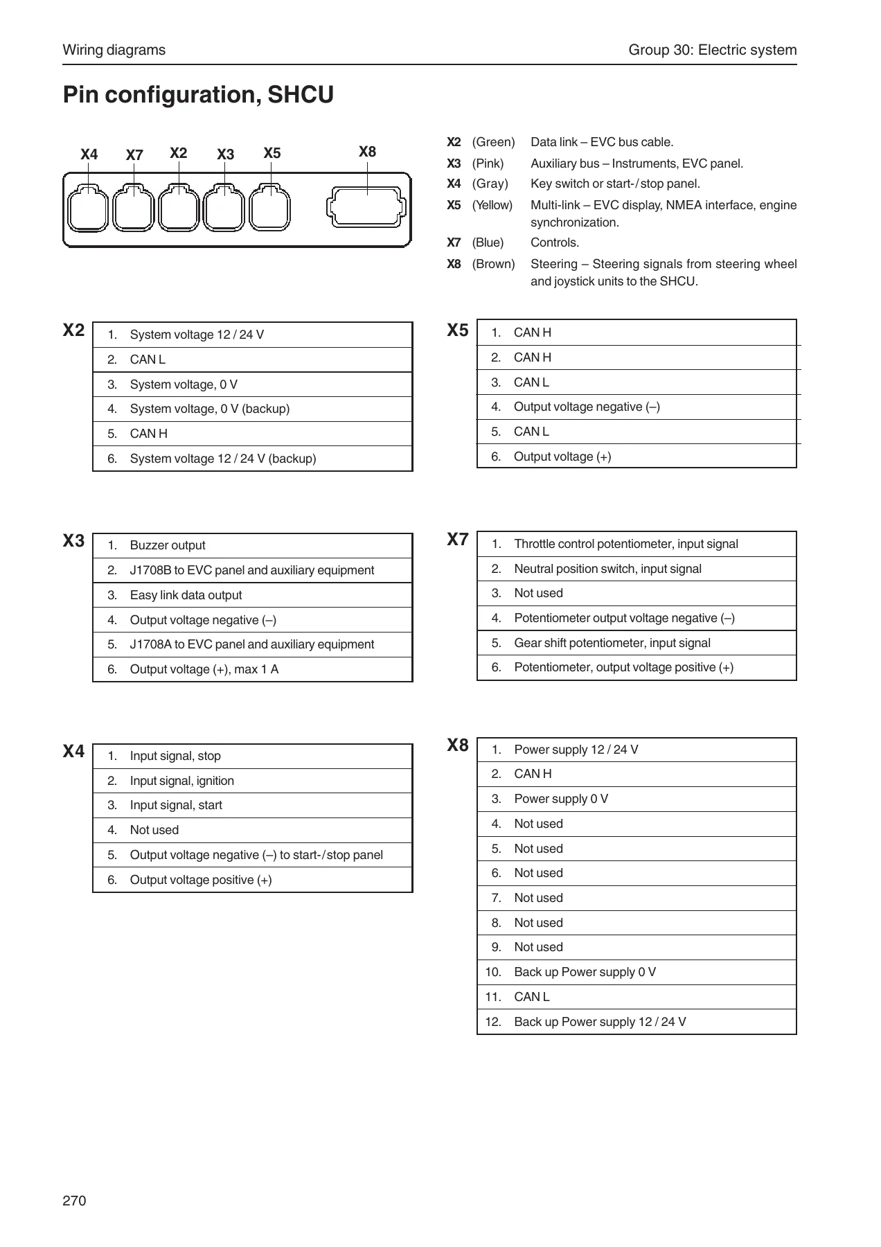
- Wiring diagrams: engine D4 / D6, controls, pin configuration PCU, pin configuration SHCU
- Calibration before start: calibration mode, auto configuration, combinations of control levers for EVC, lever calibration, idling speed calibration
- Checking the charging system
- Technical data
- References to Service Bulletins
- Index
What This Workshop Manual Covers
The Volvo Penta IPS EVC-C Group 30 Electrical System Workshop Manual goes far beyond a wiring schematic. It explains how the EVC-C distributed electrical network is structured across the three main nodes — PCU in the engine room, SHCU at the helm station and SUS on the drive leg — and how each node is programmed to a specific engine CHASSIS ID that must match the decals on the engine. Every external component connected to those nodes is described in detail: sensors, control levers, potentiometers, neutral switches, transmission solenoids, the resolver, the starter motor, the alternator, the injectors and the high-pressure fuel pump proportional valve (MPROP).
The diagnostic section is where the manual becomes genuinely usable in the workshop. It lists the fault codes by MID (message identification description) and PID / PPID / SID / PSID, so a code read from a VODIA tool can be tracked straight to a specific sensor, actuator or circuit. FMI tables translate the numeric failure modes into plain-English symptoms. Each fault code entry then walks through conditions for the code, possible reasons and the step-by-step suitable action — whether the fault is an open circuit, a short to battery voltage, a short to battery negative, abnormal updating rate or a mechanical non-response.
Repair instructions cover the practical side of working on an EVC-C system safely: the correct procedure for disconnecting the engine control unit connectors before electric welding, safe handling of the battery and main switches, correct measurement of rail pressure with the adapter cable and multimeter, and the resistance values that should be seen across the CAN bus and sensor circuits. The manual also explains the starting sequence, the difference between the CAN bus and the J1587 / J1708 diagnostic bus, and how to fault trace the bus cables manually.
Diagnostic and Fault Code Coverage
The Diagnostic Trouble Codes chapter is organised by control unit, which makes it fast to jump to the right section once a code has been read:
- MID 128 — Engine control unit (EDC7): throttle control position, water in fuel, oil pressure sensor, boost air temperature and pressure sensors, atmospheric pressure sensor, coolant temperature, battery voltage, fuel pressure, fuel temperature, engine speed / overspeed, injectors 1–6, camshaft position sensor, flywheel speed sensor, compressor coupling output, starter motor output, MPROP fuel pump output, ECM main relay, SAE J1939 data link, supply voltage, fuel pressure monitoring, redundant shut-off path, pressure relief valve monitoring, booster voltage high bank 1 and 2.
- MID 164 — SHCU: lever 1 and lever 2 position relative to potentiometer supply failure, lever potentiometer supply failure, data bus power input, key supply, main panel communication failure, steering wheel position, auto pilot fault, neutral switch and lever position mismatch, sync bus communication fault, program memory fault, SAE J1708 / J1587 data link, calibration memory failure, internal CPU faults, joystick faults, lever detection, calibrated lever travel too small, lever calibration procedure, lever(s) not calibrated, data bus network configuration fault, neutral button, lighting button, active station button, start, stop, steering wheel data link, steering wheel module, steering wheel brake, steering wheel controller, rudder angle, steering position divergence, incompatible sync bus version, data bus passive / active helm communication failure, SHCU communication failure with other helm, incompatible chassis ID and data bus communication warning.
- MID 187 — PCU: fuel level, transmission oil pressure sensor, transmission oil temperature sensor, data bus power input, transmission sensor supply, J1939 communication warning / fault, program memory fault, calibration memory failure, internal CPU faults, incompatible engine type, data bus network configuration fault, data bus power output, primary and secondary solenoid (high side switch), data bus communication with active helm failure, no data on engine bus, data bus communication with passive helm failure, incompatible chassis ID and data bus communication warning.
- MID 250 — SUS: battery input, ECU temperature, data bus power input, steering wheel position, rudder angle, servo motor temperature, program memory fault, calibration memory failure, internal CPU faults, data bus network configuration fault, data bus power output, servo motor, electro-mechanical rudder brake, data bus communication with active helm failure and data bus communication warning.
Who This Manual Is For
Volvo Penta workshops and marine service technicians working on IPS-equipped boats will recognise this as the source document for Group 30 electrical work. It is equally useful for boat owners, marine electricians and independent yards who need the actual fault-code logic, wiring pinouts and calibration procedures for an IPS 350, IPS 400, IPS 500 or IPS 600 installation with EVC-C. Because the manual is written around the D4 and D6 engine families, the electrical content applies across the entire IPS range covered in the table of contents.
Why It Matters
Getting electrical diagnostics wrong on an EVC-C system is expensive. A misread fault code can lead to a control unit being replaced when the real problem is a chafed CAN wire, a disconnected neutral switch or a corroded connector pin. This manual gives the actual measurement values, the correct pin numbers for every connector and the calibration sequence (auto configuration, lever calibration, idling speed setting) that the system expects after any component replacement. Without it, fault tracing the distributed network is guesswork.
IMAGES PREVIEW
The Volvo Penta IPS EVC-C Group 30 Electrical System Workshop Manual is delivered as an instant PDF download — no shipping, no waiting. It opens on any phone, tablet, laptop or desktop, and specific pages can be printed for use at the helm or in the engine bay. Whether you are chasing an intermittent CAN fault, replacing the SHCU, programming an empty engine control unit or simply checking charging system voltages, this manual puts the workshop procedure in front of you.
Reviews
There are no reviews yet.