
Volvo Penta Group 30 Electrical System Workshop Manual – TAD540 TAD550 TAD570 TAD840 TAD850 TAD870 D8 Marine
Original price was: $39.95.$23.95Current price is: $23.95.
Complete 338-page Volvo Penta Group 30 Electrical System workshop manual covering TAD540-2VE, TAD550-2VE, TAD570-2VE, TAD840-3VE, TAD850-3VE, TAD870-3VE and D8 marine engines. Includes full fault code diagnostics, electrical measurements, wiring diagrams, engine protection maps, and sensor specifications.
Description
File Details
- Manual type: Workshop Manual – Group 30 Electrical System
- Brand: Volvo Penta
- Models covered: TAD540-2VE, TAD550-2VE, TAD570-2VE, TAD840-3VE, TAD850-3VE, TAD870-3VE, D8 marine
- Additional model references: TAD570VE, TAD571VE, TAD572VE, TAD540-42VE, TAD550-52VE, TAD840-43VE, TAD850-53VE
- Language: English
- Page count: 338
- File format: PDF
- Document number: 47704990
- Edition: 12-2017
Chapters Covered
- General Information (00-0) – General, Specifications, Electrical Specifications, Engine Protection Map
- Safety and Other Instructions (05-1) – Safety Instructions
- Special Tools (08-2) – Special Service Tools
- General, Complete Vehicle Software (30-0) – General, Fault Tracing, Fault Codes, Measurements
- Cables and Fuses (37-0) – Wiring Diagrams
- Index and References to Service Bulletins
This Volvo Penta Group 30 Electrical System workshop manual is the dedicated electrical service reference for the TAD540-2VE, TAD550-2VE, TAD570-2VE, TAD840-3VE, TAD850-3VE, TAD870-3VE and D8 marine engine families. It brings together the electrical specifications, engine protection maps, fault code descriptions, measurement procedures, and wiring diagrams that a technician needs to diagnose and repair the engine management system (EMS), charging system, sensor circuits, and associated electrical components. Whether you are tracing an intermittent fault code, verifying sensor voltages at the EMS connector, or confirming the derate behaviour of a specific engine protection parameter, this manual provides the reference data and step-by-step direction.
Engine Protection Maps and Derating Behaviour
The manual opens with detailed engine protection maps that define how each engine model responds to abnormal operating conditions. Separate tables cover D8A1-A MP, TAD570VE/TAD571VE/TAD572VE, and the TAD540/TAD550/TAD840/TAD850 series, listing sensor signal ranges, warning thresholds, derating levels, and initial delay or fault detection times. For each monitored parameter – air inlet pressure, intake manifold temperature, coolant level, coolant temperature, engine speed (camshaft and crankshaft), exhaust gas temperature (wet and dry), oil level, oil temperature, and water in fuel – you get the exact warning and derate trigger points in both metric and imperial units.
Soft derate tables then show the remaining torque percentage at specific engine speeds and temperatures, so you can predict exactly how much power the engine will lose before a fault becomes critical. Separate maps for coolant temperature, oil temperature, intake manifold temperature, exhaust temperature (wet and dry), and EGR temperature give you the full derate curve. Oil pressure derating tables provide RPM-specific warning and alarm levels. This is the data you need to understand why an engine is derating, to verify that protection parameters are set correctly, and to diagnose whether a sensor reading is plausible or faulty.
Fault Codes and Diagnostic Troubleshooting
Hundreds of diagnostic trouble codes (DTCs) are documented in full detail. Each entry includes the SPN and FMI identifiers, DTC node, failure type, DTC description, monitoring condition, fault indication, detection time, replacement value, symptoms, DTC conditions, probable causes, and a numbered action list for fault tracing. The manual covers the full range of electrical and fuel system codes, including:
- Oil system codes – P019511, P019513, P029800, P052012, P052013, P052400, P108600, P109300, P112500, P250A11, P250A13, P250F00
- Coolant system codes – P011511, P011513, P021700, P048011, P048012, P048013, P052612, P111D00, P111E00, P255611, P255612, P255613, P256000
- CAN communication codes – U001088, U008088, U010A00, U010C00, U014100, U029D00, U029E00, U116F00, U117100
- Electrical codes – P05611F, P061511, P061512, P061513, P061519, P068573, P06B016, P06B017, P06B316, P06B317, P06E616, P06E617, P100111, P100112, P100113, P100190, P100192, U300001
- Fuel system codes – P008700, P008800, P008A00, P008B97, P009011 through P009B73, P00C600, P016800, P016E00, P016F00, P018501, P018511, P018513, P018564, P018F00, P019001 through P019062, and all six injector codes (P020111 through P020613)
- Intake air system codes – P004A11, P004A13, P004A7C, P004513, P004519, P004577, P004592, P006E17, P00D911, P00D913, P010512, P010513, P011011, P011013, P02E011 through P02E699, P054001, P054013, P054070, P05407F, P100211 through P100713, P10F800, P103011, P103012, P103013, P111600, P111800, P111900, P111A00, P112B00, P222613, P256214, P257831
- Exhaust system codes – P024311, P024312, P024313, P047001, P047012, P047013, P10C011, P10C012, P10C013, P102111, P102112, P102113, P112E00, P11A411, P11A412, P11A413, P11A500, P11A600, P119611, P119612, P119613, P119700, P119800, P242800
- EGR system codes – P04007C, P04009C, P040312, P040313, P040341, P040371, P040392, P040901, P040912, P040913, P040A01, P040A11, P040A13, P041A11, P041A12, P041A2A, P048613, P112100, P112200, P114E00, P245700
- EATS system codes – P054486, P114500, P203A86, P203F00, P204786, P204F93, P205A86, P206A64, P206A86, P207F9A, P208A86, P117A00
- NOx sensor codes – P220012, P220013, P220064, P220093, P22001C, P225D00, P225F00, P229E12, P229E13, P229E1C, P229E64, P229E93, P22FB92, P22FE00
- Programming codes – P060741, U300041, U300044, U300045, U300049
- DCU-related codes – MID 144 PSID 106, MID 187 PSID 216, MID 144 PID 28, MID 144 PID 29, MID 144 PID 91, MID 144 PID 158, MID 144 SID 231, MID 144 SID 240, MID 144 SID 253, MID 144 SID 254
A DTC interpretation guide explains the structure of the codes, including the meaning of the last two digits (00 for no sub type information, 01 for general electrical failure, 11 for circuit short to ground, 12 for circuit short to battery, 13 for circuit open, 16 for voltage below threshold, 17 for voltage above threshold, 64 for signal plausibility failure, 86 for signal invalid, and 88 for bus off). The code categories are grouped by system – oil, coolant, CAN communication, electrical, EATS, programming, fuel, EGR, intake air, exhaust, and NOx sensors – so you can quickly locate the relevant troubleshooting section.
Electrical Measurements and Sensor Testing
A comprehensive measurements section provides pin-level data for the EMS 2.3 control unit. Using the breakout cable 9990014, breakout box 9998699, and multimeter 88890074, you can measure voltage, resistance, and signal waveforms at every relevant connector pin. The manual specifies expected values for ignition-on and engine-running conditions, covering:
- Air inlet pressure / intake manifold temperature sensor (A11, A47, A7, A22)
- Camshaft position sensor (A46, A45)
- Coolant temperature sensor (B27, B6)
- Crankshaft position sensor (A38, A37)
- Air filter indicator (B31, B6, A29, A15)
- Oil level / temperature sensor (B3, B4, A31, A6)
- Oil pressure sensor (B17, B11, B18)
- EGR valve (B35, B36)
- Throttle actuator (B5, B17, B18, B24, B1)
- Fan control (A1, B49, A39, A35)
- Coolant level switch (B23, B10)
- Fuel pressure sensor (B17, B16, B18)
- Rail pressure / temperature sensor (A5, A19, A7, A11)
- Differential pressure EGR sensor (A21, A11, A7)
- Fuel pressure regulator MPROP (A16, A12)
- ePRV (A28, A62)
- Turbo speed sensor (A41, A42, A7)
- EGR temperature sensor (B48, B6)
- Exhaust pressure sensor (B12, B18, B17)
- VGT (B35, B36)
- Pre-NOx sensor (B35, B36)
- Preheat sense (B7) and preheat relay (B25, B10)
- Supercharger solenoid (B2)
- Wastegate valve (B38)
- Exhaust temperature sensors wet and dry (B43, B44, B18)
Conversion tables then translate voltage readings into temperature, pressure, and resistance values. Separate tables cover intake manifold temperature, coolant temperature, air filter temperature, oil temperature (including the D8 Pt-1000 sensor), rail temperature, EGR temperature, rail pressure, oil/fuel/exhaust pressure, air inlet pressure, and EGR differential pressure. This means you can verify a sensor’s output against the exact expected value at any operating temperature or pressure, without guesswork.
Wiring Diagrams and Connector Pin Data
The wiring diagrams section includes a complete pin description for the EMS 2.3 control unit, listing every pin from A01 through A62 and B01 through B62 with its function, signal type, and populated status. A separate DCU I/O interface connection table covers connectors A and B. The wiring diagram itself shows the DCU, backbone 1 and backbone 2 connections, battery positive and negative, switched battery, stop circuit, and the 6-pole VODIA connector and 8-pole connectors to the DCU and engine. A fuel system schematic illustrates the complete fuel circuit from tank through primary filter, feed pump, main filter, high-pressure pump, common rail, pressure relief valve, and return circuit, with pressure ranges for suction, feed, high pressure, and return lines.
A preheat function section explains the activation parameters (coolant temperature and oil temperature), the trigger values, and the relay control logic through EMS pins B25 and B7. The preheat activation time table shows how long the preheat function runs at various temperatures from 0 degrees C to -25 degrees C at sea level, across different engine models.
Who This Manual Is For
This Volvo Penta Group 30 Electrical System workshop manual is intended for qualified technicians, marine engineers, and industrial engine service personnel who already have a fundamental knowledge of the product and are able to carry out mechanical and electrical work to trade standard. It is not a beginner’s guide – it assumes familiarity with electrical measurement tools, oscilloscopes, and the VODIA diagnostic platform. The procedures reference special service tools 9990014, 9998699, and 88890074, and many diagnostic steps require the use of VODIA to log rail pressure, read fault codes, or perform actuator tests. Where VODIA is needed, the manual indicates it with a dedicated symbol.
The safety instructions section at the start of the manual covers essential precautions for working on running engines, hot surfaces, electrical systems, batteries, fuel systems, and lifting. It includes warnings about high-pressure fuel injection, battery electrolyte, rotating components, and the correct procedure for immobilising the engine before work begins. The manual also explains the DTC erase procedure, including the requirement to perform an Erase DTC operation in VODIA after repair and to allow the system to shut down properly – particularly important for the EATS system, which can take up to two minutes to shut down after an aftertreatment event.
Coverage Across Marine and Industrial Applications
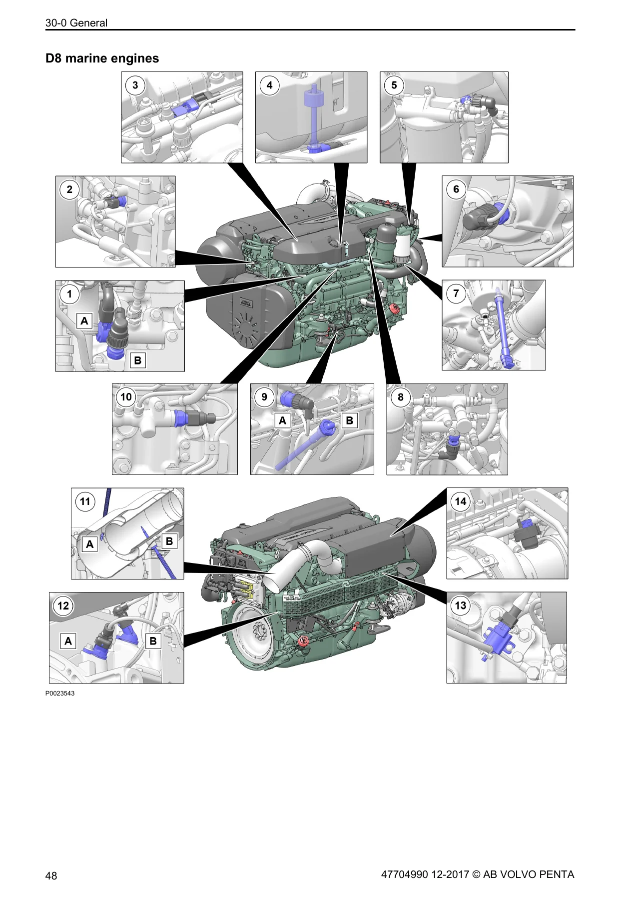
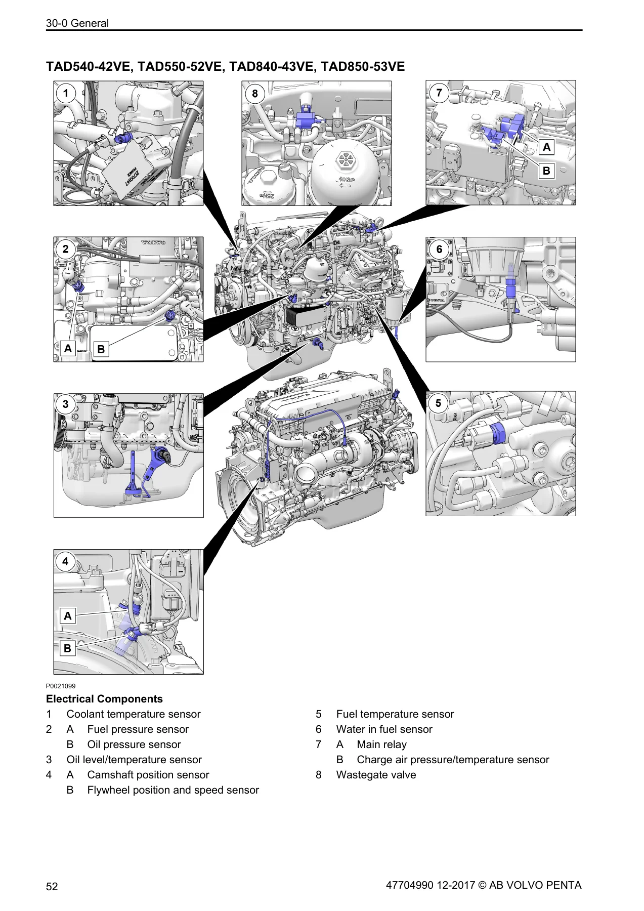
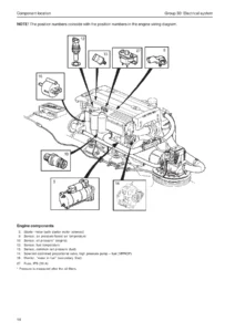
The manual covers both marine and industrial engine variants. For marine engines, the electrical component layout diagrams show sensor and actuator locations on the engine, including coolant temperature sensor, fuel pressure sensor, oil pressure sensor, oil level/temperature sensor, camshaft position sensor, flywheel position and speed sensor, NOx sensor, turbine speed sensor, exhaust manifold pressure sensor, water in fuel sensor, charge air pressure/temperature sensor, differential pressure sensor, EGR temperature sensor, and fuel pressure/temperature sensor. The engine control system description explains the EMS (Engine Management System) architecture, with the engine ECU mounted on vibration-damping rubber feet on the left side of the engine, receiving inputs from the accelerator pedal and engine sensors via DIN standard connectors.
For industrial engines, the EMS inputs and outputs are shown in a separate diagram, including exhaust manifold pressure, turbine speed, NOx sensor post-cat, EGR flow, and exhaust temperature EGR. Outputs include fuel quantity, engine diagnosis, injection timing, crank signal to starter motor, EGR, EATS, air throttle, VGT, cooling fan control, and air pre-heater cold start. This makes the manual suitable for both marine and industrial applications across the TAD540, TAD550, TAD570, TAD840, TAD850, TAD870, and D8 engine families.
Get the Complete Electrical Reference for Your Volvo Penta Engine
With this Volvo Penta Group 30 Electrical System workshop manual, you can diagnose and repair electrical faults on TAD540-2VE, TAD550-2VE, TAD570-2VE, TAD840-3VE, TAD850-3VE, TAD870-3VE, and D8 marine engines with confidence. The combination of engine protection maps, fault code descriptions, measurement data, wiring diagrams, and sensor specification tables gives you the complete picture – from understanding why a derate is active to tracing the exact circuit responsible for a fault code.
Correct procedures and accurate specifications matter because these engines rely on precise sensor signals and EMS-controlled actuators for fuel injection, emissions control, and engine protection. A misdiagnosed sensor or an incorrect rail pressure reading can lead to unnecessary parts replacement, extended downtime, or an engine that continues to derate. This manual helps you avoid that by providing the manufacturer’s own test values, fault code logic, and troubleshooting sequences.
IMAGES PREVIEW
Delivered as an instant PDF download after payment, this workshop manual can be viewed on any device – laptop, tablet, or smartphone – and printed if you prefer a paper copy in the workshop. There is no shipping, no waiting, and no subscription. You get the full 338-page document immediately, ready for use in the field or the workshop.
Reviews
There are no reviews yet.