
Volvo Penta TAD D4 D6 D8 Marine Engine Workshop Manual – Group 30 Electrical System PDF
Original price was: $34.95.$21.95Current price is: $21.95.
Volvo Penta Workshop Manual for Group 30 Electrical System covering TAD540, TAD550, TAD570, TAD840, TAD850, TAD870 and D4, D6, D8 marine engines. 344-page PDF with fault codes, measurements, wiring diagrams and CAN diagnostics.
Description
Volvo Penta TAD D4 D6 D8 Marine Engine Electrical System Workshop Manual – Group 30
This Volvo Penta Workshop Manual for Group 30, the Electrical System, covers the TAD540-2VE, TAD550-2VE, TAD570-2VE, TAD840-3VE/GE/B, TAD850-3VE and TAD870-3VE engines together with the D4, D6 and D8 marine engines. It is the document a technician reaches for when an electrical fault appears on one of these engines, when a fault code has to be read out and acted on, or when a sensor, actuator, relay or wiring circuit needs to be tested against the values the engine management system (EMS 2.3) expects. The Volvo Penta Group 30 Electrical System workshop manual moves from general safety and workshop information straight into fault tracing by system, then supplies the measurement data and wiring information needed to confirm what the fault code is pointing at.
File Details
- Manual type: Workshop Manual – Group 30 Electrical System
- Brand: Volvo Penta
- Covered engines: TAD540-2VE, TAD550-2VE, TAD570-2VE, TAD840-3VE/GE/B, TAD850-3VE, TAD870-3VE, D4, D6, D8 marine
- Language: English
- File format: PDF
- Publication number: 47704990
- Edition: 11-2023
- Page count: 344 pages
Chapters Covered
- 00-0 General – general information, replacement parts, certified engines, colors used in images, safety information
- 03-3 Specifications, Electrical – Engine Protection Map reference
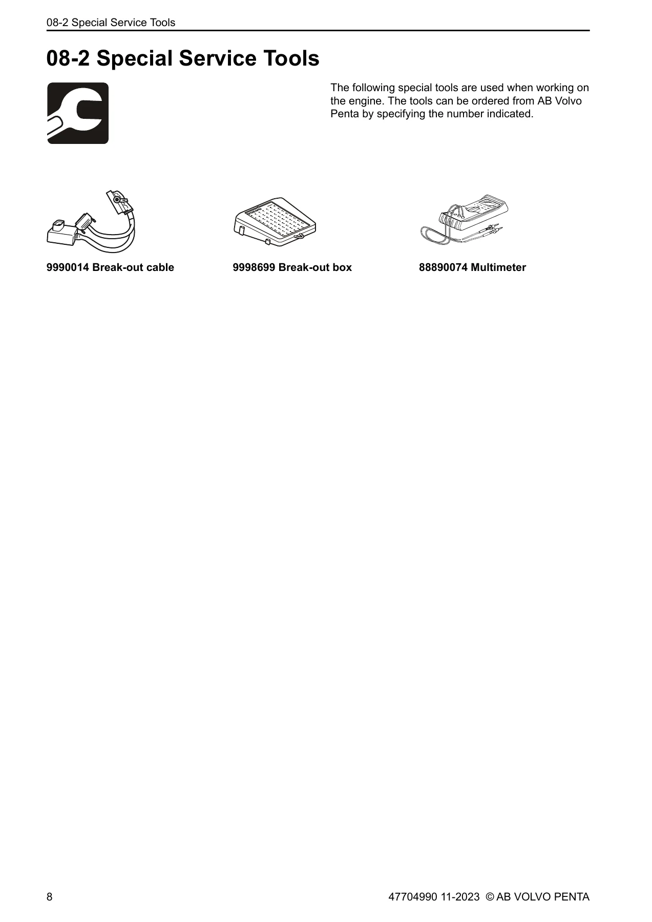
- 08-2 Special Service Tools – breakout cable 9990014, breakout box 9998699, multimeter 88890074
- 30-0 General – alternator function, charging system checks, DTC interpretation, DTC categories by system
- 30-2 Fault Tracing – the core of the manual: fault codes by system (Fuel System, Oil system, Coolant System, CAN communication, Electrical, EATS, Programming, EGR system, Intake air system, Exhaust System, NOx Sensors), plus measurements
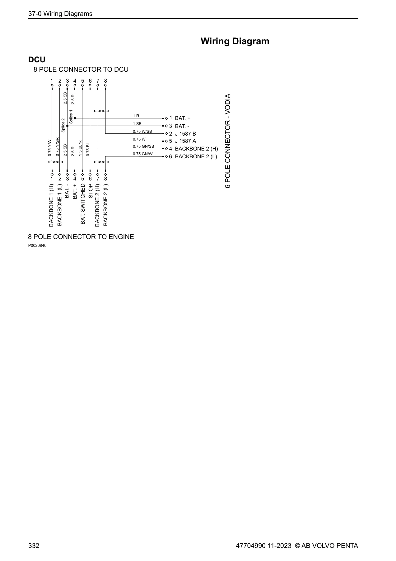
- 37-0 Wiring Diagrams – pin description for EMS 2.3, SPN list, DCU wiring diagram, preheat function
- Index – alphabetical fault code reference
- References to Service Bulletins
Read as a whole, the Volvo Penta TAD D4 D6 D8 Group 30 Electrical System workshop manual gives a technician the complete electrical troubleshooting path for these engines: identify the fault code through VODIA, look up the code in the fault tracing chapter, follow the probable cause and action steps, confirm the result with the measurement values in the measurements chapter, and check the wiring against the 37-0 diagrams. Each fault code entry follows a consistent structure – system, SPN/FMI, DTC node, failure type, DTC description, monitoring condition, fault indication, DTC stored, replacement value, symptom, DTC conditions, probable cause and action – so the technician is never guessing what to check next.
Fault Codes and Systems You Can Diagnose
The fault tracing chapter is organised by system, making the Volvo Penta Group 30 electrical manual practical when the fault code is already known. Each system contains the codes that belong to it, with the SPN/FMI numbers printed alongside the manufacturer DTC code.
- Fuel System – rail pressure too low/too high, low-pressure fuel system pressure, fuel pressure regulator control, fuel system leak detection, fuel pressure relief control (ePRV), rail pressure during cranking, injectors on cylinders 1-6, fuel quantity regulator (SCV), fuel temperature sensors and water-in-fuel
- Oil system – oil temperature sensor, oil pressure sensor/switch, oil pressure too low, oil level sensor, oil level too low, oil over temperature
- Coolant System – coolant temperature sensor, coolant over temperature, fan control circuit, fan speed sensor, coolant level sensor/switch, coolant pressure sensor, seawater pressure sensor
- Intake air system – manifold absolute pressure/barometric pressure, intake air temperature, ambient air temperature, VGT and supercharger boost control, diesel intake air flow control (throttle), intake air heater, preheat relay, air filter indicator and clogged air filter, charge air cooler coolant pump, turbocharger speed sensor
- Exhaust System – wastegate solenoid, exhaust pressure sensor, exhaust pressure control valve (EPG), Volvo Compression Brake (VCB) control circuits, exhaust gas temperature sensors (wet and dry)
- EGR system – EGR flow, EGR control, EGR sensors, EGR temperature sensors, EGR cooler efficiency
- EATS – SCR NOx catalyst efficiency, reductant level, reductant injection valve, SCR dosing performance, reductant tank temperature, reductant quality, reductant pump
- NOx Sensors – pre-NOx and post-NOx sensor circuits, heater control, sensing element performance, signal stuck low
- CAN communication – backbone 1 net, engine subnet, lost communication with EGR module, VGT module, VMCU, NOx sensors, charge air cooler coolant pump, EPG, reductant control module and body control module
- Electrical – system voltage unstable, EMS voltage supply, starter relay, main relay, sensor power supplies, engine stop switch, preheat relay, air filter indicator, compression brake control circuits
- Programming – ECU checksum, data memory, program memory and internal electronic failures
Measurements and Wiring Data
The measurements chapter shows how to connect breakout cable 9990014 and breakout box 9998699 to the EMS 2.3 connectors (A is black, B is grey) so every pin is accessible for testing. Component-by-component tables list the EMS pin, measure box position, connector pin, signal type and the expected reading at ignition on and engine running. This covers air inlet pressure and intake manifold temperature, camshaft and crankshaft position sensors, coolant temperature, oil level and temperature, oil pressure, fuel pressure, rail pressure and temperature, EGR valve, throttle, fan, coolant level, fuel quantity regulator, ePRV, turbo speed, exhaust pressure, VGT, preheat, supercharger solenoid, wastegate valve, exhaust temperature (wet and dry), fuel leakage pressure, coolant pressure, seawater pressure, fuel temperature and water-in-fuel. Sensor resistance and voltage tables for intake manifold temperature, coolant temperature, air filter temperature, oil temperature (including the D8 Pt-1000 sensor), rail temperature, EGR temperature, rail pressure, oil/fuel/exhaust pressure, air inlet pressure, EGR differential pressure, coolant/seawater pressure and fuel pressure complete the measurement data.
The 37-0 Wiring Diagrams chapter adds a full pin description for the EMS 2.3 connector (A01-A62 and B01-B62), a complete SPN list pairing every ISO DTC code to its J1939 SPN and FMI values, and the DCU and engine 8-pole connector wiring diagram. There is also a short preheat function description that explains the activation parameters, the B25 preheat relay control and the B7 heating element sense circuit.
Why This Manual Matters for TAD and D4/D6/D8 Owners and Technicians
Electrical faults on these engines do not usually announce themselves clearly. A hard-starting D4, a D6 that derates under load, a D8 marine engine that stops unexpectedly, or a yellow alarm on the EVC panel can come from a sensor reading slightly outside range, a chafed wire in the engine subnet, a stuck ePRV, a clogged EGR cooler, a dosing valve that has stopped working, or a preheat relay that is not closing in cold weather. Without the fault code structure, the SPN/FMI numbers and the expected measurement values, tracing the fault becomes guesswork and parts are replaced that were never at fault.
This Volvo Penta Group 30 Electrical System workshop manual gives the technician the fault code interpretation (P = Powertrain, U = Network), the most common failure types (00 no sub type information, 01 general electrical failure, 11 short to ground, 12 short to battery, 13 circuit open, 16 voltage below threshold, 17 voltage above threshold, 64 signal plausibility failure, 86 signal invalid, 88 bus off), the full DTC category list by system, and the action steps for every code in the manual. It also gives the reference values needed to confirm the diagnosis before a component is changed, which is the difference between a repair that lasts and a repair that comes back.
IMAGES PREVIEW
Instant PDF Delivery
The Volvo Penta TAD540 TAD550 TAD570 TAD840 TAD850 TAD870 D4 D6 D8 Group 30 Electrical System workshop manual is delivered as a downloadable PDF immediately after payment. There is no shipping and no waiting. The file can be opened on a laptop, tablet or phone, searched for a fault code or a pin number, and printed for use in the workshop. Whether you are working on a TAD840-3VE, a TAD870-3VE, a D4, a D6 or a D8 marine engine, the same document covers the electrical system, the fault tracing, the measurements and the wiring.
Reviews
There are no reviews yet.