
Volvo Penta TAD580-583VE TAD880-884VE TAD1180-1184VE TAD1380-1384VE TWD1683VE/GE Group 30 Electrical System Workshop Manual 2022 – Fault Codes, Wiring Diagrams & Measurements
Original price was: $44.95.$27.95Current price is: $27.95.
Volvo Penta workshop manual for Group 30 Electrical System, April 2022 edition, covering TAD580-583VE, TAD880-884VE, TAD1180-1184VE, TAD1380-1384VE and TWD1683VE/GE engines. Full fault code fault tracing, VODIA test routines, EMS 2.4 pin data, sensor measurement tables and wiring diagram pin descriptions.
Description
Volvo Penta Group 30 Electrical System Workshop Manual – Fault Tracing for TAD580-583VE, TAD880-884VE, TAD1180-1184VE, TAD1380-1384VE and TWD1683VE/GE
This is the Volvo Penta workshop manual for the electrical system of the TAD580-583VE, TAD880-884VE, TAD1180-1184VE, TAD1380-1384VE and TWD1683VE/GE engine families, published in the 04-2022 edition. Rather than a general service book, it is built around one job: taking a stored diagnostic trouble code on an EMS-controlled Volvo Penta industrial engine and following it, step by step, to a repaired machine. Every P-code and U-code entry is laid out with the SPN/FMI pair, the FTB name, lamp status, monitor detection time, functional behaviour description, failure event, possible root cause and the numbered corrective actions the technician is expected to work through. Around that core sit the support sections that make the codes usable in practice – charging system checks, VODIA test routines, EMS pin data, sensor resistance and voltage tables, and the EMS 2.4 connector pin description.
File Details
- Manual type: Workshop Manual, Group 30 Electrical System
- Brand: Volvo Penta
- Engines covered: TAD580-583VE, TAD880-884VE, TAD1180-1184VE, TAD1380-1384VE, TWD1683VE/GE
- Language: English
- Document number: 47712292
- Edition / date: 04-2022
- Page count: 350
- File format: PDF
Chapters Covered
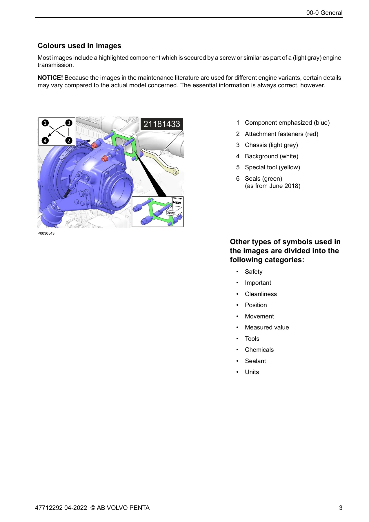
- 00-0 General – General Information, Replacement Parts, About this Workshop Manual, Certified Engines, Colours Used in Images, Safety Information, safety precautions for immobilising the engine, hot surfaces, fuel systems, batteries and high-pressure washing
- 03-3 Specifications, Electrical – Specifications, Electrical, and the Engine Protection Map reference
- 08-2 Special Service Tools – Break-out cable 9990014, Break-out box 9998699, Multimeter 88890074
- 30-0 General – Generally about alternators, Measurements, Checking the charging system, Fault tracing charging system (no charge, undercharge, overcharge), Service regeneration needed when replacing EMS, VODIA test routines, DTC interpretation
- 30-2 Fault Tracing – Fault Codes, each entry giving SPN [FMI], node, FTB name, lamp status, DTC monitor detection time, DTC monitor test conditions, functional behaviour description, failure event, possible root cause and corrective action
- Measurements – Component-by-component EMS pin and signal value tables for ignition on and engine running conditions
- Sensor reference tables 1-8 – Intake manifold temperature, coolant temperature, air filter temperature, oil temperature, rail temperature, oil/fuel/exhaust pressure, air inlet pressure and rail pressure
- 37-0 Wiring Diagrams – EMS 2.4 pin description for the A connector (A01-A62) and B connector (B01-B62) with populated pin identification
- Index – Alphabetical index of fault codes from P001676 through U300049, plus references to Service Bulletins
Read together, these chapters turn the manual into a complete electrical diagnostic workflow: identify the code, understand what the EMS saw, verify the circuit with the right pin and the right meter reading, then act. The fault code section alone spans the entire fuel system, air and exhaust management, aftertreatment and communications architecture of these engines, and each entry is written so a technician can move from the code description straight into a measurable check.
Fault Code Coverage in Depth
The fault tracing chapter is organised as a long sequence of individual code entries. Commonly encountered families include:
- Fuel system – rail pressure too low or too high, low pressure fuel system pressure faults, fuel pressure regulator control, ePRV fuel pressure relief control, fuel system leak detection, fuel temperature faults, water in fuel
- Injectors and fuel metering – cylinder 1 to 6 injector circuit faults, injection pump fuel metering control, closed loop fuel pressure control at limit
- Air management – manifold absolute pressure and barometric pressure correlation, intake air temperature, diesel intake air flow control and position sensor, turbocharger underboost and overboost, wastegate solenoid, supercharger boost control
- Exhaust and aftertreatment – EGR flow and control, exhaust pressure sensor and control valve, EPG actuator tests, DPF differential pressure and soot accumulation, exhaust gas temperature sensors, SCR NOx conversion, reductant level and quality, NOx sensors upstream and downstream
- Sensors and switches – crankshaft and camshaft position, engine coolant temperature and level, oil pressure, oil temperature, oil level, piston cooling oil pressure, ambient air temperature, air filter indicator
- Electrical and control – sensor power supply A, B and C, system voltage unstable, starter relay, preheat and intake air heater control, fan control and fan speed, VCB control, engine stop switch, EMS control module internal faults
- Network – CAN backbone 1 and 2 bus off, engine subnet, lost communication with DCU, with NOx sensors, with the charge air cooler coolant pump, with the exhaust pressure control valve and with the reductant control module
How Each Fault Code Entry Is Structured
Every code is presented the same way, which is what makes the manual usable under pressure. The header identifies the fault with its SPN and FMI numbers and the FTB name, so the entry can be matched against a code read from the EMS or from VODIA. Below that, the lamp status tells the operator how serious the fault is treated as being. The monitor detection time and test conditions state what the EMS needed to see, and for how long, before storing the code. The functional behaviour description then explains the real-world consequence – a derate, a shutdown, a hard start, a supercharger that stays engaged, a fan that never shuts off. The failure event gives the electrical or mechanical threshold that triggered the entry, and the possible root cause and corrective action sections give the checks to perform, often naming the exact connector pin involved.
For circuit faults this pin-level detail is unusually specific. Entries name the pin and the expected condition – for example a short to ground or a short to battery on a particular EMS pin, or a voltage outside a stated range. This lets a technician go directly to the connector with the break-out box and multimeter rather than working through the harness by elimination.
Measurements, Sensor Tables and Wiring Data
The measurements chapter lists components against EMS pin numbers, measure box positions, signal type and expected values both at ignition on and with the engine running. Air filter indicator, air inlet pressure and intake manifold temperature, camshaft, coolant level, coolant pump, coolant temperature, crankshaft, eEPG, EGR valve, ePRV, exhaust pressure, fan and fan speed sensor, fuel pressure, fuel pressure regulator, oil cooling jet pressure, oil level and temperature, oil pressure, oil thermostat valve, preheat relay and preheat sense, rail pressure and temperature, throttle, wastegate valve and water in fuel are all tabulated.
Eight supporting reference tables convert resistance and voltage readings into real temperatures and pressures – intake manifold temperature, coolant temperature, air filter temperature, oil temperature, rail temperature, oil/fuel/exhaust pressure, air inlet pressure and rail pressure. These tables matter because the manuals for these engines rely on sensor voltage interpretation rather than simple go/no-go testing, and the tables are what let a technician tell a genuine sensor failure from a wiring problem.
The wiring diagram section closes the loop with a full EMS 2.4 pin description for both connectors, identifying which pins are populated and what each carries – supply voltages, grounds, pressure inputs, temperature inputs, switch inputs, PWM outputs, CAN lines, crank and cam speed signals and injector drive outputs.
VODIA Test Routines and Regeneration Procedures
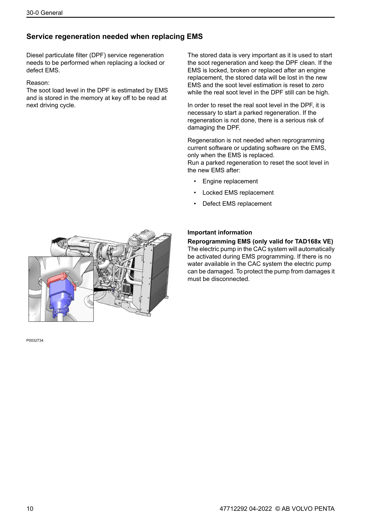
The general chapter documents the guided routines that accompany the fault codes, including the relative compression test, the injector click test, the urea adaptation reset, the F2 pump shut off test, the exhaust flap smart actuator mode and position diagnostic tests, exhaust aftertreatment system cleaning, the DPF reset, and the SCR NOx conversion test. Just as importantly, it explains when a routine must be run – for example that a parked regeneration is required after an EMS replacement, an engine replacement or a locked EMS replacement, because the stored soot load level is lost with the old control unit and the new EMS assumes a clean filter. The manual also warns that during EMS programming on TAD168x VE the charge air cooler electric pump is activated automatically and must be disconnected if there is no water in the CAC system.
Who This Volvo Penta Electrical Fault Code Manual Is For
This manual suits workshop technicians, field service engineers, fleet maintenance staff and technically confident operators working on TAD580-583VE, TAD880-884VE, TAD1180-1184VE, TAD1380-1384VE and TWD1683VE/GE engines. It is written for someone who has diagnostic access to the engine – the corrective actions assume meter readings, oscilloscope checks on signal circuits, break-out box connections and, in many cases, VODIA routines. It is also a sound reference for anyone who simply wants to understand what a particular stored code means before authorising repair work, since each entry states the operational consequence of the fault as well as the fix.
Because the content is fault-code driven rather than a general overhaul guide, it should be understood as a diagnostic companion for the electrical system of these engines rather than a complete mechanical rebuild manual.
Get the Fault Codes, Pin Data and Wiring Information You Need
With this Volvo Penta Group 30 Electrical System workshop manual you can read a stored fault code and know what the EMS was monitoring, which circuit is implicated, which pin to probe, what voltage or resistance to expect, and which corrective action to take first. That turns a code into a repair plan instead of a guess, and it is the difference between replacing parts until the lamp goes out and fixing the fault that set it. The measurement tables and the EMS 2.4 pin description make it possible to verify a circuit properly, while the VODIA routine section tells you when a reset or regeneration is mandatory rather than optional – the kind of detail that prevents a new EMS or a new DPF from being damaged by a procedure done in the wrong order.
IMAGES PREVIEW
Delivered as an instant PDF download after payment, with no shipping and no waiting. Open it on a laptop, tablet or phone in the workshop, search the codes you need, print the pages you want for the bench, and keep it on file for the next time the same engine comes back with the same lamp.
Reviews
There are no reviews yet.