
Volvo Penta D9 D11 D12 D13 D16 EMS 2 Electrical System Workshop Manual – Group 30 Marine Engines
Original price was: $29.95.$17.95Current price is: $17.95.
Complete Group 30 Electrical System workshop manual for Volvo Penta D9, D11, D12, D13 and D16 marine engines with EMS 2 electronic management. Covers sensors, senders, fault codes, wiring, component locations, measurements, and shutdown system configuration.
Description
Volvo Penta D9 D11 D12 D13 D16 EMS 2 Electrical System Workshop Manual
This Volvo Penta workshop manual covers the Group 30 Electrical System for D9, D11, D12, D13, and D16 marine engines equipped with the EMS 2 electronic management system. Published under document number 47700583 and dated 09-2023, it provides the same technical depth used by professional marine technicians for diagnosis, repair, and maintenance of the complete engine electrical system. From sensor specifications and component locations to fault code tracing and shutdown unit configuration, this manual gives you the information needed to work confidently on these marine diesel engines.
File Details
- Manual Type: Workshop Manual (Electrical System – Group 30)
- Brand: Volvo Penta
- Models Covered: D9, D11, D12, D13, D16
- System: EMS 2 (Electronic Management System)
- Publication Number: 47700583
- Date: 09-2023
- Language: English
- Page Count: 194
- File Format: PDF
Chapters Covered
- 00-0 General
- General Information, Replacement Parts, Certified Engines
- Safety Information
- Colours Used in Images
- 03-3 Specifications, Electrical
- Switches and Senders
- Engine Protection Map
- 08-2 Special Service Tools
- 30-0 General
- Design and Function
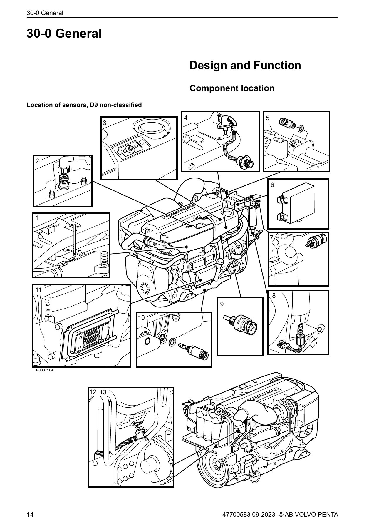
- Component Location (D9 non-classified, D13, D16 variants)
- Component Description
- System Description EMS 2
- Repair Instructions
- 30-2 Fault Tracing
- Fault Codes (MID 128, MID 158)
- Measurements
- 39-0 General
- Adjustment Parameters for Low-Speed or Trolling Function
- Checking Propeller Rotation
This workshop manual is dedicated entirely to the electrical system of the Volvo Penta D9, D11, D12, D13, and D16 marine engines running the EMS 2 management platform. It is not a general engine overhaul guide; it is a focused electrical diagnostic and repair resource that gives you the exact procedures, values, and component data needed to service the engine management system, sensor network, starting and charging circuits, and safety shutdown functions. The manual opens with general information and safety, moves into detailed electrical specifications for every switch and sender on these engines, then spends the bulk of its pages on design and function, component location, fault tracing, and measurement procedures.
Systems and Components Covered
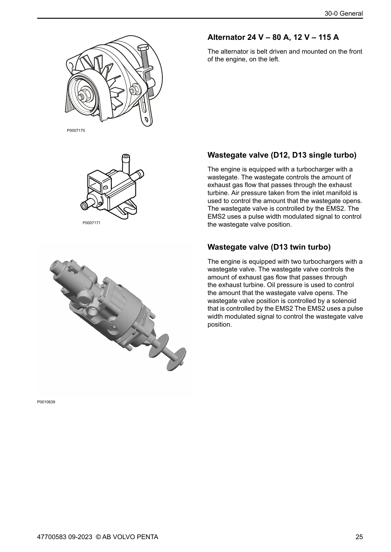
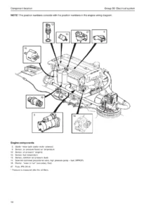
The component description chapter covers the AUX stop button in both non-classified and classified systems, the starter motor and its overheating protection, the alternator (24 V-80 A and 12 V-115 A), the wastegate valve for D12 and D13 single and twin turbo configurations, unit injectors, piston cooling switches and sensors, fuel pressure sensor, coolant temperature sensor, air inlet pressure and intake manifold temperature sensor, oil pressure and oil temperature sensors, camshaft and flywheel position sensors, external stop relay, engine control unit (EMS2), crankcase pressure sensor, oil level switch and sensor, coolant level switch, water in fuel switch, Power Module, DC/DC converter (D9), and the Shutdown Unit (SDU). Each component entry explains its function, location, electrical characteristics, and relationship to the EMS 2 control system. The manual also includes complete SDU configuration procedures for run detection, overspeed, and exhaust temperature channels.
Fault Tracing and Diagnostics
The fault tracing chapter is organised by MID/PID/SID/PPID fault code groups. Each fault code entry provides the fault code explanation, fault indication, symptoms, preconditions, conditions for setting the code, possible reasons, and suitable actions. Covered codes include coolant pressure, fuel delivery pressure, water in fuel, engine oil level and pressure, intake manifold temperature, air inlet pressure, air filter pressure drop, coolant temperature and level, crankcase pressure, ECU battery potential, transmission range, exhaust gas temperature, engine oil temperature, engine speed, starter output, key off input, piston cooling oil pressure, engine sync acknowledge, engine protection status, throttle calibrated position, seawater pressure, injector faults, engine position sensors, wastegate output driver, air compressor actuator, 5 V supply, program memory, controller, SAE J1939 data link, exhaust manifold water temperature, data link MID187, and power module battery and fuse circuits. The measurements chapter then gives step-by-step checking procedures for every sensor, switch, and actuator, with nominal values, measurement points, and tool references.
Specifications and Measurements
The electrical specifications chapter lists voltage, connector type, working range, pressure signal, temperature range, type, and tightening torque for each switch and sender. Examples include the water in fuel switch (12/24 V, 3-pin or 2-pin, closes when water detected), fuel pressure sensor (5 V, 0-700 kPa, 0.5-4.5 V signal), camshaft and flywheel sensors (2-pin inductive, -40 to +130 degrees C, 8 plus or minus 2 Nm), combined oil pressure and temperature sensors, coolant temperature sensor (NTC, -40 to +150 degrees C, 28 Nm), crankcase pressure sensor, seawater pressure sensor, coolant pressure sensor, piston cooling pressure sensor, wastegate valve (20-32 V, 90 plus or minus 4.5 ohms at 20 degrees C), alternator, and starter motor capacities for each engine variant. The measurement procedures provide nominal resistance and voltage values for supply cables, negative cables, signal cables, and the sensors themselves, along with injector coil resistance checks and injector trim procedures.
Who This Manual Is For
This Volvo Penta EMS 2 electrical system workshop manual is intended for marine technicians, service engineers, and experienced boat owners who need to diagnose and repair the electrical and electronic systems on D9, D11, D12, D13, and D16 marine engines. It assumes familiarity with basic electrical measurement tools such as a multimeter and, for some procedures, the VODIA diagnostic tool and specified break-out cables. The fault tracing sections reference special tools including the 885675 break-out cable, 9990014 break-out cable, 9998482 measuring tool, 9998534 break-out cable, 9998699 break-out box, 88890016 break-out cable, 88890074 multimeter, and 88820047 VODIA diagnostic tool.
Get Instant Access to the Complete Group 30 Electrical System Manual
With this manual, you can diagnose and repair the complete electrical system on Volvo Penta D9, D11, D12, D13, and D16 marine engines running EMS 2. Whether you are tracing an intermittent fault code, replacing a sensor, configuring the shutdown unit, or checking injector coils, the manual provides the exact procedures, nominal values, and component data you need. Correct electrical diagnosis on marine engines is critical: a misdiagnosed sensor or incorrect measurement can lead to unnecessary parts replacement, continued engine derating, or unsafe operating conditions. This PDF is delivered instantly after payment, requires no shipping, and can be viewed on any device or printed for workshop use.
IMAGES PREVIEW
Reviews
There are no reviews yet.