Description
Yamaha F70A Outboard Service Manual – F70AET Repair & Workshop PDF
This is the full Yamaha service manual for the F70A four-stroke outboard, issued under document number 6CJ-28197-3N-11 as the 1st Edition in May 2010. It is the workshop reference used for maintenance, disassembly, repair and reassembly of the F70AET and the F70A tiller handle variant, covering both the L-transom and X-transom lower unit configurations. Everything is here in one PDF – specification data, exploded component illustrations, tightening torques, wiring schematics, fault code tables and step-by-step service procedures for every major assembly on the motor.
File Details
- Manual type: Service Manual (workshop / repair)
- Brand: Yamaha
- Model: F70A / F70AET (plus F70A tiller handle model)
- Document number: 6CJ-28197-3N-11
- Edition: 1st Edition, May 2010
- Language: English
- Page count: 412 pages
- File format: PDF
Chapters Covered
The service manual is organised into numbered chapters with a full index and appendix at the back:
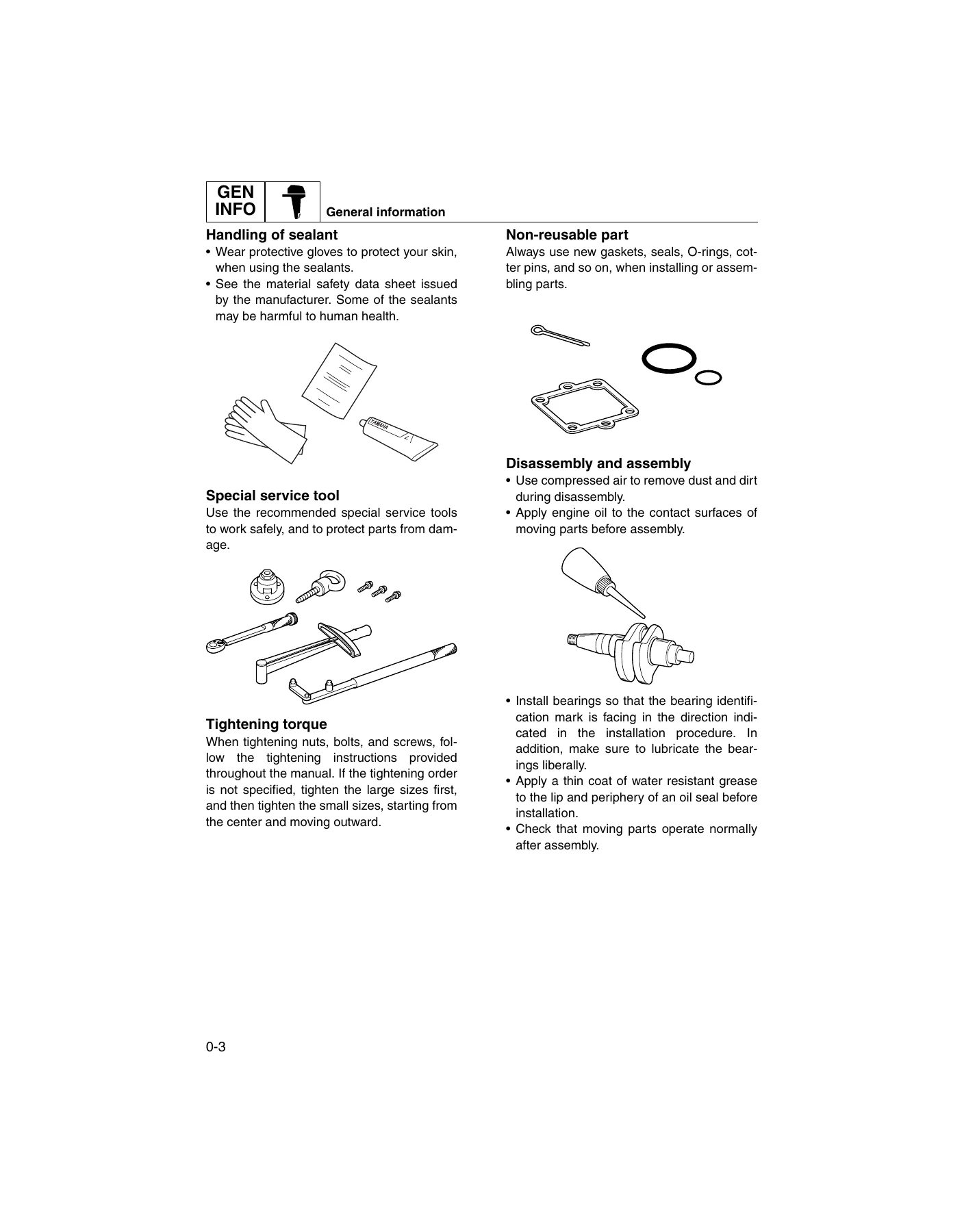
- General information – safety while working, rotating parts, hot parts, electric shock, propeller handling, gasoline handling, ventilation, self-protection, working with a crane, gas torch handling, sealants and lubricants, special service tools, tightening torque, non-reusable parts, disassembly and assembly practice, how to use this manual, abbreviations, symbol keys
- Specification – model data, dimensions and weight, performance, power unit, lower unit, bracket unit, fuel and oil requirements, battery and PTT fluid requirements, electrical system technical data, ignition timing control, fuel injection control, engine speed control, PTT system, charging and starting systems, gauges and sensors, fuel system data, power unit data, cylinder head and crankcase assembly data, lower unit data, bracket unit data, specified tightening torques, general tightening torque
- Technical features and description – electronic control system, ECM component layout, electronic fuel injection control, ignition timing control, engine speed control, knock control, ISC control, alert indicator and buzzer control, fail-safe control, Y-COP, power unit, fuel system diagram, lubrication diagram, cooling diagram, intake and exhaust diagram, PTT unit operation including trim-up, tilt-up, trim-down, tilt-down, stationary condition and shock-absorbing function
- Rigging information – outboard motor installation, dimensions, exterior views, clamp bracket, crate top cover pictographs, uncrating procedure, outboard motor mounting, rigging grommet mounting and description, installing shift and throttle cables, installing the wiring harness, installing the 6Y8 Multifunction Meter harness, installing the remote control box and tachometer, optional equipment including water pressure sensor, speed sensor and tiller handle, installing Y-COP, registering the receiver ID to the ECM, battery installation, system diagram, rigging recommendations, battery requirement, propeller selection and propeller size chart
- Troubleshooting – YDIS feature and hardware requirements, functions including diagnosis, diagnosis record, engine monitor, stationary test, active test, data logger and engine oil exchange record, connecting the communication cable, outboard motor troubleshooting procedure, troubleshooting the power unit using the YDIS, trouble code and checking step table, troubleshooting with the diagnostic flash indicator, troubleshooting the power unit when no trouble code is detected, troubleshooting the PTT unit, troubleshooting the lower unit
- Electrical system – component locations, circuit diagram, ECM coupler layout, checking electrical components with the YDIS, measuring peak voltage, using the digital tester, engine control unit checks (main relay, ECM circuit, TPS, ISC, oil pressure switch, alert indicator, alert buzzer, trolling switch), fuel control unit checks (water detection switch, fuel injector, high-pressure fuel pump, vapor shut-off valve), charging unit checks (lighting coil, Rectifier Regulator), ignition unit checks (ignition spark, spark plug wire, ignition coil, pulser coil, air temperature sensor, air pressure sensor, thermo sensor, knock sensor, neutral switch, engine shut-off switch), starting unit checks (starter relay, engine start switch, neutral switch), Y-COP, starter motor removal, operation, magnet switch, pinion, disassembly, armature, brush holder, assembly and installation, 6Y8 Multifunction Meter sensors, PTT electrical system checks
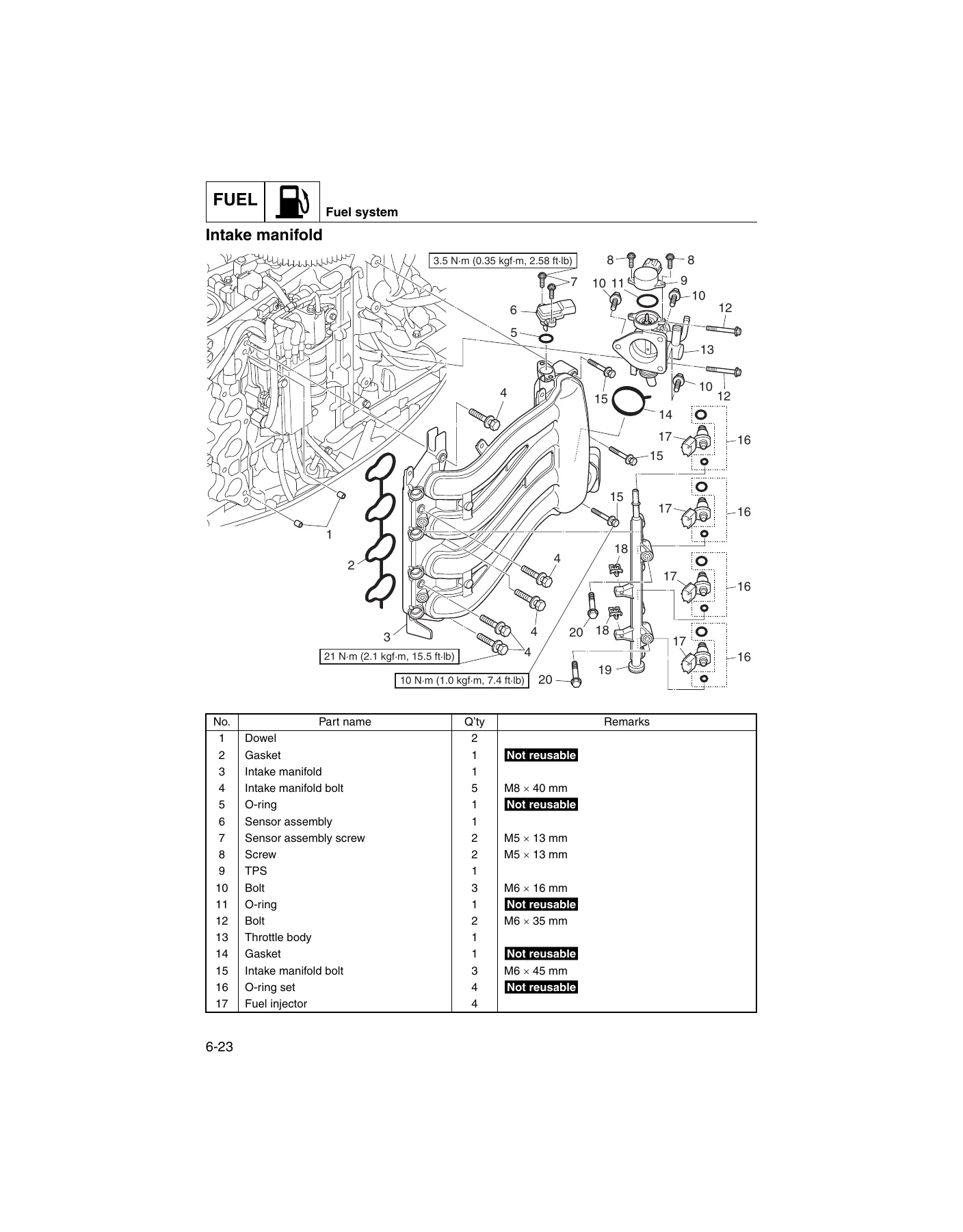
- Fuel system – hose routing, fuel system pressure reduction, disconnecting the quick connector, measuring fuel pressure, checking the pressure regulator, fuel filter assembly removal, checking the fuel joint, fuel filter assembly checks, disassembly, element check, fuel cup assembly, primer pump, assembly and installation, fuel pump assembly removal, checks, disassembly, diaphragm and valve, fuel strainer, assembly and installation, intake silencer, intake manifold, fuel injector removal and checks, throttle body, TPS, throttle link, throttle link rod adjustment, vapor separator draining, removal, checks and installation, vapor separator and high-pressure fuel pump disassembly, high-pressure fuel pump checks, float height adjustment and assembly
- Power unit – compression pressure check, oil pressure check, pulser coil air gap check and adjustment, valve clearance check and adjustment, power unit removal and installation, flywheel magnet and timing belt removal, stator assembly, timing belt and sprocket removal, checks and installation, engine ECM and starter motor, Rectifier Regulator and ignition coil, wiring harness removal and installation, shift bracket, cylinder head removal, bolt check and installation, camshaft and valve disassembly, cylinder head checks, valve spring, valve, valve guide replacement, valve seat checks and refacing, rocker arm and shaft, camshaft, spark plug, cylinder head anode, cylinder head assembly, exhaust cover removal, thermo sensor, oil pressure switch, oil filter, anode checks, thermostat, oil filter installation, exhaust cover installation, cylinder block disassembly, piston diameter, cylinder bore, piston ring, ring end gap, ring groove, ring side clearance, piston pin boss, piston pin, connecting rod checks, crankshaft, crankpin oil clearance, crankpin bearing selection, crankshaft journal oil clearance, crankshaft journal bearing selection, cylinder block assembly
- Lower unit – L-transom lower unit, X-transom lower unit, removal, propeller check, anode check, water pump and shift rod removal, oil seal housing disassembly, water pump and shift rod checks, oil seal housing assembly, propeller shaft housing removal, propeller shaft assembly disassembly, housing assembly disassembly, propeller shaft check, dog clutch, housing check, reverse gear, assembly, drive shaft and lower case removal, drive shaft disassembly, forward gear disassembly, lower case disassembly, pinion check, forward gear check, drive shaft check, forward gear assembly, drive shaft assembly, lower case assembly, drive shaft installation, propeller shaft housing installation, shift rod installation, water pump installation, air leakage check, lower unit installation, shimming workflow, shimming check sheet, forward gear backlash measurement before disassembly, shim location, pinion shim (T3) selection, pinion shim selection table, forward gear backlash measurement, forward gear shim (T1) adjustment and selection chart
- Bracket unit – friction plate removal, disassembly, assembly and installation, tiller handle disassembly and assembly, electrical component (multifunction) disassembly and assembly, shift rod and shift bracket disassembly and assembly, bottom cowling disassembly and assembly, upper case and mount removal and installation, upper case disassembly, drive shaft bushing check, upper case assembly, oil pan and exhaust manifold disassembly, checks, oil strainer, assembly, steering arm removal and installation, clamp bracket and swivel bracket removal, anode check, installation, trim sensor adjustment, PTT unit removal, anode check, installation, PTT motor removal, disassembly, armature check, brush check, assembly and installation, PTT gear pump disassembly, gear pump check, filter check, gear pump housing assembly, PTT cylinder, trim cylinder disassembly, tilt cylinder disassembly, PTT ram assembly disassembly, cylinder and piston checks, ram assembly, tilt cylinder and trim cylinder assembly, bleeding the PTT unit
- Maintenance – outline and maintenance interval charts, predelivery check covering battery, cooling water pilot hole, engine oil level, engine start switch and engine shut-off switch, fuel system, gear oil level, gear shift and throttle operation for remote control and tiller handle, outboard motor mounting height, PTT system, steering system, throttle and shift cables, test run, break-in schedule, after test run checks, general periodic maintenance covering anodes, battery, cooling water passage, engine idle speed, changing engine oil, engine oil level, replacing the oil filter, engine start and shut-off switches, fuel filter, fuel joint and hoses, changing gear oil, gear oil level, lubricating the outboard motor, propeller check, PTT fluid level and operation, shift cable adjustment, spark plug, timing belt check and replacement, thermostat, throttle link rod and throttle cable adjustment, top cowling, valve clearance and water pump
- Appendix – wiring diagram usage, engine control unit and fuel unit schematic, ignition unit schematic, charging unit and starting unit schematic, control unit schematic, colour code legend
Read together, these chapters give a technician a complete working picture of the F70A. The specification chapter establishes the numbers you are working to, the technical features chapter explains how the electronic control system, fuel injection, ignition and PTT hydraulics actually behave, the troubleshooting chapter tells you how to interrogate faults with YDIS or the diagnostic flash indicator, and the remaining chapters walk through the physical teardown and rebuild of every assembly from the top cowling down to the lower case gears.
Models and Serial Coverage
The manual covers the F70AET remote control model and the F70A tiller handle model. Approved model code and starting serial number are given as 6CJ and 1000001-. Both L (20 in) and X (25 in) transom height versions are documented, including the extension housing used on the X-transom lower unit.
Engineered Details You Will Use Repeatedly
- Valve clearance adjustment procedure with the specific cylinder sequence for the 1 and 4 marks on the driven sprocket
- Cylinder head bolt tightening in staged torque plus a two-stage 90 degree turn sequence
- Crankpin and crankshaft journal oil clearance checking with Plastigauge and bearing colour selection tables
- Pinion shim (T3) selection table keyed to the pinion height measurement and the stamped value on the lower case
- Forward gear shim (T1) selection chart for setting backlash after gear or bearing replacement
- Starter motor armature, commutator and brush wear limits
- PTT motor commutator and brush limits plus PTT unit bleeding sequence with the motor lead polarity table
- Fuel pressure figures for both the initial three-second prime and stabilised idle condition
- Trouble code table covering thermo sensor, knock sensor, TPS, battery voltage, intake temp, water in fuel, shift position, intake pressure, intake air passage, engine stop lanyard, overcooling and immobiliser
What This Manual Lets You Do
With this Yamaha F70A service manual in hand you can carry out scheduled maintenance from the maintenance interval charts, diagnose running faults using the YDIS or flash indicator procedures, pull and rebuild the power unit, service the cylinder head and valvetrain, recondition the lower unit with correct shimming, repair or overhaul the PTT system, and troubleshoot the electrical system down to individual sensor and relay level. Torque values, service limits, oil clearances, backlash figures, float heights, brush wear limits and pressure readings are all published in the specification and procedure pages rather than left to guesswork.
Complete PDF Bookmark Tree
Complete Bookmarks
The complete bookmarks in the “Yamaha F70A Outboard Service Manual 2010 – F70AET Repair & Workshop PDF” are as follows:
+Contentsp. 3
+General informationp. 5
+!Safety while workingp. 6
Rotating partp. 6
Hot partp. 6
Electric shockp. 6
Propellerp. 6
Handling of gasolinep. 6
Ventilationp. 6
Self-protectionp. 7
Working with cranep. 7
Handling of gas torchp. 7
Part, lubricant, and sealantp. 7
Handling of sealantp. 8
Special service toolp. 8
Tightening torquep. 8
Non-reusable partp. 8
Disassembly and assemblyp. 8
+How to use this manualp. 9
Manual formatp. 9
Abbreviationp. 10
+Lubricant, sealant, and thread locking agentp. 11
Special service toolp. 13
+Specificationp. 22
+Model featurep. 24
General featurep. 24
Model designationp. 25
Serial numberp. 25
+Model datap. 26
Dimension and weightp. 26
Performancep. 26
Power unitp. 26
Lower unitp. 27
Bracket unitp. 27
Fuel and oil requirementp. 27
Battery requirementp. 28
PTT fluid requirementp. 28
+Electrical system technical datap. 29
Ignition timing control systemp. 29
Fuel injection control systemp. 30
Engine speed control systemp. 30
PTT systemp. 31
Charging systemp. 31
Starting systemp. 31
Gauge/sensorp. 32
+Fuel system technical datap. 33
+Power unit technical datap. 34
Power unitp. 34
Cylinder head assemblyp. 34
Crankcase assemblyp. 35
+Lower unit technical datap. 37
+Bracket unit technical datap. 37
+Specified tightening torquep. 38
Rigging informationp. 38
Fuel systemp. 38
Power unitp. 38
Lower unitp. 39
Tiller handle modelp. 40
Bracket unitp. 40
PTT unitp. 40
General tightening torquep. 41
+Technical features and descriptionp. 43
+Electronic control systemp. 44
Engine ECM componentp. 45
Electronic fuel injection controlp. 47
Ignition timing controlp. 48
Engine speed controlp. 49
Knock controlp. 51
ISC Controlp. 51
Alert indicator, alert buzzer controlp. 51
Fail-safe controlp. 52
Y-COPp. 53
Power unitp. 54
+Fuel systemp. 55
+Lubrication systemp. 57
+Cooling systemp. 58
+Intake and exhaust systemp. 59
Intake and exhaust diagramp. 59
+PTT unitp. 60
Trim-up and tilt-up functionp. 60
Trim-down and tilt-down functionp. 61
Stationary conditionp. 62
Shock-absorbing functionp. 62
+Rigging informationp. 63
Outboard motor installationp. 64
+Dimensionp. 65
Exterior: F70AETp. 65
Exterior: F70A (tiller handle model)p. 66
Clamp bracketp. 67
Crate top cover pictograph descriptionp. 68
Uncrating procedurep. 69
Outboard motor mountingp. 70
+Rigging grommet mountingp. 72
Rigging grommet descriptionp. 72
Installing the shift cable and throttle cablep. 72
Installing the wiring harnessp. 74
Installing the 6Y8 Multifunction Meter harnessp. 75
Installing the remote control box and tachometerp. 76
+Optional equipmentp. 76
Installing the water pressure sensorp. 76
Installing the speed sensorp. 77
Installing the tiller handlep. 78
+Installing Y-COP (optional in non-European markets)p. 80
Registering the receiver ID to the ECMp. 80
Battery installationp. 81
+System diagramp. 82
Single outboard motor applicationp. 82
+Rigging recommendationp. 84
+Propeller selectionp. 84
Propeller sizep. 84
Selectionp. 84
+Troubleshootingp. 85
+YDISp. 86
Featurep. 86
Hardware requirementp. 86
Functionp. 87
Connecting the communication cable to the outboard motorp. 88
+Outboard motor troubleshootingp. 89
Troubleshooting procedurep. 89
Troubleshooting the power unit using the YDISp. 89
Trouble code and checking stepp. 91
Troubleshooting the power unit using the diagnostic flash indicatorp. 93
Troubleshooting the power unit (trouble code not detected)p. 94
Troubleshooting the PTT unitp. 98
Troubleshooting the lower unitp. 99
+Electrical systemp. 100
+Electrical component and wiring harness routingp. 102
Portp. 102
Starboardp. 104
Frontp. 105
Topp. 106
Bottom cowlingp. 107
Tiller handle (optional)p. 109
Circuit diagramp. 111
ECM coupler layoutp. 112
+Checking the electrical componentp. 113
Using the YDISp. 113
Measuring the peak voltagep. 113
Using the digital testerp. 114
+Engine control unit and componentp. 114
Checking the main relayp. 114
Checking the engine ECM circuitp. 115
Checking the TPSp. 116
Checking the ISCp. 117
Checking the oil pressure switchp. 118
Checking the alert indicator (tiller handle model)p. 119
Checking the alert buzzerp. 119
Checking the trolling switch (tiller handle model)p. 119
+Fuel control unit and componentp. 120
Checking the water detection switchp. 120
Checking the fuel injectorp. 121
Checking the high-pressure fuel pumpp. 122
Checking the vapor shut-off valvep. 123
+Charging unit and componentp. 124
Checking the lighting coil (stator assembly)p. 124
Checking the Rectifier Regulatorp. 125
+Ignition unit and componentp. 126
Checking the ignition sparkp. 126
Checking the spark plug wirep. 126
Checking the ignition coilp. 126
Checking the pulser coilp. 127
Checking the air temperature sensorp. 128
Checking the air pressure sensorp. 129
Checking the thermo sensorp. 130
Checking the knock sensorp. 131
Checking the neutral switchp. 131
Checking the engine shut-off switchp. 132
+Starting unit and componentp. 132
Checking the starter relayp. 132
Checking the engine start switchp. 133
Checking the neutral switch (tiller handle model)p. 133
Checking Y-COPp. 133
+Starter motorp. 135
Removing the starter motorp. 137
Checking the starter motor operationp. 137
Checking the magnet switchp. 137
Checking the starter motor pinionp. 137
Disassembling the starter motorp. 138
Checking the armature (starter motor)p. 139
Checking the brush holderp. 140
Assembling the starter motorp. 140
Installing the starter motorp. 142
+6Y8 Multifunction Meter sensorp. 142
Checking the water pressure sensor (optional)p. 142
Checking the speed sensor (optional)p. 143
+PTT electrical systemp. 145
Checking the PTT relayp. 145
Checking the PTT switch (bottom cowling)p. 146
Checking the PTT switch (tiller handle)p. 147
Checking the trim sensorp. 147
+Fuel systemp. 150
+Hose routingp. 152
Fuel hosep. 152
Blowby hose, vapor gas hose, and air hosep. 153
Cooling water hosep. 154
+Fuel systemp. 155
Reducing the fuel pressurep. 155
Disconnecting the quick connectorp. 155
Measuring the fuel pressurep. 155
Checking the pressure regulatorp. 156
+Fuel filter assemblyp. 158
Removing the fuel filter assemblyp. 160
Checking the fuel jointp. 160
Checking the fuel filter assemblyp. 161
Disassembling the fuel filter assemblyp. 161
Checking the fuel filter elementp. 161
Checking the fuel cup assemblyp. 162
Checking the primer pumpp. 162
Assembling the fuel filter assemblyp. 162
Installing the fuel filter assemblyp. 162
+Fuel pump assemblyp. 164
Removing the fuel pump assemblyp. 166
Checking the fuel pump assemblyp. 166
Disassembling the fuel pump assemblyp. 167
Checking the diaphragm and valvep. 167
Checking the fuel strainerp. 167
Assembling the fuel pump assemblyp. 168
Installing the fuel pump assemblyp. 169
+Intake silencerp. 170
Removing the intake silencerp. 172
Checking the ISC valvep. 172
Installing the intake silencerp. 172
+Intake manifoldp. 174
Removing the fuel injectorp. 176
Checking the fuel rail and fuel injectorsp. 176
Removing the intake manifoldp. 176
Checking the intake manifoldp. 177
Checking the throttle bodyp. 177
Checking the TPSp. 177
Installing the intake manifoldp. 177
Installing the fuel injectorp. 179
+Throttle link rodp. 181
Removing the throttle linkp. 182
Installing the throttle linkp. 182
Adjusting the throttle link rodp. 183
+Vapor separatorp. 185
Draining the fuelp. 187
Removing the vapor separatorp. 187
Checking the vapor shut-off valvep. 189
Installing the vapor separatorp. 189
+Vapor separator and high-pressure fuel pumpp. 192
Disassembling the vapor separatorp. 194
Checking the high-pressure fuel pumpp. 195
Checking the vapor separatorp. 195
Adjusting the float heightp. 195
Assembling the vapor separatorp. 195
+Power unitp. 198
+Power unit (check and adjustment)p. 200
Checking the compression pressurep. 200
Checking the oil pressurep. 200
Checking the pulser coil air gapp. 201
Adjusting the pulser coil air gapp. 201
Checking the valve clearancep. 201
Adjusting the valve clearancep. 203
+Power unit assemblyp. 204
Removing the power unitp. 206
Installing the power unitp. 208
+Flywheel magnet and timing beltp. 212
Removing the flywheel magnetp. 214
Removing the stator assemblyp. 214
Removing the timing belt and sprocketp. 215
Checking the timing belt and sprocketp. 216
Installing the sprocket and timing beltp. 216
Installing the stator assemblyp. 217
Installing the flywheel magnetp. 218
+Engine ECM and starter motorp. 220
Removing the starter motorp. 221
Remove the starter relayp. 221
Installing the starter relayp. 221
Installing the starter motorp. 222
+Rectifier Regulator and ignition coilp. 223
Removing the Rectifier Regulator and ignition coilp. 224
Installing the ignition coil and Rectifier Regulatorp. 224
+Wiring harnessp. 226
Removing the wiring harnessp. 229
Installing the wiring harnessp. 230
Shift bracketp. 232
+Cylinder headp. 233
Removing the cylinder headp. 234
Checking the cylinder head boltp. 234
Installing the cylinder headp. 234
+Camshaft and valvep. 237
Disassembling the cylinder headp. 239
Checking the cylinder headp. 240
Checking the valve springp. 240
Checking the valvep. 241
Checking the valve guidep. 241
Replacing the valve guidep. 241
Checking the valve seatp. 242
Refacing the valve seatp. 243
Checking the rocker arm and rocker arm shaftp. 245
Checking the camshaftp. 245
Checking the spark plugp. 246
Checking the cylinder head anodep. 246
Assembling the cylinder headp. 246
+Exhaust coverp. 249
Removing the exhaust coverp. 251
Removing the thermo sensorp. 251
Removing the oil pressure switchp. 251
Removing the oil filterp. 251
Checking the exhaust cover anodep. 252
Checking the thermostatp. 252
Installing the oil filterp. 252
Installing the oil pressure switchp. 252
Installing the thermo sensorp. 253
Installing the exhaust coverp. 253
+Cylinder blockp. 255
Disassembling the cylinder blockp. 256
Checking the piston diameterp. 257
Checking the cylinder borep. 257
Checking the piston ringp. 257
Checking the piston ring end gapp. 257
Checking the piston ring groovep. 258
Checking the piston ring side clearancep. 258
Checking the piston pin bossp. 258
Checking the piston pinp. 258
Checking the connecting rod small end inside diameter and big end inside diameterp. 258
Checking the connecting rod big end side clearancep. 259
Checking the crankshaftp. 259
Checking the crankpin oil clearancep. 259
Selecting the crankpin bearingp. 261
Checking the crankshaft journal oil clearancep. 261
Selecting the crankshaft journal bearingp. 262
Assembling the cylinder blockp. 263
+Lower unitp. 268
+Lower unit (L-transom model)p. 270
Removing the lower unitp. 272
Checking the propellerp. 272
Checking the lower unit anodep. 272
+Lower unit (X-transom model)p. 273
Removing the lower unitp. 275
Checking the propellerp. 275
Checking the lower unit anodep. 275
+Water pump and shift rodp. 276
Removing the water pump and shift rodp. 278
Disassembling the oil seal housingp. 278
Checking the water pump and shift rodp. 279
Assembling the oil seal housingp. 279
+Propeller shaft housingp. 280
Removing the propeller shaft housing assemblyp. 282
Disassembling the propeller shaft assemblyp. 282
Disassembling the propeller shaft housing assemblyp. 283
Checking the propeller shaftp. 283
Checking the dog clutchp. 283
Checking the propeller shaft housingp. 283
Checking the reverse gearp. 283
Assembling the propeller shaft assemblyp. 283
Assembling the propeller shaft housing assemblyp. 284
+Drive shaft and lower casep. 286
Removing the drive shaftp. 287
Disassembling the drive shaftp. 287
Disassembling the forward gearp. 287
Disassembling the lower casep. 287
Checking the pinionp. 288
Checking the forward gearp. 288
Checking the drive shaftp. 288
Assembling the forward gearp. 288
Assembling the drive shaftp. 289
Assembling the lower casep. 289
Installing the drive shaftp. 291
Installing the propeller shaft housing assemblyp. 291
Installing the shift rodp. 292
Installing the water pumpp. 293
Checking the lower unit for air leakagep. 294
Installing the lower unit (L-transom model)p. 294
Installing the lower unit (X-transom model)p. 295
+Shimmingp. 297
Shimming workflowp. 297
Shimming check sheetp. 298
Measuring the forward gear backlash before disassemblyp. 299
Shimmingp. 302
Shim locationp. 302
Selecting the pinion shim (T3)p. 303
Pinion shim (T3) selection tablep. 306
Measuring the forward gear backlashp. 308
Adjusting the forward gear shim thickness (T1)p. 308
Forward gear shim (T1) selection chartp. 310
+Bracket unitp. 312
+Friction platep. 314
Removing the friction platep. 316
Disassembling the friction platep. 316
Assembling the friction platep. 316
Installing the friction plate assemblyp. 317
+Tiller handlep. 318
Disassembling the tiller handlep. 321
Assembling the tiller handlep. 322
+Electrical component (multifunction)p. 326
Disassembling the electrical component (multifunction)p. 327
Assembling the electrical component (multifunction)p. 327
+Shift rod and shift bracketp. 329
Disassembling the shift rodp. 330
Assembling the shift rodp. 330
+Bottom cowlingp. 331
Disassembling the bottom cowlingp. 334
Assembling the bottom cowlingp. 334
+Upper case and mountp. 337
Removing the upper casep. 339
Installing the upper casep. 339
+Upper casep. 341
Disassembling the upper casep. 342
Checking the drive shaft bushingp. 342
Assembling the upper casep. 342
+Oil pan and exhaust manifoldp. 344
Disassembling the oil pan and exhaust manifoldp. 346
Checking the oil pan and exhaust manifoldp. 347
Checking the oil strainerp. 347
Assembling the oil pan and exhaust manifoldp. 347
+Steering armp. 349
Removing the steering armp. 350
Installing the steering armp. 350
+Clamp bracket and swivel bracketp. 352
Removing the clamp bracketp. 354
Checking the clamp bracket anodep. 354
Installing the clamp bracketp. 354
Adjusting the trim sensorp. 356
+PTT unitp. 357
Removing the PTT unitp. 358
Checking the PTT unit anodep. 358
Installing the PTT unitp. 358
+PTT motorp. 360
Removing the PTT motorp. 362
Disassembling the PTT motorp. 362
Checking the armature (PTT motor)p. 362
Checking the brushp. 363
Assembling the PTT motorp. 364
Installing the PTT motorp. 364
+PTT gear pumpp. 366
Disassembling the gear pump assemblyp. 369
Checking the gear pumpp. 369
Checking the filterp. 370
Assembling the gear pump housingp. 370
+PTT cylinderp. 372
Disassembling the trim cylinderp. 374
Disassembling the tilt cylinderp. 374
Disassembling the PTT ram assemblyp. 374
Checking the PTT cylinder and pistonp. 375
Assembling the PTT ram assemblyp. 375
Assembling the tilt cylinderp. 376
Assembling the trim cylinderp. 377
Bleeding the PTT unitp. 378
+Maintenancep. 380
+Outlinep. 382
Maintenance interval chart 1p. 382
Maintenance interval chart 2p. 383
+Predelivery checkp. 384
Checking the batteryp. 384
Checking the cooling water pilot holep. 384
Checking the engine oil levelp. 385
Checking the engine start switch and engine shut-off switchp. 385
Checking the fuel systemp. 386
Checking the gear oil levelp. 386
Checking the gear shift and throttle operation (remote control)p. 386
Checking the gear shift and throttle operation (tiller handle)p. 386
Checking the outboard motor mounting heightp. 386
Checking the PTT systemp. 387
Checking the steering systemp. 387
Checking the throttle cable and shift cable (remote control)p. 387
Checking the throttle cable and shift cable (tiller handle)p. 387
Test runp. 388
Break-inp. 388
After test runp. 388
+General periodic maintenancep. 388
Checking the anodep. 388
Checking the batteryp. 389
Checking the cooling water passagep. 389
Checking the engine idle speedp. 389
Changing the engine oilp. 389
Checking the engine oil levelp. 390
Replacing the oil filterp. 390
Checking the engine start switch and engine shut-off switchp. 391
Checking the fuel filterp. 391
Checking the fuel joint and fuel hosesp. 391
Changing the gear oilp. 391
Checking the gear oil levelp. 392
Lubricating the outboard motorp. 392
Checking the propellerp. 393
Checking the PTT fluid levelp. 393
Checking the PTT operationp. 394
Adjusting the shift cablep. 394
Checking the spark plugp. 394
Checking the timing beltp. 394
Replacing the timing beltp. 394
Checking the thermostatp. 394
Adjusting the throttle link rod and throttle cablep. 394
Checking the top cowlingp. 394
Checking the valve clearancep. 395
Checking the water pumpp. 395
Indexp. 396
+Appendixp. 403
+Wiring diagramp. 404
How to use the wiring diagramp. 404
Engine control unit and fuel unitp. 404
Ignition unitp. 408
Charging unit and starting unitp. 410
Control unitp. 412
Engine control unit and fuel unitp. 407
Charging unit and starting unitp. 411
Ignition unitp. 409
Working from the correct procedures and specifications matters on an outboard because the consequences of getting it wrong are expensive – a mis-shimmed lower unit destroys gears, an incorrectly staged cylinder head torque distorts the head, and a fuel system opened without depressurising sprays pressurised gasoline. This manual gives you the sequence, the values and the checks in the order Yamaha intends them to be carried out.
Delivery is instant. Once your order is complete the PDF is available for immediate download – no shipping, no waiting, no physical book to lose in the workshop. Open it on a laptop, tablet or phone at the bench, print only the pages you need for a job, and keep the file for as long as you own the motor.
Who This Is For
Marine technicians working on Yamaha four-stroke outboards, dealers supporting the F70AET and tiller handle F70A, and owners who want the factory procedure rather than a generic guide. If you are servicing, repairing or rebuilding an F70A, this is the document that tells you how.


Reviews
There are no reviews yet.