★ TRUSTED BY 321,897+ PROFESSIONALS WORLDWIDE
🏒
Trusted Business
Verified & Licensed
πŸ›‘οΈ
Virus Free Files
100% Safe Downloads
πŸ”’
Secure Payment
SSL Protected
⚑
Instant Delivery
Available Immediately
Sale!

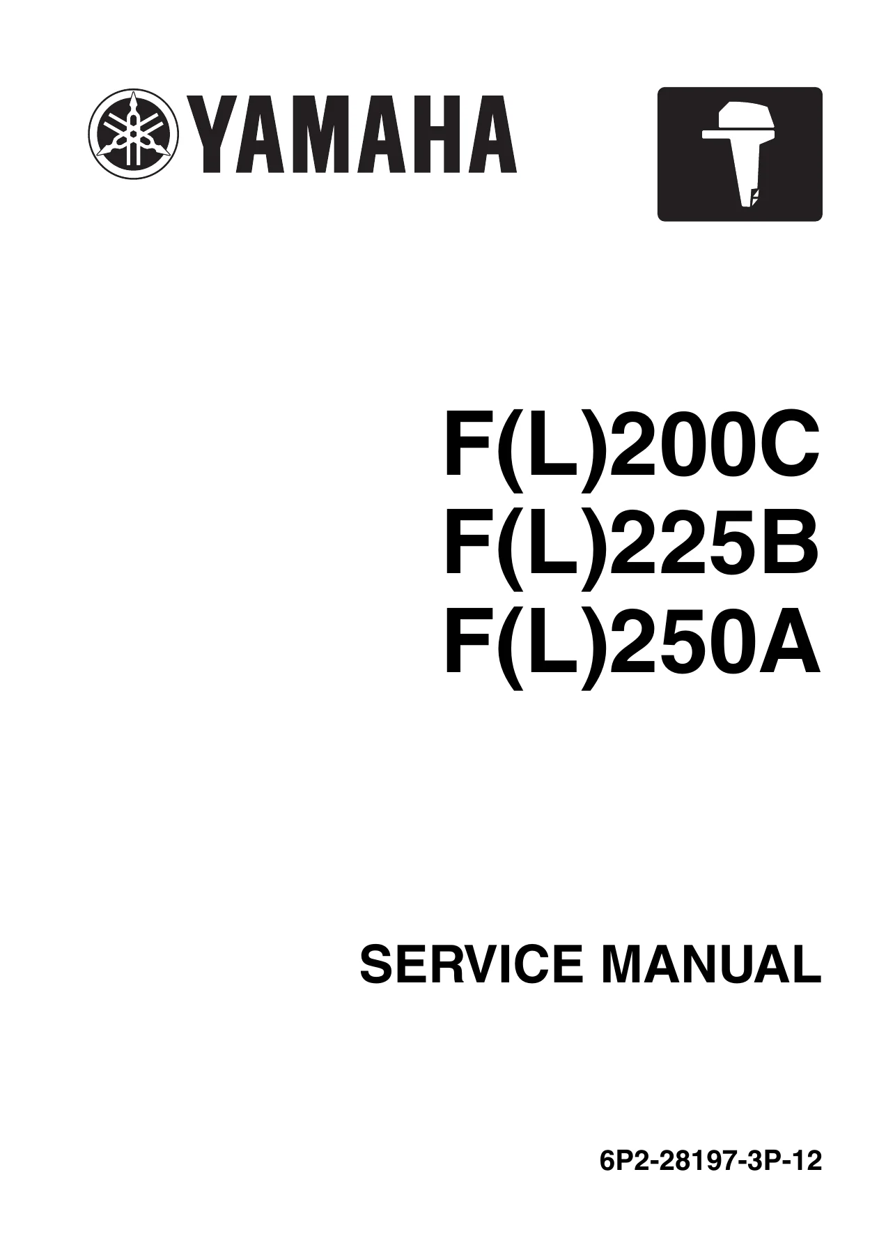
Yamaha F(L)200C F(L)225B F(L)250A Outboard Service Manual 2012 – 6P2-28197-3P-12 PDF

Original price was: $39.95.Current price is: $23.95.

Complete Yamaha service manual for the F(L)200C, F(L)225B and F(L)250A four-stroke outboard motors. Document 6P2-28197-3P-12, 2nd Edition, November 2012. Covers the full 3352 cm3 V6 powerhead, fuel injection, electrical system, lower unit shimming, PTT hydraulics and scheduled maintenance.

⚑
Instant PDF Download
Available immediately
πŸ’Ύ
Save to Your Device
Download & keep forever
πŸ›‘οΈ
Antivirus Scanned
100% virus-free
🌍
Trusted Worldwide
175,000+ customers

Description

Yamaha F(L)200C, F(L)225B and F(L)250A Service Manual – Document 6P2-28197-3P-12

This is the full Yamaha service manual for the F(L)200C, F(L)225B and F(L)250A four-stroke outboard motors, covering both the standard rotation models and the counter-rotation “L” variants. Written by Yamaha Motor Co., Ltd. for its dealer network and trained marine mechanics, it walks through the entire machine – the 3352.0 cm3 60-degree V6 powerhead, the electronic fuel injection and ignition control system, the VCT assemblies, the mid-section, the lower unit and the power trim and tilt hydraulics.

Whether you are servicing your own boat, running a small marine workshop or simply want the correct torque figure before you put a spanner on a $20,000 outboard, this Yamaha F(L)200C F(L)225B F(L)250A service manual gives you the procedure, the specification and the illustration to do the job properly the first time.

File Details

  • Manual type: Service manual (workshop repair manual)
  • Brand / manufacturer: Yamaha Motor Co., Ltd.
  • Models covered: F200CET, FL200CET, F225BET, FL225BET, F250AET, FL250AET
  • Document number: 6P2-28197-3P-12
  • Edition: 2nd Edition, November 2012
  • Language: English
  • File format: PDF

Chapters Covered

  • General Information – safety while working, rotating parts, hot parts, electric shock, propeller handling, gasoline handling, ventilation, self-protection, crane work, gas torch handling, sealants, tightening torque, non-reusable parts, how to use the manual, abbreviations, symbols and special service tools
  • Specification – model data, dimensions and weight, performance, power unit data, lower unit data, bracket unit data, fuel and oil requirements, battery and PTT fluid requirements, electrical technical data, specified tightening torques and general tightening torque
  • Technical Features and Description – electronic control system, actuator/sensor/switch layout, electronic fuel injection control, digital ignition control, VCT control, knock control, over-rev and alert control, ETV control, fail-safe control, power unit system, shimless valve lifters, fuel system, blowby gas reburning, vapor gas treatment, lubrication, cooling, intake and exhaust, SDS propeller
  • Rigging Information – outboard motor installation, external dimensions, clamp bracket, crate top cover pictographs, uncrating, motor mounting, rigging grommet, shift and throttle cable installation, wiring harness, isolator lead, battery cable, speed sensor, water pressure sensor, remote control box and switch panel, battery installation and cable routing, system diagrams, rigging recommendations, propeller selection
  • Troubleshooting – YDIS feature and function, connecting the communication cable, troubleshooting procedure, power unit troubleshooting with YDIS, trouble code and checking step tables, diagnostic flash indicator, power unit troubleshooting without trouble codes, PTT unit troubleshooting, lower unit troubleshooting
  • Electrical System – wiring harness routing (port, starboard, rear, top, bottom cowling), circuit diagram, ECM coupler layout, checking electrical components, main relay, engine ECM circuit, APS and APS circuit, ETV and TPS, ETV motor relay, cam position sensors, OCV, oil pressure sensor, water pressure sensor, speed sensor, water detection switch, fuel injectors, low- and high-pressure fuel pumps, high-pressure fuel pump relay, vapor shut-off valve, lighting coil, Rectifier Regulator, ignition spark and coils, pulser coil, air temperature sensor, air pressure sensor, engine temperature sensor, thermoswitch, shift cut switch, neutral switch, knock sensor, engine shut-off switch, starter relay, engine start switch, starter motor disassembly and assembly, PTT relay, PTT switch and trim sensor
  • Fuel System – hose routing for fuel, blowby, vapor gas and cooling water, reducing fuel pressure, quick connector procedures, measuring fuel pressure, pressure regulator, fuel filter assembly, intake manifold and silencer, throttle body, canister and surge tank, low-pressure fuel pump, primer pump, vapor separator and high-pressure fuel pump, fuel injectors and fuel rails
  • Power Unit – compression pressure, oil pressure, pulser coil air gap, valve clearance check and adjustment, power unit removal and installation, flywheel magnet, wiring harness, starter motor, fuse box, junction box, Rectifier Regulator, engine ECM, timing belt, cylinder head covers, camshafts, driven sprockets, VCT assemblies, exhaust covers, cylinder heads, valve guides and seats, cooling water passage cover, knock sensor, crankcase, oil pump, cylinder block, pistons, connecting rods, crankshaft, bearings and shimming
  • Lower Unit – regular and counter rotation models for F200C/F225B and F250A, propeller removal, SDS propeller assembly, water pump and shift rod, propeller shaft housing, drive shaft, lower case, forward and reverse gear, oil seal housing, air leakage check, shimming workflow and check sheets, pinion shim (T3), propeller shaft shim (T4), forward gear shim (T1/T2) and reverse gear shim (T2/T1) selection charts
  • Bracket Unit – shift rod and shift bracket, PTT switch and cowling lock lever, bottom cowling, upper case and mounts, upper case internals, oil pan and exhaust manifold, oil strainer, steering arm, clamp bracket and swivel bracket, trim sensor adjustment, PTT unit, PTT motor, PTT gear pump, PTT cylinder, tilt ram and trim ram
  • Maintenance – predelivery check, maintenance charts 1 and 2, battery, cooling water pilot hole, engine oil level, engine start and shut-off switch, fuel system, gear oil level, gear shift and throttle operation, mounting height, PTT system, steering, cables, test run and break-in, general periodic maintenance, anodes, cooling water passages, idle speed, engine oil and filter, fuel filter, gear oil change, OCV filter, greasing, PCV, PTT fluid, propeller, shift and throttle cable adjustment, spark plugs, timing belt, thermostat, top cowling, valve clearance and water pump
  • Appendix – wiring diagrams for the engine control unit, fuel unit, ignition unit, charging and starting unit and PTT unit and control unit, plus the wiring diagram colour code legend

Complete PDF Bookmark Tree

Complete Bookmarks

The complete bookmarks in the β€œYamaha F(L)200C F(L)225B F(L)250A Outboard Service Manual 2012 – 6P2-28197-3P-12 PDF” are as follows:

Contentsp. 3
General informationp. 5
Safety while workingp. 6
Rotating partp. 6
Hot partp. 6
Electric shockp. 6
Propellerp. 6
Handling of gasolinep. 6
Ventilationp. 6
Self-protectionp. 7
Working with cranep. 7
Handling of gas torchp. 7
Part, lubricant, and sealantp. 7
Handling of sealantp. 7
Special service toolp. 8
Tightening torquep. 8
Non-reusable partp. 8
Disassembly and assemblyp. 8
How to use this manualp. 9
Manual formatp. 9
Abbreviationp. 10
Lubricant, sealant, and thread locking agentp. 12
Symbolp. 12
Special service toolp. 14
Specificationp. 22
Model featuresp. 24
General featurep. 24
Model designationp. 25
Serial numberp. 26
Model datap. 27
Dimension and weightp. 27
Performancep. 27
Power unitp. 28
Lower unitp. 29
Bracket unitp. 29
Fuel and oil requirementp. 29
Battery requirementp. 31
PTT fluid requirementp. 31
Electrical system technical datap. 32
Ignition timing control systemp. 32
Fuel injection control systemp. 34
Engine speed control systemp. 35
VCT systemp. 37
PTT systemp. 37
Charging systemp. 38
Starting systemp. 39
Gauge/sensorp. 39
Fuel system technical datap. 41
Fuel systemp. 41
Power unit technical datap. 42
Power unitp. 42
Cylinder head assemblyp. 43
Crankcase assemblyp. 45
Lower unit technical datap. 48
Lower unit assembly (regular rotation model)p. 48
Lower unit assembly (counter rotation model)p. 48
Bracket unit technical datap. 49
PTT systemp. 49
Specified tightening torquep. 50
Rigging informationp. 50
Fuel systemp. 50
Power unitp. 50
Lower unit (regular rotation model)p. 52
Lower unit (counter rotation model)p. 52
Bracket unitp. 52
PTT unitp. 53
General tightening torquep. 54
Technical features and descriptionp. 55
Electronic control systemp. 56
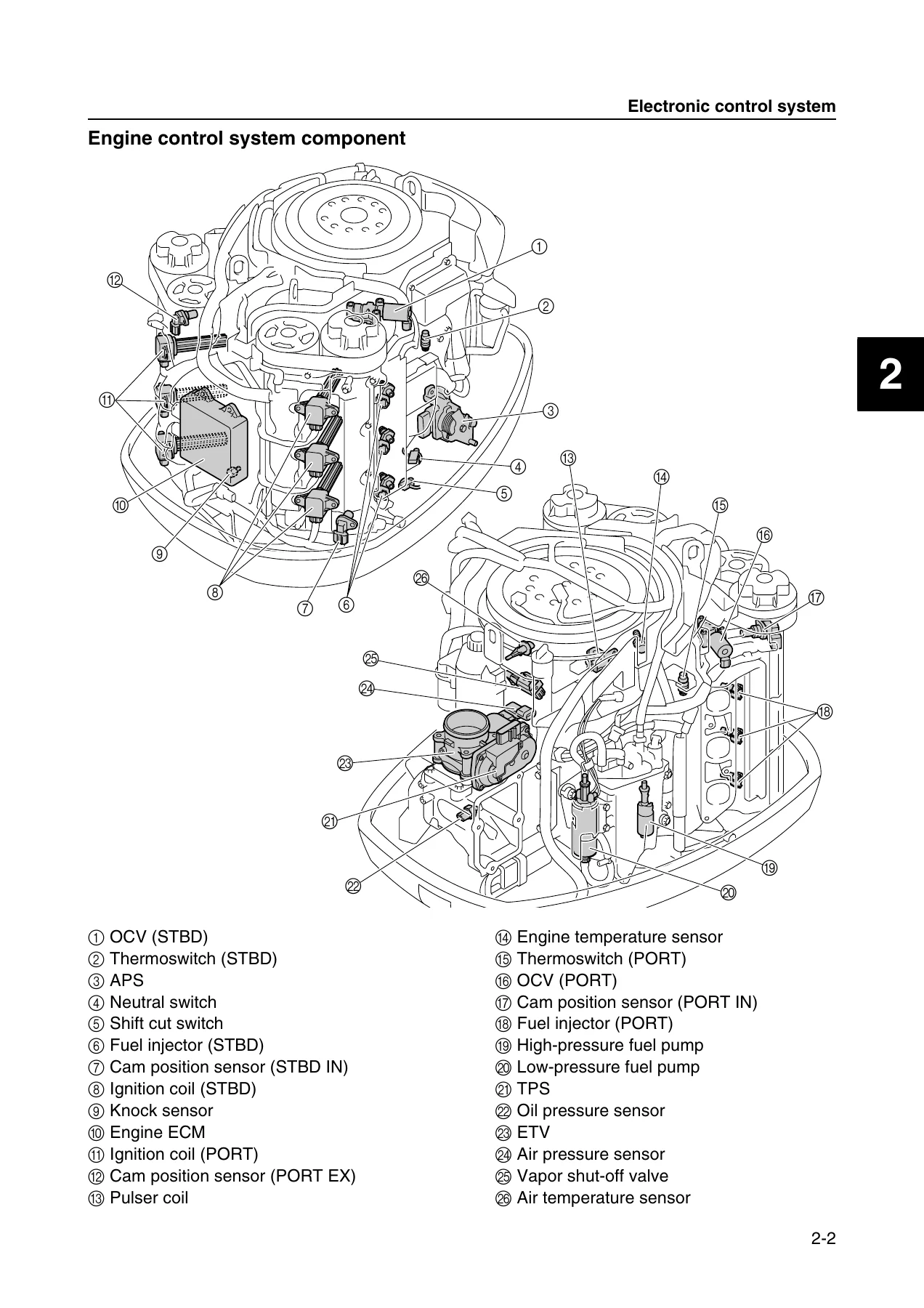
Engine control system componentp. 57
Actuator, sensor, and switchp. 58
Electronic fuel injection controlp. 59
Digital ignition controlp. 60
VCT controlp. 61
Knock controlp. 62
Over-rev control and alert controlp. 63
ETV controlp. 64
Fail-safe controlp. 65
Power unit systemp. 66
Shimless valve lifterp. 66
Fuel systemp. 67
Fuel diagramp. 67
Blowby gas reburning systemp. 69
Vapor gas treatmentp. 70
Lubrication systemp. 71
Lubrication diagramp. 71
Cooling systemp. 72
Cooling diagramp. 72
Intake and exhaust systemp. 76
Intake and exhaust diagramp. 76
Lower unitp. 77
Propeller (Shift Dampener System [SDS] propeller)p. 77
Rigging informationp. 79
Outboard motor installationp. 80
External dimensionsp. 81
F(L)200CET, F(L)225BET, F(L)250AETp. 81
Clamp bracketp. 82
Crate top cover pictograph descriptionp. 83
Uncrating procedurep. 84
Outboard motor mountingp. 85
Rigging grommet mountingp. 87
Rigging grommet descriptionp. 87
Installing the shift cable and throttle cablep. 87
Installing the wiring harnessp. 90
Installing the isolator lead (optional)p. 90
Installing the battery cablep. 90
Installing the speed sensor (optional)p. 91
Installing the water pressure sensor (optional)p. 92
Installing the rigging grommetp. 93
Remote control box and switch panel installationp. 93
Battery installationp. 94
Battery cable routing without house (accessory) batteryp. 94
Battery cable routing with house (accessory) batteryp. 96
System diagramp. 100
Single outboard motor applicationp. 100
Twin outboard motor applicationp. 102
Triple outboard motor applicationp. 104
Rigging recommendationp. 106
Extension length recommendation for battery cablep. 106
Propeller selectionp. 107
Propeller sizep. 107
Selectionp. 107
Troubleshootingp. 111
YDISp. 112
Featurep. 112
Hardware requirementp. 112
Functionp. 113
Connecting the communication cable to the outboard motorp. 116
Outboard motor troubleshootingp. 117
Troubleshooting procedurep. 117
Troubleshooting the power unit using the YDISp. 117
Trouble code and checking stepp. 120
Troubleshooting the power unit using the diagnostic flash indicatorp. 129
Troubleshooting the power unit (trouble code not detected)p. 130
Troubleshooting the PTT unitp. 136
Troubleshooting the lower unitp. 137
Electrical systemp. 138
Electrical componentp. 140
Portp. 140
Starboardp. 141
Fuse holderp. 142
Rearp. 143
Topp. 144
Wiring harness routingp. 145
Portp. 145
Starboardp. 148
Rearp. 151
Topp. 154
Bottom cowlingp. 157
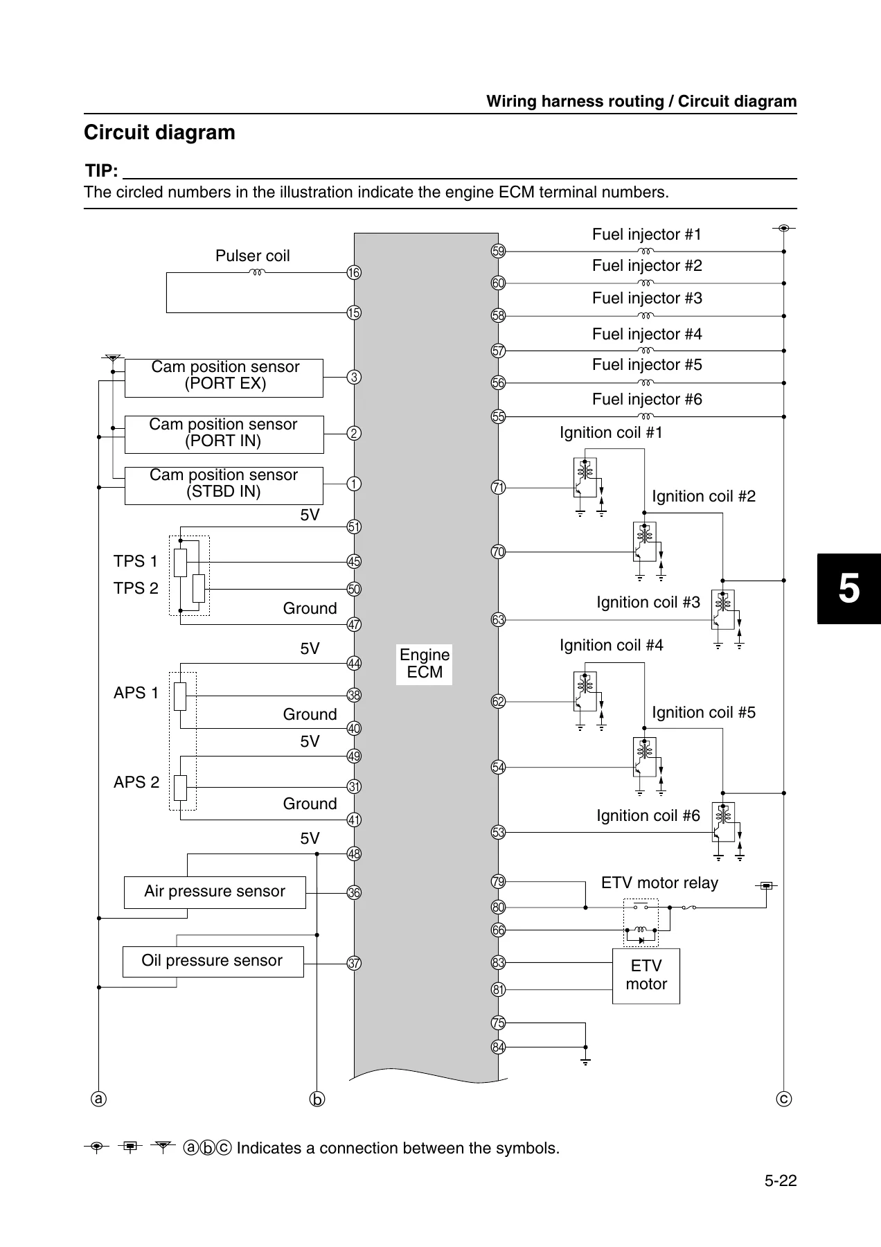
Circuit diagramp. 161
ECM coupler layoutp. 163
Checking the electrical componentp. 165
Using the YDISp. 165
Measuring the peak voltagep. 165
Using the digital testerp. 166
Engine control system and componentp. 166
Checking the main relayp. 166
Checking the engine ECM circuitp. 167
Checking the APSp. 168
Checking the APS circuitp. 169
Checking the ETV and TPSp. 170
Checking the ETV motor relayp. 171
Checking the ETV and TPS circuitp. 172
Checking the cam position sensorp. 173
Checking the OCVp. 176
Checking the oil pressure sensorp. 178
Checking the water pressure sensor (optional)p. 179
Checking the speed sensor (optional)p. 180
Fuel control unit and componentp. 181
Checking the water detection switchp. 181
Checking the fuel injectorp. 183
Checking the low-pressure fuel pump and high-pressure fuel pumpp. 184
Checking the high-pressure fuel pump relayp. 186
Checking the vapor shut-off valvep. 186
Charging unit and componentp. 188
Checking the lighting coilp. 188
Checking the Rectifier Regulatorp. 189
Ignition unit and componentp. 191
Checking the ignition sparkp. 191
Checking the ignition coilp. 192
Checking the pulser coilp. 193
Checking the air temperature sensorp. 194
Checking the air pressure sensorp. 195
Checking the engine temperature sensorp. 197
Checking the thermoswitchp. 198
Checking the shift cut switchp. 199
Checking the neutral switchp. 201
Checking the knock sensorp. 202
Checking the engine shut-off switchp. 203
Starting unit and componentp. 203
Checking the starter relayp. 203
Checking the engine start switchp. 204
Starter motorp. 205
Removing the starter motorp. 207
Checking the starter motor pinionp. 207
Disassembling the starter motorp. 207
Checking the armature (starter motor)p. 209
Checking the brush holder and brushp. 209
Assembling the starter motorp. 210
Installing the starter motorp. 212
PTT electrical systemp. 212
Checking the PTT relayp. 212
Checking the PTT switch (bottom cowling)p. 213
Checking the trim sensorp. 214
Fuel systemp. 216
Hose routingp. 218
Fuel hose and blowby hosep. 218
Vapor gas hosep. 220
Cooling water hosep. 222
Fuel systemp. 224
Reducing the fuel pressurep. 224
Disconnecting the quick connectorp. 224
Connecting the quick connectorp. 225
Measuring the fuel pressurep. 225
Checking the pressure regulatorp. 227
Fuel filter assemblyp. 228
Removing the fuel filter assemblyp. 230
Checking the fuel filter assemblyp. 230
Disassembling the fuel filter assemblyp. 231
Checking the fuel filter elementp. 231
Checking the fuel cup assemblyp. 231
Assembling the fuel filter assemblyp. 231
Installing the fuel filter assemblyp. 231
Intake manifoldp. 232
Removing the intake silencerp. 234
Removing the intake manifoldp. 234
Checking the intake manifoldp. 235
Checking the air temperature sensorp. 235
Installing the intake manifoldp. 235
Installing the intake silencerp. 236
Throttle bodyp. 238
Removing the throttle body assemblyp. 240
Checking the canister check valvep. 240
Checking the vacuum hosep. 241
Installing the throttle body assemblyp. 241
Canister, throttle body, and surge tankp. 243
Removing the canister, throttle body, and surge tankp. 245
Checking the ETVp. 245
Checking the air pressure sensorp. 245
Checking the vapor shut-off valvep. 245
Checking the canisterp. 245
Installing the canister, throttle body, and surge tankp. 246
Low-pressure fuel pumpp. 248
Removing the low-pressure fuel pumpp. 249
Checking the low-pressure fuel pumpp. 249
Checking the primer pumpp. 249
Installing the low-pressure fuel pumpp. 250
Vapor separatorp. 251
Draining the fuelp. 252
Removing the vapor separatorp. 252
Installing the vapor separatorp. 252
Vapor separator and high-pressure fuel pumpp. 254
Disassembling the vapor separatorp. 256
Checking the high-pressure fuel pumpp. 257
Checking the vapor separatorp. 257
Checking the check valvep. 257
Assembling the vapor separatorp. 258
Fuel injectorp. 260
Removing the fuel injectorp. 262
Checking the fuel railp. 262
Checking the quick connectorp. 263
Installing the fuel injectorp. 263
Power unitp. 265
Power unit (check and adjustment)p. 268
Checking the compression pressurep. 268
Checking the oil pressurep. 268
Checking the pulser coil air gapp. 268
Checking the valve clearancep. 269
Adjusting the valve clearancep. 271
Power unit assemblyp. 273
Removing the power unitp. 275
Installing the power unitp. 278
Flywheel magnetp. 282
Removing the flywheel magnetp. 283
Checking the pulser coilp. 284
Installing the flywheel magnetp. 284
Wiring harnessp. 286
Removing the wiring harnessp. 287
Installing the wiring harnessp. 290
Starter motorp. 294
Removing the starter motorp. 295
Installing the starter motorp. 295
Fuse boxp. 296
Junction boxp. 297
Removing the Rectifier Regulatorp. 299
Checking the Rectifier Regulator anodep. 299
Removing the junction boxp. 299
Installing the junction boxp. 300
Installing the Rectifier Regulatorp. 300
Engine ECMp. 302
Removing the engine ECMp. 303
Installing the engine ECMp. 303
Timing beltp. 304
Removing the timing beltp. 305
Checking the timing beltp. 306
Installing the timing beltp. 306
Cylinder headp. 309
Removing the cylinder head coverp. 311
Checking the spark plugp. 311
Installing the cylinder head coverp. 311
Camshaftp. 313
Removing the driven sprocket and camshaftp. 315
Checking the sprocketp. 316
Checking the valve lifterp. 316
Checking the camshaftp. 317
Installing the camshaft and driven sprocketp. 317
Exhaust coverp. 323
Removing the exhaust coverp. 324
Checking the exhaust cover anodep. 324
Installing the exhaust coverp. 324
Cylinder headp. 325
Removing the cylinder headp. 328
Disassembling the cylinder headp. 328
Checking the cylinder headp. 329
Checking the valve springp. 329
Checking the valvep. 329
Checking the valve guidep. 330
Replacing the valve guidep. 330
Checking the valve seatp. 331
Refacing the valve seatp. 332
Checking the cylinder head anodep. 334
Assembling the cylinder headp. 334
Installing the cylinder headp. 335
Cooling water passage coverp. 337
Removing the cooling water passage coverp. 339
Checking the cooling water passage cover anodep. 339
Checking the knock sensorp. 339
Installing the cooling water passage coverp. 339
Crankcasep. 341
Removing the oil filter bracketp. 343
Removing the oil pump assemblyp. 343
Removing the crankcase coverp. 343
Disassembling the oil pump assemblyp. 344
Checking the oil pump assemblyp. 344
Assembling the oil pump assemblyp. 344
Installing the crankcase coverp. 345
Installing the oil pump assemblyp. 345
Installing the oil filter bracketp. 346
Cylinder blockp. 348
Disassembling the cylinder blockp. 351
Checking the thermostatp. 352
Checking the piston diameterp. 353
Checking the cylinder borep. 353
Checking the piston ringp. 353
Checking the piston ring end gap (reference)p. 353
Checking the piston ring groovep. 354
Checking the piston ring side clearancep. 354
Checking the piston pin boss inside diameterp. 354
Checking the piston pinp. 354
Checking the connecting rod small end inside diameter and big end inside diameterp. 355
Checking the connecting rod big end side clearancep. 355
Checking the crankshaftp. 355
Checking the crankcase boltp. 356
Checking the crankpin oil clearancep. 356
Selecting the crankpin bearingp. 357
Checking the crankshaft journal oil clearancep. 358
Selecting the crankshaft journal bearingp. 359
Crankshaft journal bearing selection tablep. 361
Checking the cylinder block anodep. 362
Assembling the cylinder blockp. 362
Lower unitp. 368
Lower unit (F200C and F225B)p. 372
Removing the lower unitp. 375
Disassembling the propeller (Shift Dampener System [SDS] propeller)p. 375
Checking the propellerp. 375
Checking the lower unit anodep. 376
Assembling the propeller (Shift Dampener System [SDS] propeller)p. 376
Lower unit (F250A)p. 378
Removing the lower unitp. 381
Disassembling the propeller (Shift Dampener System [SDS] propeller)p. 381
Checking the propellerp. 381
Checking the lower unit anodep. 381
Assembling the propeller (Shift Dampener System [SDS] propeller)p. 381
Water pump and shift rod (F200C and F225B)p. 382
Removing the water pump and shift rodp. 384
Disassembling the water pump housingp. 384
Checking the water pump and shift rodp. 384
Assembling the water pump housingp. 385
Water pump and shift rod (F250A)p. 386
Removing the water pump and shift rodp. 388
Disassembling the water pump housingp. 388
Checking the water pump and shift rodp. 388
Assembling the water pump housingp. 388
Propeller shaft housing (F200C and F225B)p. 389
Removing the propeller shaft housing assemblyp. 391
Disassembling the propeller shaft assemblyp. 391
Disassembling the propeller shaft housing assemblyp. 391
Checking the propeller shaft housingp. 392
Checking the propeller shaftp. 392
Assembling the propeller shaft assemblyp. 392
Assembling the propeller shaft housing assemblyp. 393
Propeller shaft housing (F250A)p. 395
Removing the propeller shaft housing assemblyp. 397
Disassembling the propeller shaft assemblyp. 397
Disassembling the propeller shaft housing assemblyp. 397
Checking the propeller shaft housingp. 397
Checking the propeller shaftp. 397
Assembling the propeller shaft assemblyp. 397
Assembling the propeller shaft housing assemblyp. 398
Drive shaft and lower case (F200C and F225B)p. 399
Removing the drive shaftp. 400
Disassembling the oil seal housingp. 400
Disassembling the forward gearp. 400
Disassembling the lower casep. 400
Checking the pinion and forward gearp. 401
Checking the drive shaftp. 401
Checking the lower casep. 401
Assembling the lower casep. 401
Assembling the forward gearp. 402
Assembling the oil seal housingp. 402
Installing the drive shaftp. 403
Installing the propeller shaft housing assemblyp. 404
Installing the shift rodp. 404
Installing the water pumpp. 405
Checking the lower unit for air leakagep. 406
Installing the lower unitp. 406
Drive shaft and lower case (F250A)p. 408
Removing the drive shaftp. 410
Disassembling the oil seal housingp. 410
Disassembling the forward gearp. 410
Disassembling the lower casep. 410
Checking the pinion and forward gearp. 410
Checking the drive shaftp. 410
Checking the lower casep. 410
Assembling the lower casep. 410
Assembling the forward gearp. 410
Assembling the oil seal housingp. 410
Installing the drive shaftp. 410
Installing the propeller shaft housing assemblyp. 411
Installing the shift rodp. 412
Installing the water pumpp. 412
Checking the lower unit for air leakagep. 412
Installing the lower unitp. 412
Shimming (regular rotation model)p. 413
Shimming workflowp. 413
Shimming check sheetp. 414
Measuring the forward gear backlash and reverse gear backlash before disassemblyp. 416
Shimmingp. 419
Shim location (F200C and F225B)p. 419
Shim location (F250A)p. 420
Selecting the pinion shim (T3)p. 421
Pinion shim (T3) selection tablep. 424
Selecting the propeller shaft shim (T4) (F250A)p. 426
Measuring the forward gear backlashp. 426
Adjusting the forward gear shim (T1) thicknessp. 427
Forward gear shim (T1) selection chartp. 429
Measuring the reverse gear backlashp. 431
Adjusting the reverse gear shim (T2) thicknessp. 431
Reverse gear shim (T2) selection chartp. 433
Lower unit (FL200C and FL225B)p. 435
Removing the lower unitp. 437
Disassembling the propeller (Shift Dampener System [SDS] propeller)p. 437
Checking the propellerp. 437
Checking the lower unit anodep. 437
Assembling the propeller (Shift Dampener System [SDS] propeller)p. 437
Lower unit (FL250A)p. 438
Removing the lower unitp. 441
Disassembling the propeller (Shift Dampener System [SDS] propeller)p. 441
Checking the propellerp. 441
Checking the lower unit anodep. 441
Assembling the propeller (Shift Dampener System [SDS] propeller)p. 441
Water pump and shift rod (FL200C and FL225B)p. 442
Removing the water pump and shift rodp. 444
Disassembling the water pump housingp. 444
Checking the water pump and shift rodp. 444
Assembling the water pump housingp. 444
Water pump and shift rod (FL250A)p. 445
Removing the water pump and shift rodp. 447
Disassembling the water pump housingp. 447
Checking the water pump and shift rodp. 447
Assembling the water pump housingp. 447
Propeller shaft housing (FL200C and FL225B)p. 448
Removing the propeller shaft housing assemblyp. 450
Disassembling the propeller shaft housing assemblyp. 450
Checking the propeller shaft housingp. 451
Checking the propeller shaftp. 451
Assembling the propeller shaft housing assemblyp. 451
Propeller shaft housing (FL250A)p. 454
Removing the propeller shaft housing assemblyp. 456
Disassembling the propeller shaft housing assemblyp. 456
Checking the propeller shaft housingp. 456
Checking the propeller shaftp. 456
Assembling the propeller shaft housing assemblyp. 456
Drive shaft and lower case (FL200C and FL225B)p. 457
Removing the drive shaftp. 459
Disassembling the oil seal housingp. 459
Disassembling the reverse gearp. 459
Disassembling the lower casep. 459
Checking the pinion and reverse gearp. 460
Checking the drive shaftp. 460
Checking the lower casep. 460
Assembling the lower casep. 460
Assembling the reverse gearp. 461
Assembling the oil seal housingp. 461
Installing the drive shaftp. 461
Installing the propeller shaft housing assemblyp. 461
Installing the shift rodp. 461
Installing the water pumpp. 462
Checking the lower unit for air leakagep. 462
Installing the lower unitp. 462
Drive shaft and lower case (FL250A)p. 463
Removing the drive shaftp. 465
Disassembling the oil seal housingp. 465
Disassembling the reverse gearp. 465
Disassembling the lower casep. 465
Checking the pinion and reverse gearp. 465
Checking the drive shaftp. 465
Checking the lower casep. 465
Assembling the lower casep. 465
Assembling the reverse gearp. 465
Assembling the oil seal housingp. 465
Installing the drive shaftp. 465
Installing the propeller shaft housing assemblyp. 465
Installing the shift rodp. 465
Installing the water pumpp. 466
Checking the lower unit for air leakagep. 466
Installing the lower unitp. 466
Shimming (counter rotation model)p. 467
Shimming workflowp. 467
Shimming check sheetp. 468
Measuring the forward gear backlash and reverse gear backlash before disassemblyp. 470
Shimmingp. 474
Shim location (FL200C and FL225B)p. 474
Shim location (FL250A)p. 475
Selecting the pinion shim (T3)p. 476
Pinion shim (T3) selection tablep. 476
Selecting the propeller shaft shim (T4)p. 476
Propeller shaft shim (T4) selection tablep. 478
Measuring the forward gear backlashp. 479
Adjusting the forward gear shim (T2) thicknessp. 479
Forward gear shim (T2) selection chartp. 481
Measuring the reverse gear backlashp. 483
Adjusting the reverse gear shim (T1) thicknessp. 483
Reverse gear shim (T1) selection chartp. 485
Bracket unitp. 488
Shift rod and shift bracketp. 490
Removing the shift rod and shift bracketp. 492
Disassembling the shift bracketp. 492
Assembling the shift bracketp. 493
Installing the shift rod and shift bracketp. 493
PTT switch and cowling lock leverp. 495
Removing the PTT switchp. 498
Removing the cowling lock leverp. 498
Removing the flushing hose and cooling water hosep. 498
Installing the flushing hose and cooling water hosep. 499
Installing the cowling lock leverp. 500
Installing the PTT switchp. 500
Bottom cowlingp. 501
Upper case and mountsp. 503
Removing the upper casep. 505
Installing the upper casep. 505
Upper casep. 507
Disassembling the upper casep. 509
Checking the drive shaft bushingp. 509
Checking the PCVp. 509
Assembling the upper casep. 509
Oil pan and exhaust manifoldp. 511
Disassembling the oil pan and exhaust manifoldp. 513
Checking the oil pan and exhaust manifoldp. 513
Checking the oil strainerp. 513
Assembling the oil pan and exhaust manifoldp. 513
Steering armp. 516
Removing the steering armp. 517
Installing the steering armp. 517
Clamp bracket and swivel bracketp. 519
Removing the clamp bracketp. 521
Checking the clamp bracket anodep. 521
Installing the clamp bracketp. 521
Adjusting the trim sensorp. 523
PTT unitp. 525
Removing the PTT unitp. 526
Checking the hydraulic pressurep. 527
Bleeding the PTT unitp. 529
Installing the PTT unitp. 530
PTT motorp. 532
Removing the reservoirp. 534
Removing the PTT motorp. 534
Disassembling the PTT motorp. 534
Checking the armature (PTT motor)p. 535
Checking the brushp. 535
Assembling the PTT motorp. 536
Installing the reservoirp. 537
Installing the PTT motorp. 538
PTT gear pumpp. 539
Disassembling the gear pump assemblyp. 542
Checking the gear pumpp. 542
Assembling the gear pump assemblyp. 543
PTT cylinderp. 545
Removing the tilt ramp. 548
Removing the trim ramp. 548
Disassembling the tilt ramp. 548
Disassembling the trim ramp. 549
Checking the tilt cylinder and PTT bodyp. 549
Checking the valvep. 549
Assembling the tilt ramp. 550
Assembling the trim ramp. 551
Installing the tilt cylinderp. 551
Installing the trim ramp. 552
Installing the tilt ramp. 552
Maintenancep. 554
Outlinep. 556
Maintenance chart 1p. 556
Maintenance chart 2p. 558
Predelivery checkp. 559
Checking battery (for electric start models)p. 559
Checking the cooling water pilot holep. 559
Checking the engine oil levelp. 560
Checking the engine start switch and engine shut-off switchp. 560
Checking the fuel systemp. 561
Checking the gear oil levelp. 561
Checking the gear shift and throttle operationp. 561
Checking the outboard motor mounting heightp. 561
Checking the PTT systemp. 562
Checking the steering systemp. 562
Checking the throttle cable and shift cablep. 562
Test runp. 562
Break-inp. 562
After test runp. 563
General periodic maintenancep. 563
Inspecting and replacing anode(s)p. 563
Checking battery (for electric start models)p. 563
Checking for cooling water leakagep. 563
Checking the cooling water passagep. 563
Inspecting idle speedp. 564
Changing engine oilp. 564
Checking the engine oil levelp. 565
Replacing the oil filterp. 565
Checking the engine start switch and engine shut-off switchp. 566
Checking the fuel joint and fuel hose (fuel joint to fuel injector)p. 566
Checking the fuel filterp. 566
Changing gear oilp. 566
Checking the gear oil levelp. 568
Replacing the OCV filterp. 568
Greasingp. 568
Checking the PCVp. 569
Checking the PTT fluid levelp. 570
Checking the PTT operationp. 570
Checking propellerp. 570
Adjusting the shift cablep. 570
Cleaning and adjusting spark plugp. 570
Checking the timing beltp. 570
Replacing the timing beltp. 570
Checking the thermostatp. 571
Adjusting the throttle cablep. 571
Checking the top cowlingp. 571
Checking the valve clearancep. 571
Checking the water pumpp. 572
Indexp. 573
Appendixp. 581
Wiring diagramp. 583
How to use the wiring diagramp. 583
Engine control unitp. 584
Fuel unitp. 588
Ignition unitp. 590
Charging unit and starting unitp. 592
PTT unit and control unitp. 594

As a whole, this manual is built around the way a Yamaha technician actually works: first you confirm the specification, then you follow the disassembly sequence, then you measure against the service limit, then you reassemble to the correct torque. Every chapter is tied together with exploded diagrams, component lists that include bolt and screw dimensions, symbols for lubricants and sealants, and tightening torque callouts printed directly on the illustrations. Procedures that need a special tool name it and give the Yamaha part number. Where a measurement must be taken in stages – cylinder head bolts, crankcase bolts, connecting rod bolts – the manual gives each stage and the final angle in degrees.

What This Manual Lets You Do

With this Yamaha F(L)200C, F(L)225B and F(L)250A outboard service manual in front of you, the full range of professional work on these engines becomes accessible:

  • Run a complete 20-hour, 100-hour, 300-hour and 500-hour service using the factory maintenance charts, and know exactly which items are owner-checkable and which require a dealer.
  • Diagnose faults with the Yamaha Diagnostic System (YDIS), read trouble codes, and work through the trouble code and checking step tables to isolate a faulty sensor, injector, coil or relay.
  • Pull the powerhead, split the crankcase and measure the cylinder bores, piston diameters, piston ring end gaps and side clearances, crankpin oil clearance and crankshaft journal oil clearance against the printed service limits.
  • Select the correct crankpin bearing and crankshaft journal bearing colour from the bearing selection tables using the stamped marks on the crankshaft and cylinder block.
  • Check and adjust valve clearance using the shimless valve lifter system, calculating the required lifter thickness with the formula given in the manual.
  • Remove and refit the timing belt with the correct belt position marks, tensioner procedure and guide clearance.
  • Rebuild the lower unit – water pump, propeller shaft housing, drive shaft, forward and reverse gears – and set the gear backlash correctly using the pinion shim, propeller shaft shim, forward gear shim and reverse gear shim selection charts.
  • Strip and rebuild the power trim and tilt unit, including the PTT motor, gear pump and tilt and trim rams, and check the hydraulic pressure against the specified down and up values.
  • Recreate a factory wiring harness layout using the detailed routing diagrams for port, starboard, rear, top and bottom cowling, and trace any circuit on the full colour-coded wiring diagrams in the appendix.

Why Correct Procedures and Specifications Matter

These are 3.3-litre, 200 to 250 horsepower four-stroke outboards. A cylinder head bolt torqued to the wrong figure, a gear backlash set by feel instead of by shim, or a fuel line opened without first reducing pressure can turn a routine service into an engine-out repair. The torque tables, clearance limits and staged tightening sequences in this manual exist because Yamaha designed the engine around them. The same applies to the electrical side: the ECM, the electronic throttle valve, the VCT assemblies and the OCVs all rely on correct sensor voltages and resistances, and the manual lists the reference values you need to confirm a component is good before you replace it.

Having the specification next to the procedure also removes guesswork from job pricing. You can see in advance that a lower unit backlash adjustment means removing the water pump, setting up the dial gauge and shim measuring tools, and working through the selection charts – not a five-minute job.

IMAGES PREVIEW

Yamaha F(L)200C F(L)225B F(L)250A Outboard Service Manual 2012 - 6P2-28197-3P-12 PDF β€” PDF page 1 preview
Yamaha F(L)200C F(L)225B F(L)250A Outboard Service Manual 2012 - 6P2-28197-3P-12 PDF β€” PDF page 57 preview
Yamaha F(L)200C F(L)225B F(L)250A Outboard Service Manual 2012 - 6P2-28197-3P-12 PDF β€” PDF page 161 preview

Instant PDF Delivery

This Yamaha F(L)200C F(L)225B F(L)250A service manual is delivered as a PDF file the moment your order is confirmed. There is no shipping, no waiting for a courier and no physical book to keep clean in the workshop. You can open it on a laptop on the bench, on a tablet next to the boat, or on a phone in the marina, and you can print the pages you need – a torque table, an exploded view, a shimming chart – and take them to the engine with you. Keep a copy on every device you own and you will never be stuck for the right figure again.
Reviews

There are no reviews yet.

Be the first to review “Yamaha F(L)200C F(L)225B F(L)250A Outboard Service Manual 2012 – 6P2-28197-3P-12 PDF”

What Our Customers Say

β˜…β˜…β˜…β˜…β˜… Live reviews from customers
Loading customer reviews...
0
    0
    Your Cart
    Your cart is emptyReturn to Shop
    πŸ›’
    Recently Purchased
    πŸ•’ verified order