
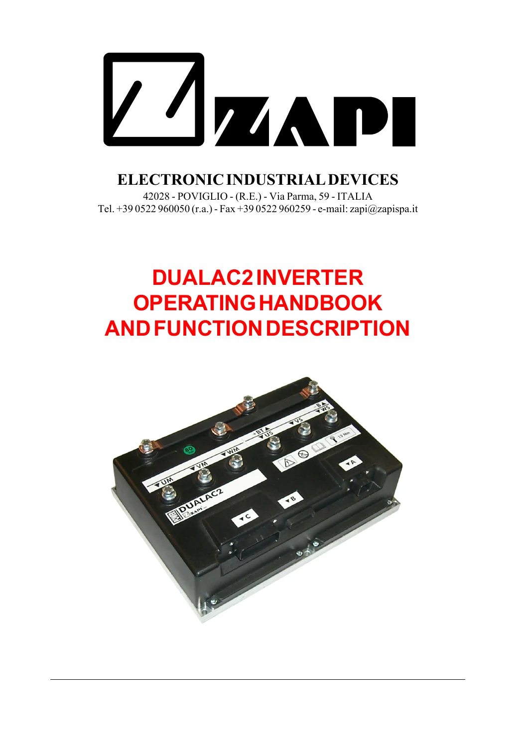
ZAPI DualAC2 / DualAC2&HP Power Inverter Operating, Programming & Diagnostic Manual – March 2003 PDF
Original price was: $32.95.$18.95Current price is: $18.95.
85-page ZAPI DualAC2, DualAC2 Power, DualAC2&HP and DualAC2&HP Power inverter technical manual, Publication AE9ZP0BA, March 2003. Includes specifications, connector pinouts, CAN-BUS and encoder wiring, standalone connection diagrams, Digital Console programming, controller setup, tester functions, alarm history, traction and pump fault codes and periodic maintenance.
Description
ZAPI DualAC2 / DualAC2&HP Power Inverter Technical Manual
The ZAPI DualAC2 / DualAC2&HP Power Inverter Operating, Programming & Diagnostic Manual – March 2003 PDF is an 85-page English technical handbook for the ZAPI DualAC2 controller family. Published as Publication No. AE9ZP0BA, March 2003 edition, it covers DualAC2, DualAC2 Power, DualAC2&HP and DualAC2&HP Power inverter configurations used in battery-powered traction and hydraulic applications.
This manual combines electrical specifications with installation information, connector pinouts, CAN-BUS configuration, encoder installation, power connections, mechanical drawings, complete standalone connection diagrams, Digital Console programming, parameter adjustment, live tester functions and detailed traction and hydraulic-pump controller diagnostics.
Controller Versions Covered
- DualAC2
- DualAC2 Power
- DualAC2&HP
- DualAC2&HP Power
The DualAC2 controller is designed to control pairs of AC asynchronous three-phase motors, while the DualAC2&HP version can additionally control a DC-series hydraulic pump motor. The manual identifies electric trucks, utility vehicles and tractors among the intended battery-powered applications.
DualAC2 Technical Specifications
The specification chapter provides separate technical data for DualAC2, DualAC2&HP, DualAC2 Power and DualAC2&HP Power variants together with controller block diagrams.
For the standard DualAC2 version, the manual lists nominal operating voltages of 24, 36, 48, 72 and 80 V. Maximum current ratings include 350 A RMS per motor at 24 V, 275 A RMS per motor at 36/48 V and 200 A RMS per motor at 72/80 V for the stated short-duration ratings. Operating frequency is 8 kHz, with an external temperature range of -30°C to +40°C and a stated maximum inverter temperature of 75°C at full power.
Input Devices and Control Signals
The manual explains the external devices required for controller operation, including microswitches, accelerator units, other analog controls, motor-speed feedback and steering-angle transducers.
Accelerator input may be provided through a potentiometer or Hall-effect device. The manual describes the CPOT, PPOT and NPOT circuits and explains automatic accelerator-signal acquisition using the PROGRAM VACC function.
Safety and Protection
Dedicated sections cover controller protection features, operational characteristics, diagnosis, thermal considerations, general precautions, electromagnetic susceptibility and emissions, main-contactor operation and emergency-switch requirements.
The controller continually performs diagnostic checks on critical functions, and the manual explains how fault information can be accessed through the Digital Console and controller alarm system.
Installation and Connector Pinouts
The installation chapter provides requirements for connection cables, contactors and fuses before moving into detailed connector descriptions.
Connector information is provided separately for DualAC2 / DualAC2 Power and DualAC2&HP / DualAC2&HP Power. Signal coverage includes CAN-BUS, Digital Console communication, encoder inputs, key supply, seat switch, forward and reverse commands, traction enable, brake input, accelerator, steering potentiometer, motor-temperature sensors, contactor outputs, auxiliary outputs and hydraulic controls.
Encoder and CAN-BUS Information
The encoder-installation section explains the connection of motor-speed feedback devices. The CAN-BUS section describes controller network configuration and built-in termination arrangements.
Separate examples cover the DualAC2 controller operating as a stand-alone module, CAN-BUS termination module and repetition module.
Power Connections and Mechanical Drawings
The manual provides separate power-connection information for DualAC2, DualAC2 Power, DualAC2&HP and DualAC2&HP Power controllers.
Mechanical drawings give controller dimensions for all four variants, helping technicians identify installation space, mounting points and controller configuration.
Complete Controller Connection Diagrams
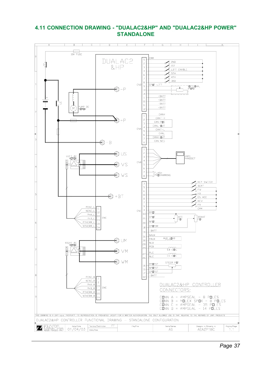
Two full standalone electrical connection drawings are included:
- DualAC2 / DualAC2 Power standalone connection drawing
- DualAC2&HP / DualAC2&HP Power standalone connection drawing
These diagrams show battery and fuse connections, traction motors, encoders, CAN-BUS, Digital Console interface, key and directional inputs, accelerator and brake circuits, steering input, contactor outputs and hydraulic-control connections where applicable.
Digital Console Programming & Adjustments
A major section of the manual covers Programming & Adjustments Using Digital Console. The Digital Console connects to the inverter’s B connector, and the manual specifies the compatible CK ULTRA EPROM requirement.
Separate menu structures are illustrated for DualAC2 and DualAC2&HP Master and Slave controllers. The diagrams show access to parameter changes, TESTER values, SAVE and RESTORE functions, alarms, PROGRAM VACC and configuration adjustments.
Function Configuration and Parameter Regulation
The configuration menus allow technicians to adjust controller options such as hour-counter behavior, battery checking, hydraulic steering operation, stop-on-ramp function and auxiliary inputs. Additional parameters cover traction characteristics, steering inputs, braking behavior, battery voltage and hydraulic functions.
DualAC2&HP configurations include additional hydraulic and pump-control parameters for applications using the integrated DC pump chopper.
Live TESTER Functions
The Digital Console TESTER function allows technicians to observe controller operating values and input states in real time. Depending on controller version, monitored data includes:
- Motor voltage
- Motor frequency
- Encoder feedback
- Slip
- Motor current
- Controller temperature
- Accelerator voltage
- Steering information
- Forward and reverse switches
- Seat and enable inputs
- Brake and handbrake status
- Battery voltage
- Battery charge
- Hour meter
- Hydraulic speed inputs
- Pump current and voltage
- Pump temperature
SAVE, RESTORE and Alarm History
The handbook describes SAVE and RESTORE functions for transferring controller parameter sets using a PC console. This allows controller configurations to be stored and later downloaded to another compatible controller.
The alarm system stores the most recent five faults together with information such as hour-meter value and controller temperature at the time of the alarm, providing useful historical information during intermittent fault diagnosis.
PROGRAM VACC Accelerator Calibration
PROGRAM VACC is used to acquire and store the useful minimum and maximum accelerator-potentiometer signal range. The manual explains this function as part of the setup and calibration process for the traction controller.
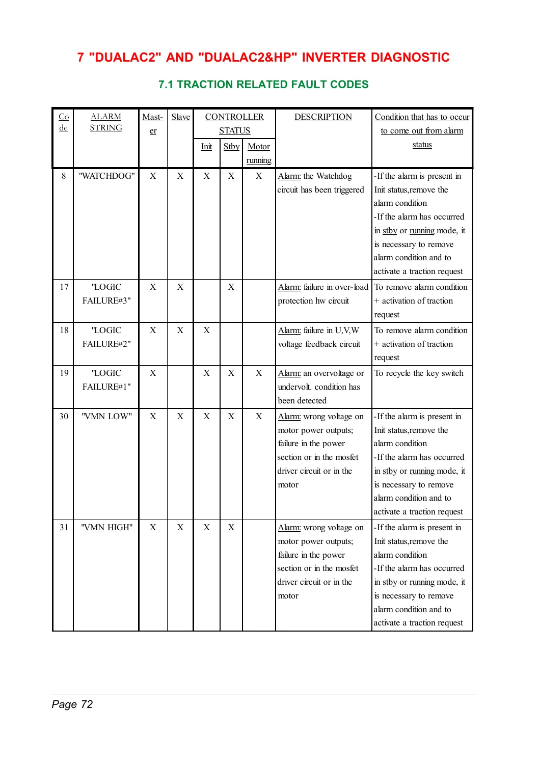
DualAC2 Traction Fault Codes
The inverter diagnostic section provides traction fault-code tables and detailed analysis. Faults covered include:
- WATCHDOG
- LOGIC FAILURE #1 / #2 / #3
- VMN LOW
- VMN HIGH
- STBY I HIGH
- CAP CHARGE
- DRIVER SHORTED
- CONTACTOR DRIVER
- COIL SHORTED
- CONTACTOR CLOSED
- CONTACTOR OPEN
- ENCODER ERROR
- STEER SENSOR KO
- PEDAL WIRE KO
- WRONG SET BATTERY
- SLAVE KO
- MASTER KO
- INPUT MISMATCH
- AUX OUTPUT KO
- EEPROM KO
- HIGH TEMPERATURE
- MOTOR TEMPERATURE
- BATTERY LOW
- VACC NOT OK
- INCORRECT START
- FORWARD + BACKWARD
- THERMIC SENSOR KO
- WAITING FOR NODE
- NO CAN MESSAGE
The alarm-analysis pages provide possible causes and diagnostic directions for motor wiring, controller power circuits, current sensors, capacitor charging, contactors, encoder signals, steering potentiometers, accelerator circuits, CAN-BUS communication and temperature-related faults.
Hydraulic Pump Controller Fault Codes
For DualAC2&HP applications, a separate diagnostic section covers hydraulic pump-chopper alarms. These include:
- PUMP VMN LOW
- PUMP STBY I HIGH
- PUMP TEMPERATURE
- PUMP controller warning
- PUMP INC. START
- PUMP VACC-related warning
Alarm analysis discusses possible faults in the pump-chopper power stage, driver section, voltage-feedback circuit, current sensor, pump motor and temperature-sensing circuitry.
Recommended Spare Parts and Maintenance
The manual includes recommended inverter spare parts such as high-current strip fuses, control-circuit fuses and contactors. The periodic-maintenance section calls for recurring checks of electrical contacts, microswitches, battery cables, controller-to-motor cables, pedal or tiller operation and contactor movement.
Several of these inspections are specified at approximately three-month intervals and are intended to be performed by qualified service personnel.
File Details
- Manual type: Operating Handbook / Programming & Diagnostic Manual
- Manufacturer: ZAPI
- Controller family: DualAC2 / DualAC2 Power / DualAC2&HP / DualAC2&HP Power
- Publication No.: AE9ZP0BA
- Edition: March 2003
- Language: English
- Pages: 85
- File format: PDF
Main Chapters Covered
- Introduction
- Specifications
- Control Units and Input Devices
- Protection Features
- Operational Features
- Diagnosis
- Thermal Considerations
- Safety and Protection
- Installation
- Connector Descriptions
- Encoder Installation
- CAN-BUS Configuration
- Power Connections
- Mechanical Drawings
- Standalone Connection Drawings
- Programming & Adjustments Using Digital Console
- Function Configuration
- Parameter Regulation
- Programming Console Functions
- AC Inverter Traction Setup
- TESTER Functions
- SAVE and RESTORE
- Alarm Menu
- PROGRAM VACC
- DualAC2 and DualAC2&HP Inverter Diagnostics
- Traction Fault Codes
- Pump Fault Codes
- Recommended Spare Parts
- Periodic Maintenance
The ZAPI DualAC2 / DualAC2&HP Power Inverter Operating, Programming & Diagnostic Manual provides a complete reference for technicians working with this earlier controller generation. Its combination of connection diagrams, connector pinouts, Digital Console programming, live tester information and detailed fault-code analysis makes it useful for controller installation, configuration and troubleshooting.
IMAGES PREVIEW
Download the ZAPI DualAC2 March 2003 Manual
This March 2003 edition is useful when servicing equipment fitted with earlier DualAC2-family controller hardware or software where the corresponding AE9ZP0BA documentation is required. The manual is supplied as an instant PDF download after purchase, with no physical shipping required, and can be viewed digitally or printed for workshop use.
Reviews
There are no reviews yet.