Description
File Details
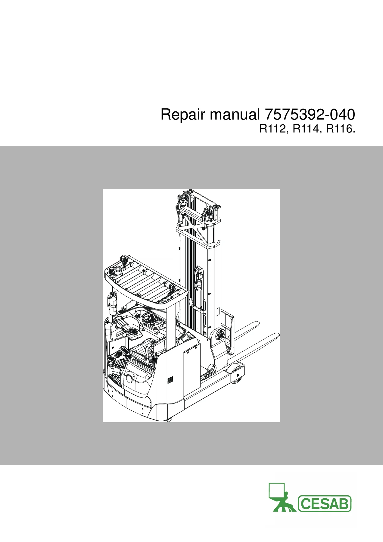
- Manual Type: Repair Manual / Workshop Service Manual
- Brand: Cesab
- Models Covered: R112, R114, R116
- Language: English
- Page Count: 538 pages
- File Format: PDF
- Document Number: 7575392-040
- Revision Date: 2016-10-24
- Applies from Serial Number: 6308581
- T-Code: 1006
Chapters Covered
This Cesab R112 R114 R116 repair manual is organized into twenty comprehensive chapters covering every major system and component of these reach trucks:
- General Introduction β How to use this manual, abbreviations, warning symbols, pictograms for screws/nuts and repairable units
- General Safety Rules β Work safety, electrical system safety, safe lifting procedures, truck modification guidelines
- Operation and Connection Sequences β Detailed event tables for login procedures, driving in fork and drive wheel directions, braking, reach carriage operation, steering, fork lifting/lowering, fork tilt, sideshift, and emergency lowering
- Parameters β Complete parameter reference including operator parameters (1-100), service parameters (101-999), factory parameters (1001-1250), and calibration parameters (1251-1500)
- Installation β Transporting the truck and mast, taking into operation, battery placement, dismantling the mast, installing the mast in the truck, fitting the working light
- Maintenance β Safety precautions, cleaning instructions, crack detection using liquid penetrant and magnetic yoke methods, safety checks, and detailed periodic maintenance schedules for 500, 1000, 2000, 3000, 4000, and 5000 operating hours
- Troubleshooting β Error log menu, error information menu, CID diagnostic screens, initial troubleshooting flowcharts, troubleshooting using blocking symbols, troubleshooting using error codes, and troubleshooting without indications
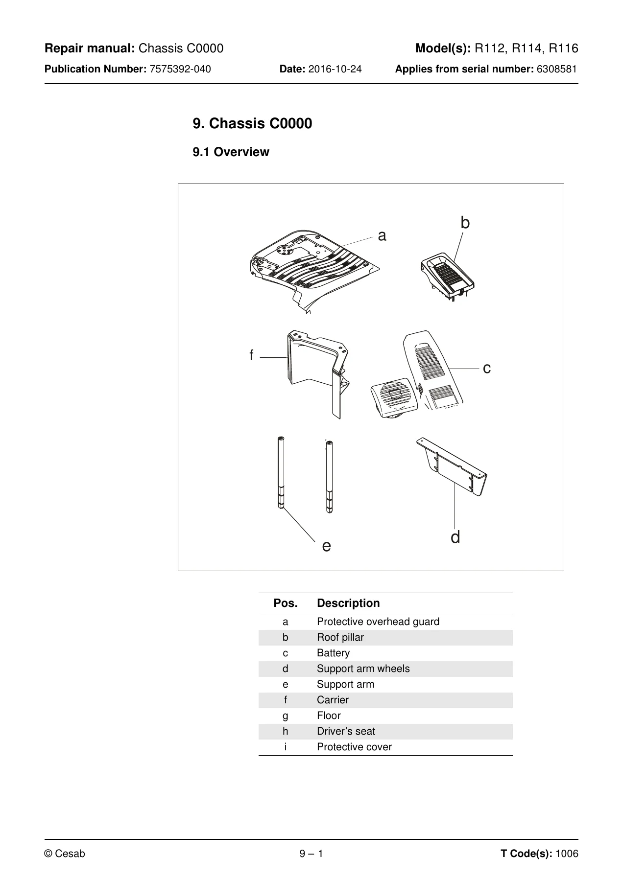
- Chassis C0000 β Floor replacement, protective covers, support arm, battery compartment parts, operator’s seat (Basic, Comfort Low, Comfort High), seat switch, backrest, seat plate, operator controls, accelerator/brake pedal, safety pedal, overhead guard/roof, finger-foot guard
- Motors C1000 β Electric pump motor (removal, installation, temperature sensor replacement), steering motor (steering servo motor replacement), electric fan motor/fan (frequency converter fan and motor compartment fan), electric drive motor (replacement, temperature sensor, RPM sensor)
- Mechanical Drive Gear Unit C2000 β Checking oil level, oil change, leakage from lower cover, replacing the drive gear, replacing steering bearings
- Brake System/Wheels C3000 β Brake system overview, drive motor brake (travel brake), parking brake (replacement, dust plug, hub, rubber gaiter, brake force check, air gap check), wheels, drive wheel replacement, support arm wheel replacement, bearing replacement, wheel bolt replacement
- Steering System C4000 β Electric steering wheel, pulse transducer replacement, steering console replacement, wiring harness replacement, steering wheel replacement, steering unit, steering reference sensor replacement
- Electrical System C5000 β OTP, battery (recommendations, charging, BDI algorithm, cable replacement), signal/alarm, main contactor, instrument panel, operating controls, CID, height indication, travel function wiring/fuse, drive motor cables/resistor/fuse, transistor panel (ACT and ACH replacement), work function harnesses/fuse, main processor MCU, sending units and sensors, safety sensors, height measurement system, calibration procedures
- Hydraulic System C6000 β Hydraulic hygiene, bleeding the system, hose inspection, hydraulic couplings, hydraulic oil tank, hydraulic hoses, filter, hydraulic pump, main valve unit, control valve, chassis-mounted hydraulic hoses, mast hydraulic conduits, main lift cylinder, free lift cylinder, reach/telescopic cylinder, tilting cylinder, sideshift cylinder
- Mast C7000 β Main mast, main lifting chain system (inspection, lubrication, free lift chain replacement, mast chain replacement, mast harness replacement), fork carriage (wear strip check, lubrication, fork yoke replacement), main mast suspension, forks (inspection, repairs, testing)
- Wiring Diagram β Component list, component location, connections for ACT, ACH, CID, MCU, fuse panel, steering motor, general wiring diagram, detailed diagrams
- Hydraulics Schematics β Component list, component location, main valve unit, fork carriage valve, hydraulic schematics
- Tools β AMP connectors, MQS contacts, CPC contacts, other special tools
- Service Data and Grease Specifications β General tightening torques for galvanised and untreated screws, oil and grease specifications
- Technical Data β Mast type and weight, IP classes, battery sizes, truck dimensions, lift height dependent dimensions
This Cesab R112 R114 R116 repair manual delivers the complete workshop-level documentation needed to service, maintain, and repair these reach trucks. Covering everything from the chassis and drive gear to the electrical and hydraulic systems, the manual provides detailed procedures, exploded views, wiring diagrams, and hydraulic schematics that guide technicians through every major repair and adjustment. The troubleshooting chapter alone spans dozens of pages of error codes, diagnostic screens, and systematic fault-finding steps that help isolate problems quickly and accurately.
What This Manual Enables You To Do
Whether you are a fleet maintenance technician, an independent workshop, or an operator maintaining your own equipment, this Cesab R112 R114 R116 repair manual gives you the exact procedures and specifications to:
- Diagnose and repair electrical faults using the MCU error code system and CID diagnostic screens
- Rebuild hydraulic cylinders β main lift, free lift, reach, tilt, and sideshift
- Replace and adjust parking brakes, drive wheels, and support arm wheels
- Service the drive gear, check oil levels, and replace steering bearings
- Replace the drive motor, pump motor, and steering servo motor
- Remove and install the mast, including chain replacement and adjustment
- Calibrate the joystick, height measurement system, and lowering valve
- Perform periodic maintenance from 500-hour to 5000-hour intervals
- Interpret wiring diagrams and hydraulic schematics for fault tracing
- Set and adjust truck parameters for performance and safety
Why This Manual Matters
Reach truck repairs without the correct specifications can lead to premature component failure, unsafe operating conditions, and costly downtime. This manual provides the manufacturer’s exact torque values, pressure settings, calibration procedures, and service limits. The step-by-step instructions include safety warnings and tool requirements, helping you complete repairs correctly the first time. From the 250 A main fuse to the 41 Nm nominal parking brake torque, every critical specification is documented.
Complete PDF Bookmark Tree
Complete Bookmarks
The complete bookmarks in the βCesab R112 R114 R116 Reach Truck Repair Manual – Complete Workshop Service PDFβ are as follows:
1. Table of contentp. 3
+2. General introductionp. 11
2.1 How to use this manualp. 11
2.2 Abbreviationsp. 12
2.3 Warning symbolsp. 13
+2.4 Pictogramsp. 14
+2.4.1 Screws/Nutsp. 14
Identification of tools for screws and nutsp. 14
2.4.2 Repairablep. 15
2.4.3 Other pictogramsp. 16
+3. General safety rulesp. 19
3.1 Work safetyp. 19
3.2 Electrical systemp. 21
3.3 Safe liftingp. 22
3.4 Truck modificationsp. 23
+4. Operation and connection sequencesp. 25
+5. Parametersp. 35
5.1 Generalp. 35
+5.2 Parameter settingsp. 36
Accessp. 37
Parameter screensp. 37
+5.3 Operator parametersp. 38
+5.3.1 Overviewp. 39
Connection to logged-in operatorp. 39
+5.3.2 Descriptionp. 42
Parameter 2, 3 β Maximum travel speedp. 42
Parameters 4 and 5 β Acceleration/Decelerationp. 42
+5.4 Service parametersp. 43
5.4.1 Overviewp. 43
+5.4.2 Descriptionp. 43
Parameter 101/104 β Service/Log-outp. 43
Parameter 107/108 β Batteryp. 44
Parameter 105/106/114/115/117 (Travel alarms 1 and 2)p. 47
Parameters 109/110/111/112/117 β Collision sensorp. 49
Parameter 201 β Retardation when reversingp. 51
Parameter 202/203/204 β Adjusting erroneous, maximum travel speedsp. 51
Parameter 208 – Creep speed in travel direction controlp. 51
Parameter 213 β Permanently reduced maximum travel speedp. 52
Parameter 214 β Adjusting the maximum travel speed in main lift rangep. 53
Parameters 215/216p. 53
+5.4.3 Descriptionp. 55
Parameters 301/302 β Extra valve functionp. 55
Parameters 305/306 β Maximum oil pressure through valve Q18p. 56
Parameters 309/310 β Maximum oil pressure through valve Q19p. 57
Parameters 313/314 β Closing timep. 57
Parameters 317/318 β Maximum oil flow through valve Q18p. 57
Parameters 321/322 β Maximum oil flow through valve Q19p. 58
Parameters 325/326 β Opening/closing time valve Q19p. 58
Parameters 329/330 β Opening/closing time valve Q19p. 58
Parameter 341/342 β Reducing the lifting/lowering speedp. 59
Parameter 343 β Reduction of reach speedp. 59
Parameter 345- Lift/lower sensitivityp. 59
Parameters 346/347 β Ramping speedsp. 59
Parameters 371/373/375/378 β Height limitationp. 60
Parameter 380 β Lift height limitsp. 62
Parameter 387 β Configuring the lift height limitationsp. 62
Parameter 503 β Login methodp. 63
Parameter 508/509/512/513 β CID configurationp. 64
+5.5 Factory parametersp. 65
+5.5.1 General factory parametersp. 65
Overviewp. 65
Descriptionp. 66
Parameter 1001 – Truck typep. 66
Parameter 1002 β Mast typep. 66
Parameter 1003 β Hydraulic pumpp. 66
Parameter 1007 β Activation of hydraulic leversp. 67
Parameter 1009 β Height indicationp. 67
+5.5.2 Factory parameters, activation of optionsp. 68
Overviewp. 69
Descriptionp. 69
+5.5.3 Factory parameters, calibrationp. 70
+6. Installationp. 73
6.1 Transporting the truckp. 73
6.2 Transporting the mastp. 73
+6.3 Transporting the truckp. 73
Method 1p. 73
Method 2p. 74
+6.4 Taking into operationp. 74
+6.5 Dismantling the mastp. 76
6.5.1 Dismantling the working light.p. 80
+6.6 Putting into operation.p. 81
6.6.1 Installing the mast in the truck.p. 81
6.6.2 Fitting the working light.p. 87
+7. Maintenancep. 89
7.1 Introductionp. 89
7.2 Safety precautions for maintenance workp. 90
+7.3 Maintenance instructionsp. 91
7.3.1 Cleaning and washingp. 91
7.3.2 High-pressure washersp. 91
7.3.3 Degreasing agentsp. 91
7.3.4 Cleaning the exteriorp. 92
7.3.5 Cleaning the chainp. 92
7.3.6 Cleaning the motor compartmentp. 92
7.3.7 Electric componentsp. 92
7.4 Symbolsp. 93
+7.5 CCrack detectionp. 94
7.5.1 Visual inspectionp. 94
+7.5.2 Crack detectionp. 95
Crack detection with liquid penetrantp. 95
Crack detection with magnetic yokep. 95
7.6 Safety checksp. 96
+7.7 Periodic maintenancep. 97
7.7.1 Every 500 operating hours/180 daysp. 97
7.7.2 Every 1000 operating hours/360 daysp. 99
7.7.3 Every 2000 operating hours/720 daysp. 105
7.7.4 Every 3000 operating hours/1080 daysp. 107
7.7.5 Every 4000 operating hours/1440 daysp. 109
7.7.6p. 109
7.7.7 Every 5000 operating hours/1800 daysp. 109
7.7.8 Annual status inspectionp. 109
+8. Troubleshootingp. 111
+8.1 Auxiliary functionsp. 111
+8.1.1 Error log menup. 111
Descriptionp. 111
Accessp. 111
+8.1.2 Error information menup. 112
Descriptionp. 112
Accessp. 112
+8.1.3 Diagnostic screensp. 112
Descriptionp. 112
Accessp. 112
Screen 1 β CID analogue inputsp. 113
Screen 2 β CID digital inputsp. 114
Screen 3 β MCU analogue inputsp. 115
Screen 4 β MCU digital inputsp. 116
Screen 5 β MCU digital outputsp. 117
Screen 6 β Pulse-width modulated outputsp. 118
Screen 11 β Temperaturesp. 119
Screen 12 β Voltagesp. 119
Screen 13 β travel functionp. 120
Screen 14 β Steering functionp. 121
Screen 15 β Displays information about lifting/loweringp. 122
Screen 16 β Displays reach in and reach out information.p. 123
Screen 17 β Displays tilt and sideshift information.p. 124
8.2 Initial troubleshootingp. 125
8.3 Troubleshooting using blocking symbolp. 126
+8.4 Troubleshooting using error codesp. 130
8.4.2 MCU and other warnings and errorsp. 135
+8.5 Troubleshooting without indicationsp. 173
8.5.1 Mechanical brake (3000)p. 173
8.5.2 Steering (4000)p. 174
+9. Chassis C0000p. 175
9.1 Overviewp. 175
9.2 Descriptionp. 176
+9.3 Floor C0330p. 176
9.3.1 Overviewp. 176
9.3.2 Descriptionp. 177
+9.3.3 Replacing the floorp. 177
Removing the floorp. 177
Adjusting the floorp. 178
Fitting the floorp. 179
+9.3.4 Protective coversp. 180
Overviewp. 180
Descriptionp. 181
Replacing the top coverp. 181
Removing the top coverp. 181
Fitting the top coverp. 182
Replacing the steering arm coversp. 183
Removing the steering arm coversp. 183
Fitting the steering arm coversp. 183
Replacing the cover, wiring harnessp. 184
Removing the cover, wiring harnessp. 184
Fitting the cover, wiring harnessp. 184
Replacing the elbow panelp. 185
Removing the elbow panelp. 185
Replacing the motor coverp. 186
Removing the motor coverp. 186
Fitting the motor coverp. 187
Replacing the inner motor coverp. 188
Removing the inner motor coverp. 188
Fitting the inner motor coverp. 188
Replacing the front knee coverp. 189
Removing the front knee coverp. 189
Fitting the front knee coverp. 189
9.4 Support arm C0350p. 190
+9.5 Battery compartment parts C0390p. 190
9.5.1 Overview, battery supportp. 190
+9.6 Operator's seat C0620p. 191
9.6.1 Overviewp. 191
9.6.2 Descriptionp. 191
+9.6.3 Replacing the operatorβs seat (Basic)p. 192
Removing the operatorβs seat (Basic)p. 192
Fitting the operatorβs seat (Basic)p. 193
Adjusting the operatorβs seat (Basic)p. 194
Removing the operatorβs seat (Comfort Low, Comfort High)p. 195
Fitting the operatorβs seat (Comfort Low, Comfort High)p. 196
Adjusting the operatorβs seat (Comfort Low, Comfort High)p. 197
+9.6.4 Seat switchp. 198
Replacing the seat switch (Comfort)p. 198
Removing the seat switch (Comfort)p. 198
Removing the seat switch (Comfortt)p. 199
+9.6.5 Replacing the backrest, chair seatp. 200
Removing the backrest (Comfort Low, Comfort High)p. 200
Fitting the backrest (Comfort Low, Comfort High)p. 201
Removing the seat padp. 202
Fitting the seat padp. 202
+9.6.6 Replacing the seat platep. 203
Removing the seat platep. 203
Fitting the seat platep. 204
+9.7 Operator controls C0640p. 205
9.7.1 Overviewp. 205
9.7.2 Descriptionp. 205
9.7.3 Preconditionsp. 205
+9.7.4 Accelerator/Brake pedalp. 206
Replacing the accelerator/brake pedalp. 206
Removing the accelerator/brake pedalp. 206
Fitting the accelerator/brake pedalp. 207
+9.7.5 Safety pedalp. 207
Replacing the safety pedalp. 207
Removing the safety pedalp. 208
Fitting the safety pedalp. 208
9.8 Interior fittings C0680p. 209
9.9 Mirrors C0740p. 209
+9.10 Overhead guard/Roof C0810p. 209
9.10.1 Overviewp. 209
9.10.2 Descriptionp. 210
+9.10.3 Replacing the overhead guard roofp. 210
Removing the overhead guard roofp. 210
Fitting the overhead guard roofp. 211
+9.10.4 Replacing the front roof supportp. 212
Remove the overhead guard roofp. 212
Removing the front roof supportp. 212
Fitting the front supportp. 213
+9.10.5 Replacing the rear roof supportp. 214
Removing the rear roof supportp. 214
Fitting the rear supportp. 214
+9.11 Finger-foot guard C0820p. 215
Replacing a finger guardp. 215
Removing the finger guardp. 215
Fitting the finger guardp. 216
+10. Motors C1000p. 219
10.1 Overviewp. 219
10.2 Descriptionp. 219
+10.3 Electric pump motor C1710p. 220
10.3.1 Overviewp. 220
10.3.2 Descriptionp. 221
+10.3.3 Replacing the pump motorp. 222
Removing the pump motorp. 223
Methodp. 224
Fitting the pump motorp. 225
+10.3.4 Replacing the temperature sensorp. 227
Removing the temperature sensorp. 227
Installing the external temperature sensorp. 228
Methodp. 228
+10.4 Steering motor C1730p. 229
10.4.1 Overviewp. 229
10.4.2 Descriptionp. 230
10.4.3 Layout of the flange holesp. 232
+10.4.4 Steering servo motor replacementp. 233
Removing the steering servo motorp. 233
Fitting the steering servo motorp. 234
Lubrication of the steering servo motor ring gearp. 235
+10.5 Electric fan motor / fanp. 236
+10.5.1 Fan for frequency converterp. 236
Overviewp. 236
Descriptionp. 236
+10.5.2 Replacing the frequency converter fanp. 237
Removing the frequency converter fan.p. 237
Fitting the frequency converter fanp. 238
+10.5.3 Motor compartment fanp. 239
Overviewp. 239
Descriptionp. 239
+10.5.4 Replacing the motor compartment fanp. 240
Removing the motor compartment fan.p. 240
Fitting the motor compartment fanp. 241
+10.6 Electric drive motor C1760p. 242
10.6.1 Overviewp. 242
10.6.2 Descriptionp. 243
+10.6.3 Replacing the drive motorp. 244
Removing the drive motorp. 244
Fitting the drive motorp. 245
Methodp. 245
+10.6.4 Replacing the temperature sensorp. 246
Removing the temperature sensorp. 246
Installing the external temperature sensorp. 247
+10.6.5 Replacing the RPM-sensor.p. 248
Removing the RPM-sensorp. 248
Fitting the RPM-sensorp. 249
+11. Mechanical Drive Gear Unit C2000p. 251
11.1 Overviewp. 251
11.2 Descriptionp. 252
11.3 Checking the oil levelp. 253
11.4 Oil changep. 255
11.5 Leakage from the lower coverp. 257
+11.6 Replacing the drive gearp. 258
11.6.1 Removing the drive gearp. 258
11.6.2 Fitting the drive gearp. 260
+11.7 Replacing the Steering bearingsp. 261
Removing the steering bearingsp. 261
Fitting the steering bearingp. 261
+12. Brake system/Wheels C3000p. 263
+12.1 Brake system C3100p. 263
12.1.1 Overviewp. 263
+12.1.2 Descriptionp. 264
Travel brakep. 264
Emergency brakep. 264
+12.1.3 Drive motor brake (travel brake)p. 265
Accelerator releasedp. 265
Changing the direction of travelp. 265
+12.2 Parking brake C3370p. 266
12.2.1 Overviewp. 266
12.2.2 Descriptionp. 267
+12.2.3 Replacing the parking brakep. 268
Removing the parking brakep. 268
Fitting the parking brakep. 269
+12.2.4 Replacing the dust plugp. 270
Removing the dust plugp. 270
Fitting the dust plugp. 271
+12.2.5 Replacing the hubp. 272
Removing the hubp. 272
Fitting the hubp. 273
+12.2.6 Replacing the rubber gaiterp. 274
Fitting the rubber gaiterp. 275
+12.2.7 Checking the parking brake's brake forcep. 276
Checking the parking brake's brake forcep. 276
12.2.8 Checking the parking brake air gapp. 277
+12.3 Wheels C3500p. 278
12.3.1 Descriptionp. 278
12.3.2 Wheel wearp. 279
+12.4 Drive wheel C3530p. 279
12.4.1 Overviewp. 279
+12.4.2 Replacing the drive wheelp. 280
Removing the drive wheelp. 280
Fitting the drive wheelp. 282
+12.5 Support arm wheel C3550p. 283
12.5.1 Overviewp. 283
+12.5.2 Replacing an unbraked support arm wheelp. 284
Removal of an unbraked support arm wheelp. 284
Methodp. 284
Fitting of an unbraked support arm wheelp. 285
Methodp. 285
+12.5.3 Replacing bearingsp. 286
Removing the bearingsp. 286
Assembling bearingsp. 287
12.5.4 Replacing the wheel boltp. 288
+13. Steering system C4000p. 289
13.1 Descriptionp. 289
+13.2 Electric steering wheel C4310p. 290
13.2.1 Overviewp. 290
13.2.2 Descriptionp. 290
13.2.3 Adjustmentp. 291
13.2.4 Replacing pulse transducer [B13]p. 292
+13.2.5 Replacing the steering consolep. 293
Removing the steering consolep. 293
Methodp. 293
13.2.6 Replacing the wiring harness in the steering consolep. 295
13.2.7 Fit the steering console in the truckp. 297
13.2.8 Replacing the steering wheelp. 297
+13.3 Steering unit C4330p. 298
+13.4 Steering reference sensor (4350)p. 298
13.4.1 Replacing the reference sensor [B17]p. 299
+14. Electrical system C5000p. 301
14.1 Descriptionp. 301
+14.2 OTPp. 301
Descriptionp. 301
Travel speed reduction – steering anglep. 301
+14.3 Battery C5110p. 301
14.3.1 Battery recommendationsp. 301
14.3.2 Measuring discharge currentp. 301
14.3.3 Measuring voltagep. 301
14.3.4 Charging the batteryp. 301
14.3.5 BDI algorithm and parameter settingp. 303
14.3.6 Performance limitations due to battery statusp. 303
14.3.7 Performance limitations due to battery status and parameter settingp. 303
14.3.8 CID symbolp. 303
14.3.9 Resetting the battery indicator (BDI)p. 303
14.3.10 Battery weightp. 303
14.3.11 Parameter overview, batteryp. 304
+14.3.12 Battery cable harnessp. 304
+14.3.13 Battery cable replacement, machine partp. 305
Methodp. 305
Dismantlingp. 305
Assemblyp. 305
+14.3.14 Battery cable replacement, battery partp. 306
Methodp. 306
Dismantlingp. 306
Assemblyp. 306
+14.4 Signal / Alarm (Sound-light) C5160p. 307
+14.4.1 Hornp. 307
Overviewp. 307
Descriptionp. 307
+14.4.2 Replacing the hornp. 308
Methodp. 308
Dismantlingp. 308
Assemblyp. 308
+14.5 Main contactor C5190p. 309
Overviewp. 309
Descriptionp. 309
+14.5.1 Replacing the contactorp. 309
Methodp. 309
Dismantlingp. 309
Assemblyp. 309
+14.6 Instrument panel C5200p. 310
Descriptionp. 310
14.6.1 Operating controlsp. 311
+14.6.2 Replacing the operating controlsp. 311
Dismantlingp. 311
Assemblyp. 312
14.6.3 Replacing the switch for travel direction selection / hornp. 313
14.6.4 Replacing the controls on the operating panelp. 313
+14.6.5 Central Information Display (CID)p. 313
Menu navigationp. 318
LED symbolsp. 321
+14.6.6 Replacing the CIDp. 322
Overviewp. 322
Methodp. 322
Dismantlingp. 322
+14.7 Height indicationp. 323
Overviewp. 323
Descriptionp. 324
+14.7.1 Replacing the sensor bearingp. 324
Methodp. 324
Dismantlingp. 324
Assemblyp. 324
+14.7.2 Replacing the height reference sensorp. 324
Methodp. 324
Dismantlingp. 324
Assemblyp. 324
14.7.3 Hight indication wirep. 325
14.7.4 Check and adjust the wirep. 326
+14.7.5 Replacing the height indication wiringp. 326
Methodp. 326
Dismantlingp. 326
Assemblyp. 326
+14.8 Travel function wiring/ fuse C5390p. 327
+14.8.1 Chassis wiringp. 327
Removing the chassis wiringp. 327
+14.8.2 Operator control wiringp. 328
Methodp. 328
Dismantlingp. 328
+14.9 Drive motor cables/resistor/fuse C5430p. 328
14.9.1 Replacing motor cablesp. 328
+14.10 Transistor panel C5460p. 329
Overviewp. 329
Descriptionp. 329
+14.10.1 Replacing the ACTp. 331
Removing the covers.p. 331
Methodp. 331
Fitting the ACT.p. 332
Methodp. 332
Software updatep. 332
Checking the ACTp. 332
Fitting the floorp. 332
Fit the coversp. 333
+14.10.2 Replacing ACH.p. 333
Removing the floorp. 333
Removing the coversp. 333
Methodp. 333
Fitting the ACH.p. 334
Methodp. 334
Software update.p. 334
Checking the ACHp. 335
Fitting the floorp. 335
Fit the coversp. 335
+14.11 Work function harnesses / fuse C5590p. 335
+14.11.1 Fuse panelp. 335
Overviewp. 335
Descriptionp. 336
+14.11.2 Checking fusesp. 336
+14.11.3 Roof wiringp. 337
Descriptionp. 337
Overviewp. 337
14.11.4 Replacing the roof wiringp. 337
+14.11.5 Mast wiringp. 337
Descriptionp. 337
Overviewp. 338
+14.11.6 Replacing the mast harnessp. 338
Methodp. 338
Dismantlingp. 338
Assemblyp. 339
+14.11.7 Check and adjust the mast wiringp. 340
Descriptionp. 340
Overviewp. 340
+14.11.8 Reach carriage wiringp. 341
Descriptionp. 341
Overviewp. 341
Replacing the reach carriage wiring harnessp. 341
Methodp. 341
Dismantlingp. 341
Assemblyp. 341
+14.12 Main processor β MCU C5710p. 342
+14.12.1 Replacing the MCUp. 346
Replacing the MCUp. 346
Removing the floorp. 346
Removing the MCUp. 346
Methodp. 346
Fitting the MCUp. 347
Methodp. 347
Fitting the floorp. 347
+14.13 Sending units and sensors C5800p. 348
14.13.1 Inductive sensorsp. 348
+14.13.2 Position sensorp. 348
Steering reference sensorp. 349
14.13.3 Pressure sensorp. 350
+14.13.4 Pulse transducerp. 350
+14.14 Safety sensor / – sensors C5830p. 352
14.14.1 Emergency switch offp. 352
+14.14.2 Emergency switch off [S21]p. 352
Descriptionp. 352
Overviewp. 352
Indications in CIDp. 352
Replacing the emergency switch offp. 353
Methodp. 353
Dismantlingp. 353
Assemblyp. 353
+14.14.3 Safety pedal [B31]p. 354
Descriptionp. 354
Locationp. 354
Indication in CIDp. 355
Replacing the safety pedalp. 356
+14.15 Height measurement systemp. 358
Descriptionp. 358
Monitoringp. 358
+14.16 Calibrationp. 359
14.16.1 Calibration of the joystickp. 359
14.16.2 Height measurement/reach movement length calibrationp. 360
14.16.3 Reference sensor, main lift. (Screen 1)p. 360
14.16.4 Pulse length for main lift sensor bearing (Screen 2)p. 361
14.16.5 Max. lift height. (Screen 3)p. 361
14.16.6 Calibration of the reach carriage extensionp. 361
14.16.7 Valve calibrationp. 362
14.16.8 Lowering valve, starting value. (Screen 1-S)p. 362
14.16.9 Lowering valve, final value. (Screen 1-E)p. 362
14.16.10 Lifting height limiting.p. 363
+15. Hydraulic system C6000p. 365
15.1 Generalp. 365
+15.2 Hydraulic hygienep. 365
15.2.1 Washingp. 365
15.2.2 Packagingp. 366
15.2.3 Handlingp. 366
15.2.4 Storagep. 366
15.2.5 Work proceduresp. 366
15.3 Bleeding the air from the hydraulic systemp. 367
15.4 Hose inspectionp. 367
+15.5 Hydraulic couplings C6230p. 367
Overviewp. 367
+15.5.1 Quick change connectorsp. 368
Assembling the quick change connectorp. 368
Disassembly of the quick change connectorp. 369
+15.5.2 Tightening torques for hydraulic connectionsp. 370
Tapered coupling with O-ringp. 370
Tredo sealp. 370
Pipe couplingp. 371
+15.6 Hydraulic unit C6100p. 373
+15.6.1 Hydraulic oil tank C6110p. 373
Descriptionp. 373
Checking the oil levelp. 373
Filling the tankp. 374
Replacing the tankp. 375
Removing the tankp. 375
Fitting the tankp. 376
+15.6.2 Hydraulic hoses C6120p. 377
Replacing the suction hosep. 377
Methodp. 377
+15.6.3 Filter C6130p. 378
Overviewp. 378
Descriptionp. 378
Filter replacement (for air and oil)p. 379
Methodp. 379
+15.7 Hydraulic pump C6140p. 380
Descriptionp. 380
15.7.1 Replacing the hydraulic pumpp. 381
+15.7.2 Replacing the driverp. 382
Disassemblyp. 382
Assemblyp. 382
Replacing O-ringsp. 383
Disassemblyp. 383
Assemblyp. 383
+15.8 Main valve unit C6210p. 384
Descriptionp. 384
Overviewp. 385
+15.8.1 Definitionsp. 386
Inserts for quick change connectorsp. 386
Tightening torques for valve componentsp. 388
Lift functionp. 388
Overviewp. 388
Descriptionp. 388
Lowering functionp. 389
Overviewp. 389
Descriptionp. 389
Reach functionp. 389
Pressure limitationp. 389
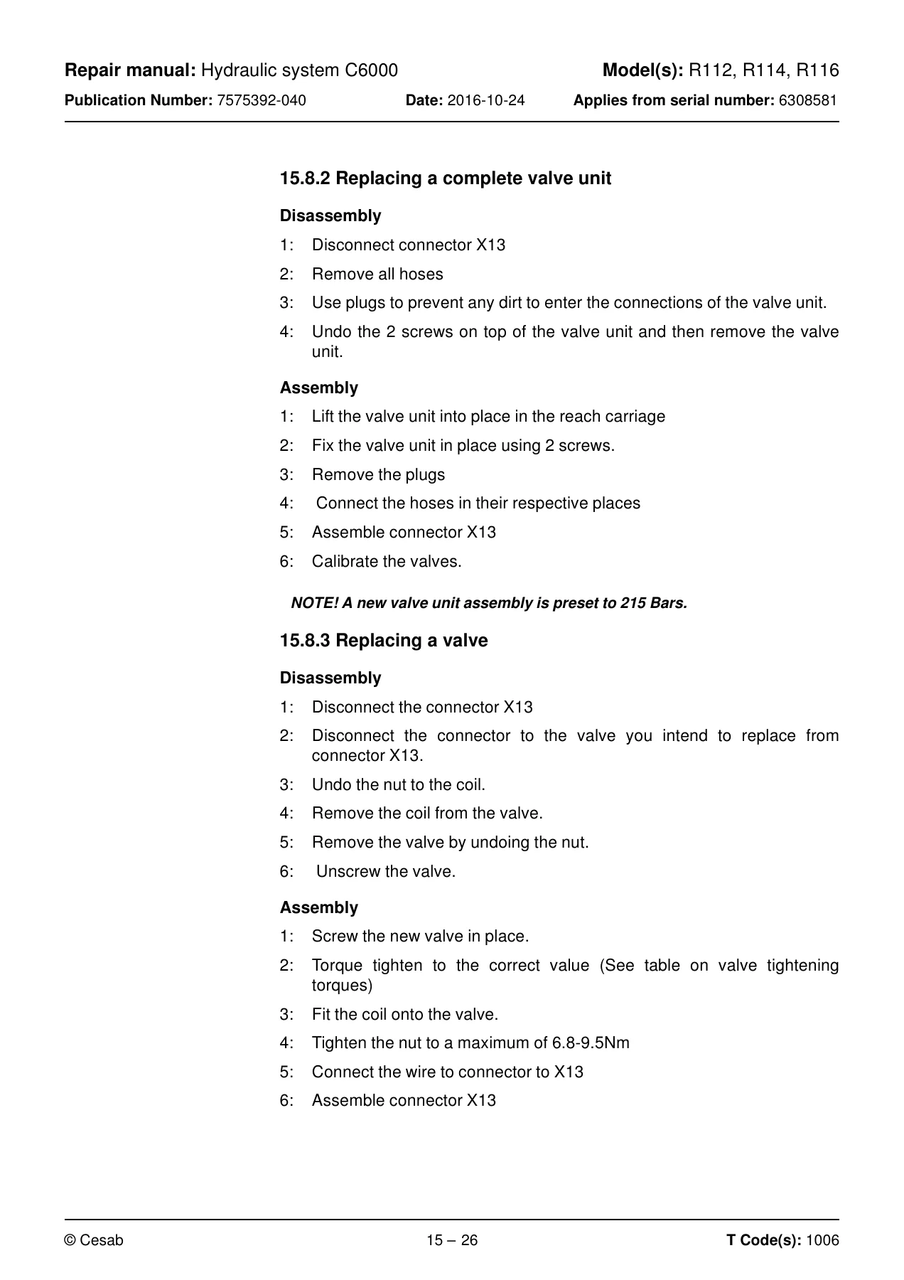
+15.8.2 Replacing a complete valve unitp. 390
Disassemblyp. 390
Assemblyp. 390
+15.8.3 Replacing a valvep. 390
Disassemblyp. 390
Assemblyp. 390
Lowering valvep. 391
Descriptionp. 391
Replacing the lowering valvep. 391
Adjusting the lowering valvep. 392
Calibrating the lowering valvep. 392
Replacing the pressure limiting valvep. 394
Overviewp. 394
Disassembly:p. 394
Assemblyp. 394
Adjustmentp. 394
Adjustment tablep. 395
+15.9 Control valve C6220p. 396
Descriptionp. 396
Overviewp. 396
Tilt functionp. 396
Overviewp. 396
Sideshift functionp. 397
+15.10 Chassis-mounted hydraulic hoses C6230p. 398
+15.10.1 Replacing the supply hosep. 398
Overviewp. 398
Disassemblyp. 398
Assemblyp. 398
+15.10.2 Replacing the return hosep. 398
Overviewp. 398
Disassemblyp. 398
Assemblyp. 398
+15.11 Mast hydraulic conduits C6320p. 399
Replacing the supply hose to the free lift cylinderp. 399
Overviewp. 399
Disassemblyp. 399
Assemblyp. 399
+15.11.1 Fork carriagep. 400
Overviewp. 400
Replacing the hose to the sideshiftp. 401
Disassemblyp. 401
Assemblyp. 401
Replacing the pipe in the fork carriagep. 402
Disassemblyp. 402
Assemblyp. 402
+15.12 Main lift cylinder C6610p. 403
Overviewp. 403
Cylinder nomenclaturep. 403
Nomenclature for cylinder headp. 404
Nomenclature for pistonp. 404
15.12.1 Removing the air cylinder from the mastp. 405
15.12.2 Replacing the hose rupture valvep. 406
+15.12.3 Dismantling the cylinderp. 407
+15.12.4 Dismantling the piston.p. 408
15.12.5 Dismantling the cylinder headp. 409
+15.12.6 Fitting the cylinder head seals.p. 411
+15.12.7 Fitting the piston guide beltp. 412
+15.12.8 Assembling the cylinderp. 413
15.12.9 Assembling a mast cylinderp. 415
+15.13 Free lift cylinder C6620p. 417
Cylinder nomenclaturep. 417
Nomenclature for cylinder headp. 418
Nomenclature for pistonp. 418
15.13.1 Removing the free lift cylinder from the truckp. 419
15.13.2 Replacing the hose rupture valve, free lift cylinderp. 419
+15.13.3 Dismantling the cylinderp. 420
+15.13.4 Dismantling the pistonp. 421
+15.13.5 Dismantling the cylinder headp. 422
+15.13.6 Fitting the cylinder head seals.p. 423
+15.13.7 Fitting the piston sealsp. 425
+15.13.8 Assembling the cylinderp. 427
15.13.9 Assembling the free lift cylinder in the mastp. 428
+15.14 Reach/telescopic cylinder C6650p. 429
Overviewp. 429
Cylinder nomenclaturep. 430
Nomenclature for cylinder headp. 431
Nomenclature for pistonp. 431
15.14.1 Removing the reach cylinder from the truckp. 432
+15.15 Dismantling the cylinderp. 433
Methodp. 434
Carefully pull out the cylinder head, piston rod and piston.p. 434
15.15.1 Fitting the reach cylinder in the truckp. 434
+15.16 Tilting cylinder C6660p. 435
Overviewp. 435
+15.16.1 Remove the tilt cylinder from the truckp. 436
Mast with valve on the fork carriage.p. 436
Methodp. 436
+15.16.2 Fit the tilt cylinder in the truckp. 438
Mast with valve on the fork carriage.p. 438
Methodp. 438
+15.17 Sideshift cylinder C6670p. 439
Overviewp. 439
+15.17.1 Overviewp. 440
Cylinder nomenclaturep. 440
Nomenclature for cylinder headp. 441
Nomenclature for pistonp. 441
+15.17.2 Dismantling the cylinder from the truckp. 442
+15.18 Dismantling the cylinderp. 443
Methodp. 444
+15.18.1 Removing the piston rodp. 445
Methodp. 446
Dismantling the cylinder headp. 447
Methodp. 448
+15.18.2 Fitting the cylinder head seals.p. 449
15.18.3 Mounting the piston rodp. 451
+15.18.4 Assembling the cylinderp. 453
15.18.5 Refitting the cylinder in the truckp. 454
+16. Mast C7000p. 455
+16.1 Descriptionp. 455
16.1.1 The available combinations of truck and mast.p. 456
16.1.2 Ordering replacement mastsp. 456
16.1.3 Mast type and weightp. 456
+16.2 Installing a mast in a newly delivered truckp. 456
16.2.1 Adjusting/setting mast inclinationp. 457
16.3 Main mast C7100p. 458
+16.4 Main lifting chain system C7120p. 458
16.4.1 Checkp. 458
16.4.2 Lubricationp. 462
+16.4.3 Replacing the free lift chainp. 463
Removing the free lift chainp. 463
Fitting the free lift chainp. 464
+16.4.4 Replacing the mast chainp. 465
Removing the mast chainp. 465
Fitting the mast chainp. 466
Adjusting the mast chainp. 466
+16.4.5 Replacing the mast harnessp. 467
Removing the mast cablesp. 467
Fitting the mast wiring harnessp. 468
+16.5 Fork carriage C7130p. 469
16.5.1 Checking the fork carriageβs wear stripp. 469
16.5.2 Lubricating the fork carriagep. 470
16.5.3 Replacing the fork yokep. 471
16.6 Main mast suspension C7190p. 472
+16.7 Forks C7410p. 472
16.7.1 Overviewp. 472
+16.7.2 Inspection proceduresp. 472
Inspectionp. 473
Inspection intervalsp. 473
Surface cracksp. 474
Difference in height between the fork tipsp. 475
Position lockp. 475
Marking legibilityp. 475
Wear β fork blade and fork facep. 476
Wear β fork mounting fixturesp. 476
+16.7.3 Repairs and testingp. 476
Repairsp. 476
Testing the yield pointp. 476
+17. Wiring diagramp. 477
17.1 Component listp. 477
+17.2 Component locationp. 481
Figure 1p. 481
Figure 2p. 482
Figure 4p. 483
Figure 5p. 484
Figure 6p. 485
Figure 7p. 485
Figure 8p. 486
Figure 9p. 486
Figure 10p. 487
Figure 11p. 487
Figure 12p. 488
Figure 13p. 488
Figure 14p. 489
Figure 15p. 490
Duplex mastp. 490
Figure 16p. 491
+17.3 Connectionsp. 492
17.3.1 ACT [T1]p. 492
17.3.2 ACH [T2]p. 492
17.3.3 CID [A1]p. 493
17.3.4 MCU [A5]p. 494
17.3.5 Fuse panel [A9]p. 495
17.3.6 Steering motor [ [A2]p. 495
17.4 General wiring diagramp. 496
17.5 Detailed diagramsp. 498
+18. Hydraulics schematicsp. 513
18.1 Component listp. 513
18.2 Component locationp. 514
+18.3 Valve unitp. 515
18.3.1 Main valve unitp. 515
18.3.2 Fork carriage valvep. 516
+18.4 Hydraulics schematicsp. 517
+19. Toolsp. 519
19.1 AMP connectorsp. 519
19.2 MQS contactsp. 520
19.3 CPC contactsp. 522
19.4 Other toolsp. 523
+20. Service data and grease specificationsp. 529
+20.1 General tightening torquesp. 529
20.1.1 Galvanised, non-oiled screwsp. 529
20.1.2 Untreated, oiled screwsp. 529
20.2 Oil and grease specificationp. 530
+21. Technical datap. 531
21.1 Mast type and weight (kg)p. 533
21.2 IP classes on components and unitsp. 533
21.3 Battery sizesp. 534
+21.4 Truck dimensionsp. 535
Instant PDF Delivery
This Cesab R112 R114 R116 repair manual is delivered as an instant PDF download β no shipping, no waiting. Access it on any computer, tablet, or smartphone, and print the pages you need for the workshop. The 538-page document is fully organized by chapter and system, making it a practical reference for both routine maintenance and major overhauls. Whether you are troubleshooting a fault code, rebuilding a cylinder, or performing a scheduled service, this manual puts the information you need at your fingertips.
Reviews
There are no reviews yet.