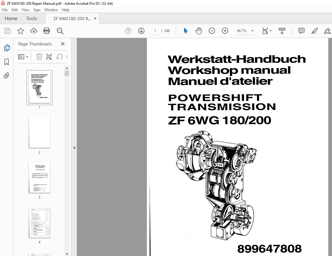
ZF 6WG 180/200 Powerful Transmission Workshop Manual 899647808 PDF
$28.95
ZF 6WG 180/200 Powerful Transmission Workshop Manual 899647808 – PDF DOWNLOAD
Description
ZF 6WG 180/200 Powerful Transmission Workshop Manual 899647808 – PDF DOWNLOAD
FILE DETAILS:
ZF 6WG 180/200 Powerful Transmission Workshop Manual 899647808 – PDF DOWNLOAD
Language : English
Pages : 248
Downloadable : Yes
File Type : PDF
IMAGES PREVIEW OF THE MANUAL:
![]()
![]()
![]()
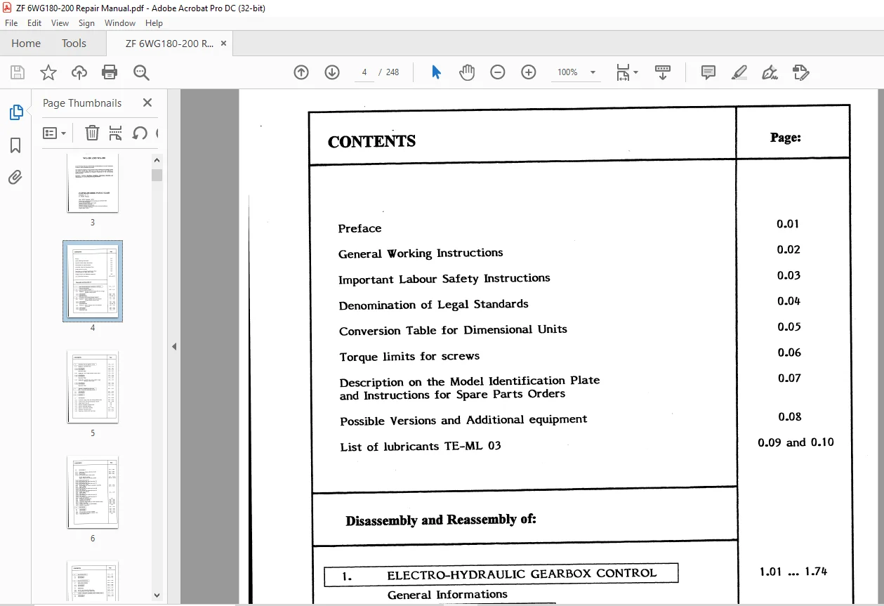
TABLE OF CONTENTS:
ZF 6WG 180/200 Powerful Transmission Workshop Manual 899647808 – PDF DOWNLOAD
Preface
General Working Instructions
Important Labour Safety Instructions
Denomination of Legal Standards
Conversion Table for Dimensional Units
Torque limits for screws
Description on the Model Identification Plate
and Instructions for Spare Parts Orders
Possible Versions and Additional equipment
List of lubricants TE-ML 03
Disassembly and Reassembly of:
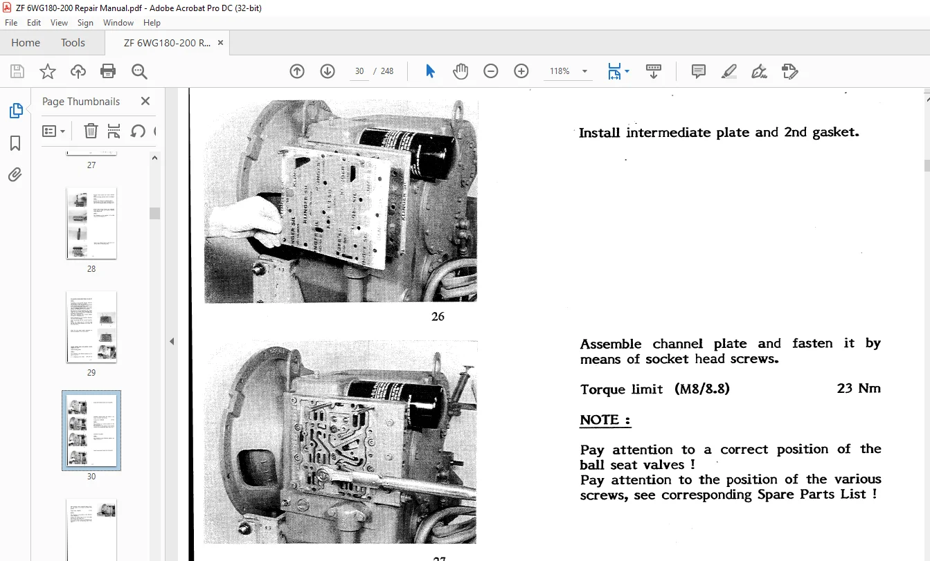
1 ELECTRO-HYDRAULIC GEARBOX CONTROL
General Informations
1 1 Cast-iron gearbox control
1 1 1 Version I : Standard Version (without WK and 2-stage
pressure control valve)
t t t t DISASSEMBLY
1 1 1 2 REASSEMBLY
Illustrated Table
1 2 Aluminium sand-casting gearbox control
1 2 1 Version I : with 4 solenoid valves and attached
2-stage pressure control valve
1 2 1 1 DISASSEMBLY
1 2 1 2 REASSEMBLY
Illustrated Table
1 2 2 Version II : with 5 solenoid valves and attached
WK-Valve
1 2 2 1 DISASSEMBLY
1 2 2 2 REASSEMBLY
Illustrated Table
1 3 Aluminium die-cast gearbox control I 1 39 1 74
1 3 1 Version I : with WK-Valve 1 39 1 52
1 3 1 1 DISASSEMBLY 1 39 1 41
1 3 1 2 REASSEMBLY 1 42 1 52
Illustrated Table 1 49 1 51
1 3 2 Version II : with 2-stage pressure control valve 1 53 1 62
1 3 2 1 DISASSEMBLY 1 53 1 54
1 3 22 REASSEMBLY 1 55 1 62
illustrated Table 1 59 1 61
1 3 3 Version Ill : with Wk-Valve and variable 2-stage 1 63 1 74
pressure control valve
1 3 3 1 DISASSEMBLY 1 63 1 65
1 3 3 2 REASSEMBLY 1 66 1 74
Illustrated Table 1 72 1 73
2 TORQUE CONVERTER WITH WK 2 01 2 12
(WK = Converter connecting clutch)
2 1 DISASSEMBLY 2 01 2 03
2 2 REASSEMBLY 2 04 2 12
I 3 GEARBOX I 3 01 3 80
3 1 DISASSEMBLY 3 01 3 20
3 1 1 Converter charge pump and control pressure pump 3 01 3 06
3 1 2 Coaxial power take-off (mechanical control} 3 06 3 08
3 1 3 Lateral power take-off 3 09
3 1 4 Remove emergency steering pump 3 10
3 1 5 Remove multi-disk clutches 3 11
3 1 6 Remove countershaft assembly 3 11 …3 12
3 1 7 Dismantle multi-disk clutch 3 13 3 14
3 1 8 Final drive, Version with drum brake
3 2 REASSEMBLY 3 21 3 80
3 2 1 Final drive, Version with drum brake 3 21 3 29
3 2 2 Speedometer 3 30 3 31
3 2 3 Clutch K4/K3 3 33 3 43
3 2 3 t Pre-assemble plate carrier K4/K3
PLATE INSTALLATION 3 35 3 36 d
TABLE FOR PLATE INSTALLATION 3 36 a 3 36 d
3 2 3 2 Install plate pack K4
3 2 3 3 Pre-assemble and install spur gear K4
3 2 3 4 Install plate pack K3
3 2 3 5 Pre-assemble and install spur gear K3
3 2 3 6 Install clutch K4/K3
3 2 4 Pre-assemble and install countershaft assembly 3 44 3 45
3 2 5 Clutch KR/K2 3 45 3 50
3 2 5 1 Plate pack KR
3 2 5 2 Pre-assemble and install spur gear KR
3 2 5 3 Plate pack K2
3 2 5 4 Pre-assemble and install spur gear K2
3 2 5 5 Install clutch KR/K2
3 2 6 Clutch KV/Kl 3 51 3 59
3 2 6 1 Plate pack KV
3 2 6 2 Pre-assemble and install spur gear KV
3 2 6 3 Plate pack K 1
3 2 6 4 Pre-assemble and install spur gear K 1
3 2 6 5 Install clutch KV /K 1
3 2 7 Emergency steering pump 3 60
3 2 8 Lateral power take-off 3 61 3 64
3 2 9 Converter control valve 3 64 3 65
3 2 t 0 Converter charge pump and control pressure pump 3 65 3 72
3 2 11 Engine connection 3 72 3 73
3 2 12 Coaxial power take-off (controllable) 3 73 3 78
3 2 13 Inductive transmitter 3 79
丨4 RETARDER I 4 01 4 14
4 1 DISASSEMBLY 4 01 4 05
4 2 REASSEMBLY 4 06 4 14
4 2 1 Pre-assemble and attach retarder 4 06 4 12
4 2 2 Pre-assemble and attach retarder valve 4 12 4 13
4 2 3 Install Delivery lines
5 AXLE DECLUTCH I 5 01 5 12
5 1 DISASSEMBLY 5 01 5 04
5 2 REASSEMBLY 5 05 5 12
I 6 AXLE DIFFERENTIAL I 6 01 6 22
6 1 Shift-control housing 6 01 6 08
6 1 1 DISASSEMBLY 6 01 6 04
6 1 2 REASSEMBLY 6 04 6 08
6 2 Differential 6 09 6 21
6 2 1 Remove and dismantle differential 6 09 …6 13
6 2 2 Pre-assemble and install differential 6 14 6 21
I 7 POWER TAKE-OFF CONTROLLABLE UNDER LOAD I 7 01 7 12
7 1 DISASSEMBLY 7 01 …7 05
7 2 REASSEMBLY 7 06 7 12
DESCRIPTION:
ZF 6WG 180/200 Powerful Transmission Workshop Manual 899647808 – PDF DOWNLOAD
PREFACE:
- This documentation has been developped for the skilled Serviceman, trained by the Zahnradfabrik:
Passau for the Repair and Maintenance operations on ZF-Units. - Treated is a ZF-Serial product according to the design stage of the date of Edition.
- However, due to further technical developments of the product, the repair of the unit at your
disposal could require di:fferents steps as well as other adjustment and testing specifications. - Therefore, we recommend to commit your ZF-Product to Masters and to Setvice-men, whose
practical and theoretical training is constantly completed to the actual situation in our Training
School.
GENERAL WORKING INSTRUCTIONS:
- During all operations, pay attention to cleanJiness and skilled working.
- Therefore, Transmissions, removed from the vehicle, must be cleaned prior to open them.
- We assume that the Special Tools, specified by ZF, will be used.
- The Special Tools have a 10-digit Subject-No. and are availabe from ZF-Passau.
After the disassembly, all components must be cleaned, especially comers, cavities and recesses of
housing and covers. - The old sealing compound must be carefully removed.
- Check lubricating holes, grooves and pipes for free passage. They must be free of residues,
foreign material or protective compounds. - The latter refers expecially to new parts.
- Parts which have been inevitably damaged in a disassembly operation, must be generally replaced
by new ones, e.g. : rotary seal rings, 0-Rings, U-Secti.on rings, cap boots, protective caps etc.. - Components such as roller bearings, thrust washers, synchronizing parts etc. which are subject to
normal wear in automotive operation, must be checked by the skilled Setviceman.
Hew沮decide if the parts can be reused.
ZF 6WG 180/200 POWERFUL TRANSMISSION WORKSHOP MANUAL 899647808 PDF:
S.V 1/04/2025