
Ziehm Vision RFD Software Versions 6 and 7 Service Manual
Original price was: $39.95.$23.95Current price is: $23.95.
632-page service manual for Ziehm Vision RFD systems running Software Versions 6 and 7, covering mobile stand and monitor cart service, power supply, generator, flat-panel detector, collimator, Vision Center, image memory, DICOM configuration, adjustments, error messages, and work instructions.
Description
File Details
- Manual type: Service Manual
- Brand: Ziehm Imaging GmbH
- Model: Ziehm Vision RFD
- Software versions covered: 6 and 7
- Document number: 280727
- Revision/date: 01/02/2017
- Language: English
- Page count: 632
- File format: PDF
Chapters Covered
- 0 Classification Mobile Stand / Monitor Cart
- 1 Warnings and Important Information
- Safety Instructions
- Warnings
- Tests Required After Service
- Displaying the System Software Versions and Creating Report Package
- Definitions and Abbreviations
- 2 General
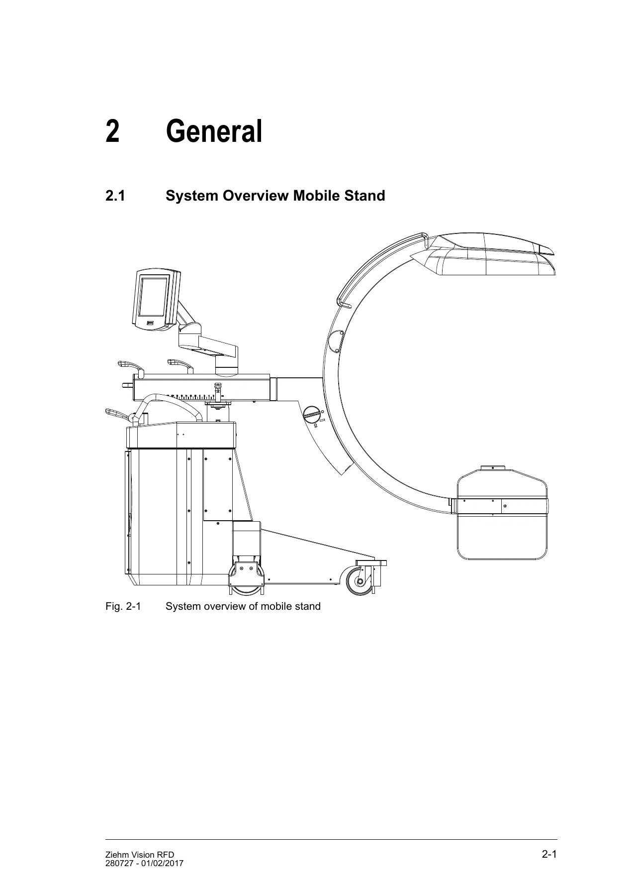
- System Overview Mobile Stand
- Board Numbers
- CAN Bus
- CAN Bus Distribution in the Mobile Stand with aSi Detector
- CAN Bus Distribution in the Mobile Stand with CMOS Detector
- CAN Bus Distribution in the Monitor Cart
- Block Diagrams for CAN Fault Line and Shutdown
- 3 Connections Mobile Stand
- XP0 Cable
- CAN RJ45-RJ45 and CAN-Molex-RJ-45
- Wiring of Hand and Foot Switches
- Wiring Mobile Stand
- Power Supply, Pre-Power Supply, Flat-panel Detectors, Generator, Vision Track, Vision Center
- 4 Power Supply Mobile Stand
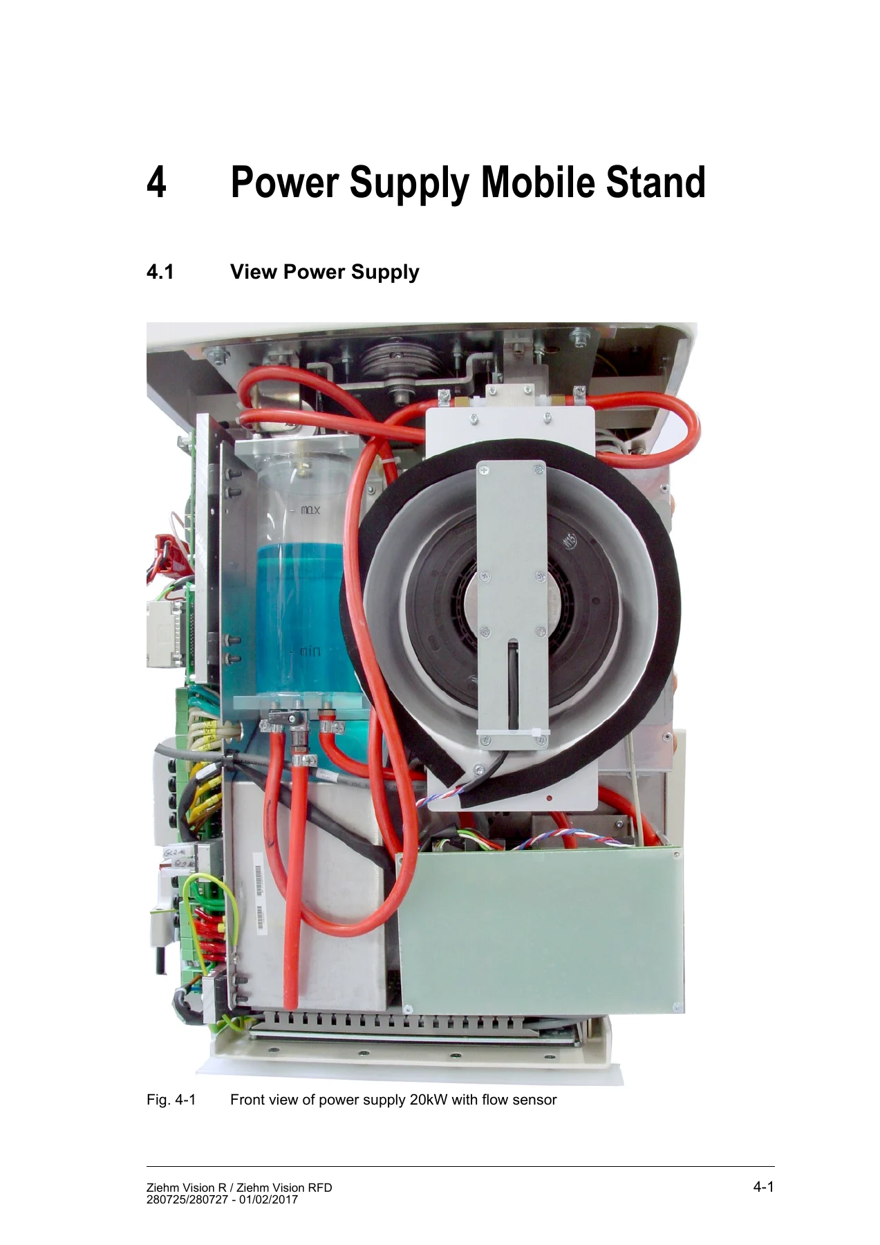
- View Power Supply
- Functions of the Power Supply
- Wiring Diagrams and Block Diagrams
- Pre-Power Supply
- Power Factor Correction
- DC 24V Supply Unit FG 9938
- U579 Power Supply Control Board
- U597 Pump and Fan Control
- Mains Transformer T21
- Capacitor Rack
- 5 Main Interface
- Module 2 Main Interface
- Main Interface Functions
- Hand/Foot Switch Commands to the Image System
- HW Settings
- LED Indicators
- Connectors
- Hardware Radiation Logic
- U648 Layout and Schematics
- 6 Flat-panel Detector
- aSi (PaxScan) Flat-panel Detectors
- PaxScan Hardware
- Gain/Offset Calibration
- Serial Interface 2
- FD3030 Panel Modes
- Configuration Check
- Bypassing GigaLink
- CMOS Flat-panel Detector
- U707 CCU
- Gain Calibration and Manual Dead Pixel
- 7 X-ray Generator
- 7.5 kW and 20/25 kW Generator Overviews
- Generator Wiring Diagram
- Interface Generator – Mobile Stand
- Self Tests
- General PCBs
- U565, U564, U561/U624, U563, U562
- U565 and U518 Features
- Pulse Technology
- X-ray Tube Filament Control
- Heat Unit Calculator
- Water Pump Control
- Measuring kV and mA
- Adjustment of Center Beam
- 8 Asymmetric Collimator
- View of Asymmetric Collimator
- Block Diagram
- U659 Connectors, Switches, LED Indicators
- Changing the Collimator
- Mechanical Centering
- Collimator and Preview Size Adjustment
- Automatic Cropping
- DAP Calculated Option
- 9 TFT Vision Center
- View of Vision Center
- Vision Center Main Parts
- Block Diagrams with U687 and U718
- Connectors and Interconnection Board
- Vision Center Wiring
- Remote Vision Center
- 10 Monitor Cart
- Monitor Cart 6
- Monitor Cart 6 Detail View
- Monitor Cart 6 Option Endo
- 11 Connections Monitor Cart
- Wiring Diagrams MC6
- Wiring XP0 and Power Supply
- Wiring Image Memory V2 1k and NGIS MiRa
- Wiring Option FD + CP2LC
- Wiring User Interface, Flatscreen Monitors, Media Options
- Yellow RJ-45 Network Cables
- 12 Video Documentation
- UP 991 and UP971 Configuration
- 13 Monitors
- 19-inch DUO Monitor
- 26-inch Flatscreen Monitor Radiance G2 HB
- 14 Power Supply Monitor Cart
- View of Power Supply
- Main Components of the Power Module 10
- Module 10 with HC08 Controller on U539
- Connectors, LED Indicators, Jumpers, Fuses
- Mains Input Voltage Selection
- U539h and U539j Schematics
- U539-U579 Power Switching Block Diagram
- Software Flowcharts and Status Monitoring
- 15 Image Memory System
- NGIS MiRa
- V2 1K
- U578 Interface
- U674 Framegrabber
- Regulation Block Diagrams for aSi and CMOS Panels
- 16 DICOM Configuration Manual
- Network Parameters
- Entering DICOM Configuration
- Configuring DICOM Servers
- Media, Storage, Storage Commitment, Query/Retrieve, Worklist, MPPS, Basic Grayscale Print
- Cloning Servers and Navigation Server
- DICOM Verification
- DICOM Conformance Statement
- 17 Software Tools
- Vision Studio
- Service Toolbar
- Generator Controller Reprogram
- Vision Center Service Settings
- USB Service Key
- 18 Adjustment Instructions
- Dose Adjustment
- Video Adjustment
- Input Boxes on Dose, Grid, ZAIP 2, Collimator, Other, Fluoro and FD Tabs
- Adjusting Computed DAP / Air Kerma
- Adjusting Measured DAP
- 19 Error Messages & Fault Finding
- Error Message List
- Fuse List
- Fault Finding for Power and Startup, Generator, CAN Bus, and Image System
- Measurements on the CAN Bus
- 20 Work Instructions
- Active Cooling System
- Filling and Draining the Cooling System of 7.5 kW Systems
- Filling and Draining the Cooling System of 20/25 kW Systems
- Checking the Liquid Level
- Replacing the Cooling Liquid
This Ziehm Vision RFD Software Versions 6 and 7 Service Manual is organized as a technical reference for service work across the mobile stand and monitor cart. It combines board-level identification, wiring and block diagrams, connector pinouts, LED and fuse references, generator and flat-panel detector service information, collimator adjustment, Vision Center and image memory details, DICOM configuration, software service tools, dose and video adjustment instructions, error messages, fault-finding guidance, and cooling-system work instructions. The chapter structure supports both targeted troubleshooting and larger service tasks, with module-specific sections for the power supply, main interface, generator, collimator, monitor cart power supply, and image memory system. The manual also includes CAN bus distribution and shutdown block diagrams, helping technicians trace communication and power-control paths through the system.
Service and Diagnostic Use
The Ziehm Vision RFD Software Versions 6 and 7 Service Manual covers practical service references such as board numbers, CAN module numbers, connector assignments, test points, jumper and DIP switch settings, LED status meanings, fuse locations, and error code descriptions. It documents the main interface, pre-power supply, power supply control board, pump and fan control, X-ray generator boards, asymmetric collimator control, TFT Vision Center, monitor cart power module, and image memory options. Adjustment sections address dose, video, computed DAP and air kerma, measured DAP, and center beam alignment, while the work instructions cover the active cooling system and filling or draining procedures for 7.5 kW and 20/25 kW systems.
Get the Ziehm Vision RFD Service Manual
IMAGES PREVIEW
This PDF service manual gives technicians a single reference for maintaining, diagnosing, adjusting, and repairing Ziehm Vision RFD systems running Software Versions 6 and 7. It supports module-level troubleshooting, board replacement reference, wiring checks, CAN bus fault finding, generator and detector service, collimator calibration, DICOM setup, and cooling-system maintenance. Keep the correct procedures and specifications on hand for service work instead of relying on memory or incomplete notes. The manual is delivered as an instant PDF download after payment, with no shipping, and can be viewed on a computer, tablet, or phone and printed when a bench copy is needed.
Reviews
There are no reviews yet.