

Varian Clinac 2000C/R 2100C/D 2300C/D 21EX 23EX Installation Data Package IDP PDF Download
Original price was: $39.95.$24.95Current price is: $24.95.
85-page English Varian Installation Data Package Section One for Clinac 2000C/R, 2100C(/D), 2300C/D, 21EX and 23EX linear accelerators. Covers treatment-room planning, shielding, equipment layout, rigging, base-frame installation, electrical power, interconnection wiring, cooling, HVAC, compressed air, component dimensions/weights, shipping data, pre-installation checklists and respiratory gating installation. Instant PDF download.
Description
Varian Clinac Installation Data Package – Section One
This 85-page English Varian Medical Systems Installation Data Package (IDP), Section One provides detailed equipment and facility-planning information for Clinac 2000C/R, 2100C(/D), 2300C/D, 21EX and 23EX medical linear accelerators. The cover identifies this edition as English Version, May 2003.
This is not a routine operating manual or general service manual. It is an engineering and installation-planning package intended to help customers, architects, physicists, electrical engineers, mechanical engineers, structural engineers and contractors understand the facility requirements associated with installing the listed Varian Clinac systems.
The document combines architectural layouts, radiation-shielding reference tables, equipment clearances, base-frame and pit details, cable-routing requirements, electrical specifications, interconnection wiring, HVAC and plumbing data, cooling-system requirements, compressed-air specifications, equipment weights and dimensions, shipping information, pre-installation checklists and a supplemental Respiratory Gating installation section.
Clinac Models Covered by Section One
- Clinac 2000C/R
- Clinac 2100C(/D)
- Clinac 2300C/D
- Clinac 21EX
- Clinac 23EX
The document also contains references to Silhouette configurations where the same requirement or component information applies.
Important Clinac 6EX Scope Note
This Section One IDP is not the primary Installation Data Package for Clinac 6EX. The document itself explains that the Varian IDP is divided into multiple sections and identifies:
- Section 1: Clinac 2000C/R, 2100C(/D), 2300C/D, 21EX and 23EX
- Section 2: Clinac 600C(/D), 4EX and 6EX
Therefore buyers looking specifically for complete Clinac 6EX equipment/facility installation requirements should obtain Section Two rather than assuming the main Section One drawings apply to 6EX.
The final Respiratory Gating appendix does separately identify Clinac 600C/D and 6EX as machines that may be connected to the Varian Respiratory Gating system. That supplemental gating information does not convert the main Section One package into a complete 6EX IDP.
What the Installation Data Package Is For
The stated purpose of the IDP is to help customers, architects, engineers and contractors understand Varian equipment requirements and facility-design issues. The material is intended to support planning and construction-document preparation before delivery and installation of the accelerator.
The package addresses the interfaces between the Clinac and the building, including:
- Treatment-vault layout
- Radiation shielding
- Equipment clearances
- Isocenter location
- Rigging access
- Floor and base-frame construction
- Electrical supply
- Safety circuits
- Cable conduits and pull boxes
- Cooling water
- HVAC
- Compressed air
- Control-area equipment
- Patient-monitoring systems
- Laser positioning lights
- Room lighting
- Accessory storage
- Pre-installation readiness
Complete Contents of the Clinac Section
The table of contents identifies major drawings and planning documents including:
- Typical Room Shielding Tables
- Typical Room Isometric View
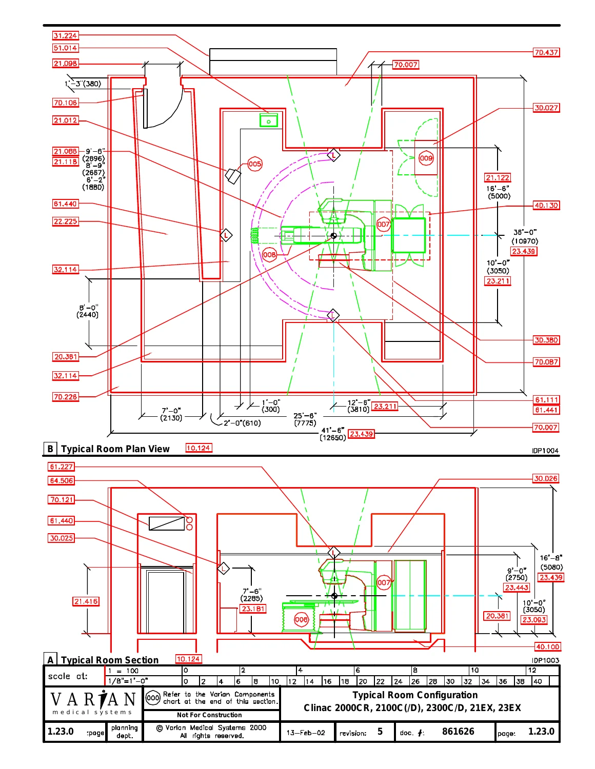
- Typical Room Configuration
- Overlay – Shipping Configuration
- Overlay – Plan View
- Overlay – Elevations
- Typical Control Equipment Casework
- Typical Remote Workstations
- Laser Positioning Lights
- General Room Storage Requirements
- Typical Accessory Storage Dimensions
- Typical Closed Circuit Television System
- In-Room Monitor
- Modulator Cabinet
- Base Frame Pit and Installation
- Base Frame Cable Access Details
- Cable Access Diagram
- Typical Lighting, Service and Safety Devices
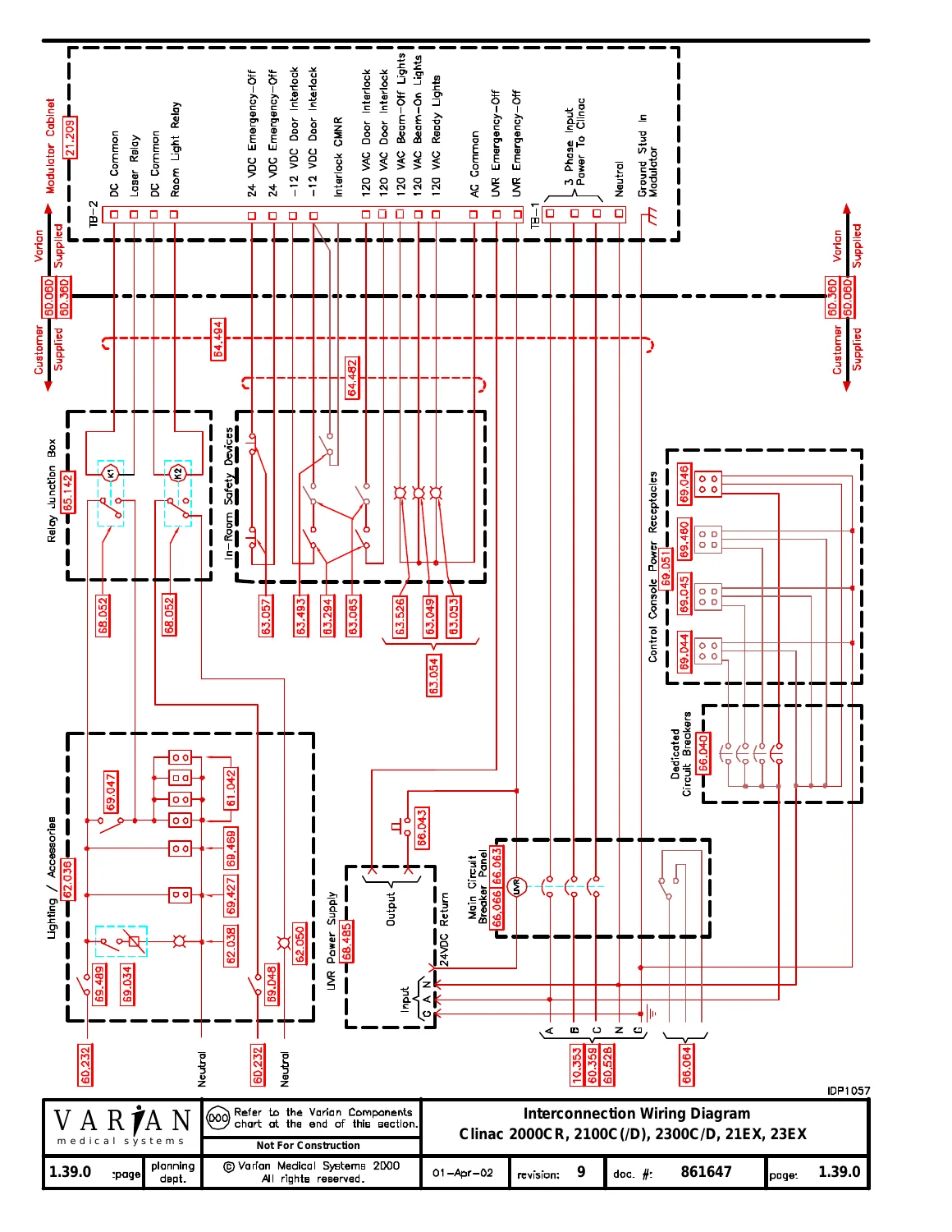
- Interconnection Wiring Diagram
- HVAC and Plumbing Requirements
- Varian-Supplied Component Information Table
- Clinac Pre-Installation Checklist
- Clinac Shipping List
- Page Index
General Installation Planning Information
The introductory sections explain how Varian installation planning was structured and how the various parties involved in a Clinac project were expected to use the IDP.
The document describes responsibilities for:
- Architectural and engineering construction documents
- Radiation shielding
- Structural alterations
- Electrical and mechanical services
- Plumbing
- Fire protection
- HVAC
- Compressed air
- Lighting and power distribution
- CCTV and intercom systems
- Base-frame shipment and installation
- Equipment rigging
- Varian interconnect cable installation
- Network cabling
- Equipment assembly and run-up
Clinac Options and Configuration Planning
The Section One notes identify several options and configuration decisions that should be determined early in the facility-design process.
For the listed dual-energy Clinac systems, the manual identifies examples including:
- Clinac 2100C maximum photon-energy choices: 10, 15 or 18 MV
- Clinac 2300C/D maximum photon-energy choices: 15, 18 or 20 MV
- Beamstopper
- VARiS
- PortalVision
- Multileaf Collimator
- Respiratory Gating
- Laser positioning lights
- CCTV system
- Power conditioner
- Equipment rigging
- Base-frame grouting
- Final utility connections
Radiation Shielding Reference
The IDP includes a dedicated Typical Room Shielding Tables section with planning data for the listed Clinac systems.
The shielding material includes:
- Typical primary-barrier thicknesses
- Typical secondary-barrier thicknesses
- Concrete shielding information
- Lead and steel shielding ratios
- Tenth Value Layer information versus X-ray energy
- Typical minimum Clinac room door shielding
- Neutron dose-equivalent information
- X-ray beam-quality reference values
The document discusses shielding for low- and dual-energy installations, maze design, shielded doors, duct penetrations and the additional neutron-shielding considerations associated with higher photon energies.
It repeatedly makes clear that final radiation-shielding adequacy is a site-specific matter to be determined and approved by the facility’s Physicist of Record. The drawings are marked Not For Construction and are provided as planning information rather than final site-specific structural or radiation-protection design documents.
Beamstopper and Primary Barrier Planning
The IDP explains the facility implications of an optional Clinac beamstopper. Where the applicable beamstopper is installed, it can reduce the need for increased primary barrier shielding, allowing the vault to be designed principally around secondary radiation shielding according to the applicable site design.
The document also warns that the beamstopper can interfere with some couch movements at certain gantry positions and may restrict installation of some accessory options.
Typical Treatment Room Layouts
The package contains detailed plan, section and isometric drawings showing a typical Clinac treatment room.
These drawings identify relationships among:
- Clinac Stand and Gantry
- Exact Treatment Couch
- Beamstopper where fitted
- Modulator Cabinet
- Control equipment
- Base-frame pit
- Isocenter
- Maze and vault entrance
- Primary and secondary barriers
- Laser positioning lights
- CCTV equipment
- In-Room Monitor
- Emergency-off controls
- Service and utility locations
Isocenter and Equipment Clearances
Isocenter is treated as the primary facility reference point for installation planning.
The document gives:
- Standard Clinac isocenter height: 4 ft 3 in (1295 mm)
- Optional lowered isocenter: 4 ft 1 in (1245 mm)
Room drawings and planning notes also address:
- Recommended couch rotation clearances
- Maximum and minimum couch arcs
- Equipment-to-wall clearances
- Ceiling clearances
- Service access
- Modulator Cabinet clearance
- Total-body-irradiation space considerations
- Equipment entrance and rigging clearances
The manual states that the standard Exact Treatment Couch has a maximum couch arc clearance of 9 ft 6 in (2896 mm), a maximum arc of 8 ft 9 in (2667 mm) with the Extension Panel removed and a minimum couch arc clearance of 6 ft 2 in (1880 mm).
Equipment Rigging and Access
A Clinac installation involves extremely large and heavy assemblies, so rigging access receives substantial attention.
The manual addresses:
- Clear path from unloading location to treatment vault
- Maze and doorway clearances
- Standard three-piece breakdown
- Optional four-piece breakdown
- Shipping configurations
- Stand/Gantry handling
- Counterweight or beamstopper assemblies
- Base-frame installation
- Storage of equipment before installation
The Clinac pre-installation checklist specifies a clear room entrance opening of approximately 4 ft by 7 ft for equipment access.
Base Frame, Equipment Pit and Structural Requirements
The package contains detailed drawings for the Base Frame Pit and Installation and Base Frame Cable Access.
The document explains that a steel frame anchors the Clinac Stand, Gantry and Couch to the building structure. The frame is installed in a recessed pit, leveled and grouted into position.
Planning information addresses:
- Base-frame pit location
- Anchorage
- Grouting
- Cable access
- Utility interfaces
- Structural support
- Upper-floor installation considerations
- Seismic anchorage responsibility
Control Equipment and Workstation Planning
The IDP includes drawings and dimensional information for control equipment casework and remote workstations.
Equipment represented includes combinations of:
- Clinac Control Console
- Clinac Video Monitor
- Dedicated keyboard
- Clinac Electronics Cabinet
- Log printer
- VARiS equipment
- Multileaf Collimator workstation equipment
- PortalVision equipment
- Server and network equipment
Laser Positioning Lights
The manual provides dedicated installation information for laser positioning lights used to align patient body markings with the treatment isocenter.
The arrangement includes:
- Two side-wall lasers located at isocenter height
- Overhead laser positioned over isocenter
- Sagittal laser on the wall at the longitudinal couch axis
- Laser electrical receptacles
- Relay-control requirements
- Mounting and recess planning
The sagittal laser is identified as typically mounted approximately 7 ft 6 in (2285 mm) above the floor.
Treatment Room Storage and Accessories
The IDP addresses the practical storage required around an operating Clinac treatment room.
Storage subjects include:
- Electron applicators / cones
- Wedges
- Field-defining devices
- Block trays
- Patient-positioning aids
- Linen
- Installation equipment and material
The document recommends planning storage around the treatment workflow to minimize unnecessary movement during patient setup.
CCTV, Intercom and Patient Monitoring
The planning package includes dedicated information for treatment-room patient monitoring.
Coverage includes:
- One- or two-camera CCTV systems
- Typical camera locations
- Camera power and signal conduit
- Control-console monitors
- Patient privacy considerations
- Two-way intercom
- In-room intercom locations
- Control-area push-to-talk functions
- Power and conduit planning
Lighting and Safety Devices
The Typical Lighting, Service and Safety Devices section shows the arrangement of treatment-room electrical and safety systems.
Coverage includes:
- Room lighting
- Setup lighting
- Emergency lighting
- Laser circuits
- Beam-On warning lights
- Ready light provisions
- Emergency-Off switches
- Door interlocks
- Door operator controls
- Service receptacles
- In-Room Monitor receptacle
- CCTV receptacles
The manual discusses the need to position Emergency-Off switches so that personnel do not have to cross the primary beam path to reach a shutdown control.
Clinac Interconnection Wiring Diagram
One of the most technically useful drawings in the package is the Interconnection Wiring Diagram for Clinac 2000CR, 2100C(/D), 2300C/D, 21EX and 23EX.
The drawing and accompanying notes cover facility-side connections involving:
- Main circuit breaker
- Under-Voltage Release
- Emergency-Off circuit
- Door interlocks
- Beam-On lights
- Ready lights
- Room lighting control
- Laser positioning-light relay
- Modulator connections
- Control equipment
- Relay junction box
- Varian interconnect cables
The package differentiates customer-supplied wiring and Varian-provided circuits and provides installation notes concerning conductor routing, pull-box allowances and terminal-block interfaces.
Clinac Main Electrical Power Requirements
The document gives detailed electrical specifications for the listed Clinac systems.
Published requirements include:
- Typical 60 Hz input: 200 to 240 Vac, line-to-line, three-phase
- Typical 50 Hz input: 360 to 440 Vac, line-to-line, three-phase wye
- Frequency: 50 or 60 Hz ±1 Hz
- Maximum steady-state line-voltage deviation: ±5%
- Maximum phase-voltage imbalance: 3%
- Standby electrical load: approximately 3 kVA
- Ready/Energy Select load: approximately 20 kVA
- Beam-On load: approximately 45 kVA
- Long-time load: 45 kVA
- Estimated power factor: 90% or more
The guide also provides source-impedance information, grounding requirements, fault-current considerations and conductor information.
Main Circuit Breaker Information
The electrical section specifies the location and requirements for the Clinac Main Circuit Breaker Panel.
The panel is to be located within sight of and within 10 ft (3050 mm) of the Clinac control-equipment casework.
The manual identifies:
- G.E. 2100CBB150A Main Circuit Breaker Panel
- 150 A UVR breaker configuration for typical 208 Vac installations
- 80 A UVR breaker configuration for typical 400 Vac installations
- 24 VDC Under-Voltage Release power-supply requirements
Power Quality and Conditioning
The IDP explains that accelerator operation is sensitive to line-voltage variations and source impedance. It recommends an electrical supply survey before installation and discusses circumstances requiring isolation transformers or power conditioners.
Subjects include:
- Line-voltage stability
- Source impedance
- Power-line harmonic distortion
- Phase-controlled loads
- Electrical transients
- Transient suppression
- Isolation from problematic facility loads
Cable Access, Conduits and Pull Boxes
The cable-access drawings provide considerable detail for routing the large number of power, control and signal cables between the accelerator equipment.
Examples include:
- Conduits between In-Room Monitor and Control Console
- Conduit between Main Circuit Breaker Panel and Modulator
- Control Console to Base Frame cable routes
- Control Console to Modulator cable routes
- Base Frame to Modulator cable routes
- Relay junction-box connections
- Experimental / physics access conduit
- Future cable-access provisions
- Signal pull boxes
- Base Frame pull box
- Control Equipment pull box
- Modulator pull box
The IDP identifies multiple 1-inch, 2-inch and 4-inch conduit requirements according to cable route, with several cable runs limited to approximately 75 ft (22,900 mm).
Cooling System Requirements
The HVAC and Plumbing section contains detailed technical requirements for the accelerator cooling system.
For the Dual Energy Clinac configuration, published coolant heat loads include:
- Standby: 2 kW (6,830 Btu/hr)
- Mode Release: 10 kW (34,152 Btu/hr)
- Ready/Energy Select: 12.5 kW (42,690 Btu/hr)
- Beam-On: 25 kW (85,379 Btu/hr)
- Normal treatment-cycle heat dissipation to cooling water: 13.3 kW (45,422 Btu/hr)
The manual also specifies:
- 24-hour minimum cooling requirement
- Maximum incoming pressure
- Specified inlet/outlet pressure differential
- Typical incoming coolant temperature range
- Heat exchanger and internal coolant-loop operation
- One-pass versus closed-loop systems
- Domestic backup for closed-loop systems
- Cooling-water quality considerations
- Maximum glycol content
- Supply and return valve requirements
- Flow-meter provision
- Condensation and dew-point considerations
The internal coolant loop is maintained at approximately 104°F (40°C) through the system’s temperature-control arrangement.
HVAC and Room Ventilation
The ventilation section provides both heat-removal and ozone-control requirements.
The manual states that approximately four to six air changes per hour are normally required to keep ozone at undetectable levels depending on room size and circulation efficiency.
Published room air heat loads include:
- Stand/Gantry during Ready/Energy Select and Beam-On: 5.0 kW
- Stand/Gantry during Mode Release: 1.5 kW
- Stand/Gantry during Standby: 1.0 kW
- Modulator during Beam-On: 3.0 kW
- Modulator during other states: 0.5 kW
- Clinac Control Console: 1.0 kW
Environmental Requirements
The document specifies an operating environment of:
- Relative humidity: 15% to 80%, non-condensing
- Room temperature: 60°F to 80°F (16°C to 27°C)
It also addresses static-electricity considerations for flooring near sensitive electronic equipment.
Compressed Air Requirements
Compressed air is required for the documented Clinac 2000CR, 2100C(/D), 2300C/D, 21EX and 23EX configurations and applicable Silhouette systems.
The package specifies:
- Instrument-quality dry compressed air
- Dew-point requirements
- Particle/aerosol-size requirements
- Minimum flow
- Pressure requirements
- Recommended storage-tank capacity
- Termination of the air line at the Base Frame pit
Fire Protection and Facility Safety
The package discusses fire-protection planning around accelerator equipment, including the risks associated with sprinkler discharge or leakage into equipment areas.
It discusses:
- Smoke and heat detection
- Type C fire extinguisher provision
- Sprinkler-placement considerations
- Dry pre-action concepts where required
- Protection of accelerator components from water discharge
Varian Component Dimensions, Weights, Power and Noise
A multi-page Varian Component Table provides planning information for major Clinac and optional equipment.
For each applicable component the table may provide:
- Width
- Height
- Depth
- Weight
- Maximum wattage
- Maximum dBA
Major accelerator equipment listed includes:
- Clinac Video Monitor
- Clinac Control Console
- Clinac Dedicated Keyboard
- Clinac Electronics Cabinet
- Clinac Log Printer
- Clinac In-Room Monitor
- Clinac Dual Energy Stand/Gantry Assembly
- Exact Treatment Couch
- Modulator Cabinet
- Dual Energy Clinac Base Frame
Additional tables include workstation, MLC, PortalVision and VARiS components.
Examples of Installed Component Data
The table identifies the Clinac Dual Energy Stand/Gantry Assembly at approximately 21,300 lb (9,660 kg), the Exact Treatment Couch at approximately 1,357 lb (615 kg), the Modulator Cabinet at approximately 1,800 lb (816 kg) and the Dual Energy Clinac Base Frame at approximately 2,100 lb (952 kg).
The document cautions that component dimensions and weights are subject to change and should be verified against the exact equipment ordered.
Clinac Pre-Installation Checklist
The package contains a detailed checklist intended to verify facility readiness before accelerator shipment and installation.
Checklist items include:
- Planning drawing review
- Accelerator/radiation license
- Treatment-room door and hardware
- Rigging opening and access
- Base-frame installation and grouting
- Correct conduit number and size
- Varian interconnect cables
- Relay junction box
- Room and setup lighting
- Door interlocks
- Emergency-Off buttons
- Warning lights
- Laser wiring and mounting
- In-Room Monitor provision
- Water coolant supply
- HVAC operation
- Compressed air
- Utility trades availability
- Wall and ceiling completion
- Treatment-room storage
- Equipment riggers
- Rig-path clearance
- Main power and breaker panel
- Control-area completion
- Remote-diagnostics telephone line where applicable
- Electronics-cabinet ventilation
- Secure installation storage
- Construction-dust isolation
- Physicist scheduling for radiation survey
- Physicist and dosimetry equipment availability for acceptance testing
Clinac Shipping List and Rigging Weights
The IDP contains a detailed Clinac shipping list showing approximate shipping dimensions and weights for major assemblies.
The list distinguishes:
- Standard three-piece breakdown
- Optional four-piece breakdown
- Remaining Clinac equipment
- Fiberglass gantry panels
Standard Three-Piece Breakdown Examples
- Drive Stand/Gantry: approximately 13,000 lb (5,896 kg)
- Counterweight: approximately 6,105 lb (2,769 kg)
- Beamstopper: approximately 6,700 lb (3,039 kg)
- Electronic rack: approximately 1,070 lb (485 kg)
The listed total for the standard three-piece arrangement is approximately 26,875 lb (12,188 kg).
Optional Four-Piece Breakdown
The optional four-piece configuration separates the Stand and Gantry to reduce the space required to move the accelerator through the building and treatment-room access route.
The shipping list provides individual dimensions and weights for the Stand, Gantry, Counterweight or Beamstopper, Electronics Rack, Modulator, Console, Klystron, Exact Couch assemblies, Base Frame, RF Driver and other installation components.
Respiratory Gating / Real-Time Position Management Supplement
The final section of this PDF contains facility-planning information for the Varian Respiratory Gating / Real-Time Position Management system.
The document explains that the system uses a video camera and real-time digital image processing to monitor movement of a passive infrared-reflective marker placed on the patient’s chest or abdomen.
The gating section identifies possible interfaces with:
- Clinac 2100C/D
- Clinac 2300C/D
- Clinac 21/23 EX
- Clinac 600C/D
- Clinac 6EX
- Acuity
- CT Simulator
- Other simulators
Respiratory Gating Treatment Room Drawings
The gating supplement includes:
- Typical Clinac treatment-room section
- Typical Clinac treatment-room plan
- Clinac Interconnect Wiring drawing
- Respiratory Gating component table
- Gating camera ceiling-mount detail
- Gating camera wall-mount detail
- Gating cable and power requirements
- Gating workstation planning
- Respiratory Gating Pre-Installation Checklist
Respiratory Gating Equipment and Wiring
The gating interconnection drawing identifies components including:
- Respiratory Gating workstation computer
- Respiratory Gating power supply assembly
- Respiratory Gating camera and bracket
- Respiratory Gating switchbox assembly
- Respiratory Gating video monitor
- Respiratory Gating keyboard
- Control-room and treatment-room interconnections
The section also gives power, conduit and network requirements and shows how the camera may be installed from either a wall or ceiling support.
Respiratory Gating Pre-Installation Checklist
A dedicated final-page checklist covers readiness for gating installations in:
- Clinac treatment room
- Clinac control area
- Simulator room
- Simulator control area
- CT simulator room
- CT simulator control area
Items include camera and monitor brackets, conduit, cable lengths, power-supply access, workstation space, simulator interface information, control-area cabling and acceptance-test planning.
Who Will Find This IDP Useful
This package is particularly useful when planning, documenting, inspecting or understanding an installation involving one of the listed Clinac platforms. Its value comes from putting the building, electrical, mechanical, structural, radiation-protection, rigging and equipment-interface requirements into a single coordinated reference.
It can help a technical team understand how the accelerator interacts with the facility before installation and provides useful historical engineering information when evaluating an existing treatment vault or preparing for equipment relocation.
What This Manual Is
- A Varian Clinac Installation Data Package
- A facility-planning and engineering reference
- A Clinac room-layout drawing package
- A radiation-shielding planning reference
- An equipment-clearance and rigging reference
- A base-frame and equipment-pit planning guide
- An electrical-power requirements reference
- An interconnection-wiring reference
- A cooling, HVAC and compressed-air requirements guide
- A component dimensions/weights reference
- A Clinac pre-installation checklist
- A shipping dimensions and weights reference
- A supplemental Respiratory Gating installation reference
What This Manual Is Not
Understanding the document’s limitations is important before purchase.
- It is not the complete multi-section Varian Installation Data Package.
- It is specifically Section One.
- It is not the primary Clinac 6EX Installation Data Package; the document identifies 6EX under Section Two.
- It is not a Clinac service or repair manual.
- It is not a calibration or beam-tuning manual.
- It is not an accelerator troubleshooting manual.
- It is not a component-level circuit-board schematic collection.
- Its interconnection diagram documents installation interfaces and should not be confused with a complete internal electrical schematic set.
- It is not an illustrated replacement-parts catalog.
- The drawings are repeatedly marked Not For Construction and require site-specific review and adaptation by the responsible architects, engineers and physicist.
- Final radiation shielding and local regulatory compliance are outside the scope of the generic planning drawings and remain site-specific responsibilities.
Document Details
- Title: Installation Data Package – Section One
- Primary equipment: Clinac 2000C/R, 2100C(/D), 2300C/D, 21EX, 23EX
- Manufacturer identified in document: Varian Medical Systems
- Edition: English Version
- Cover date: May 2003
- PDF page count: 85
- Installation room drawings: Yes
- Radiation shielding tables: Yes
- Interconnection wiring diagram: Yes
- Electrical power requirements: Yes
- HVAC and plumbing: Yes
- Component weights and dimensions: Yes
- Shipping list: Yes
- Clinac pre-installation checklist: Yes
- Respiratory Gating supplement: Yes
Instant PDF Download
This product is supplied as an 85-page English digital PDF. After payment is completed, the document is available for immediate download and can be retained as a searchable engineering and installation reference on a compatible computer, tablet or mobile device.
No printed book is shipped. You receive the downloadable PDF document described on this page.




Reviews
There are no reviews yet.