


Zodiac ECE Power Master Box 702GC01 and 712GC01 Component Maintenance Manual
Original price was: $39.95.$24.95Current price is: $24.95.
Complete factory Component Maintenance Manual with Illustrated Parts List for the Zodiac Aerospace / ECE Power Master Box assemblies (Alpha Box part numbers 702GC01Y01, 702GC01Y02, 702GC01ADY02 and Beta Box part numbers 712GC01Y, 712GC01AAY) installed on CN235 aircraft 28V DC generation systems. Includes description and operation, schematics, bench testing, fault isolation flowcharts, disassembly, cleaning, check, repair, assembly torque specifications, and detailed parts lists.
Description
Zodiac ECE Power Master Box 702GC01 and 712GC01 Component Maintenance Manual
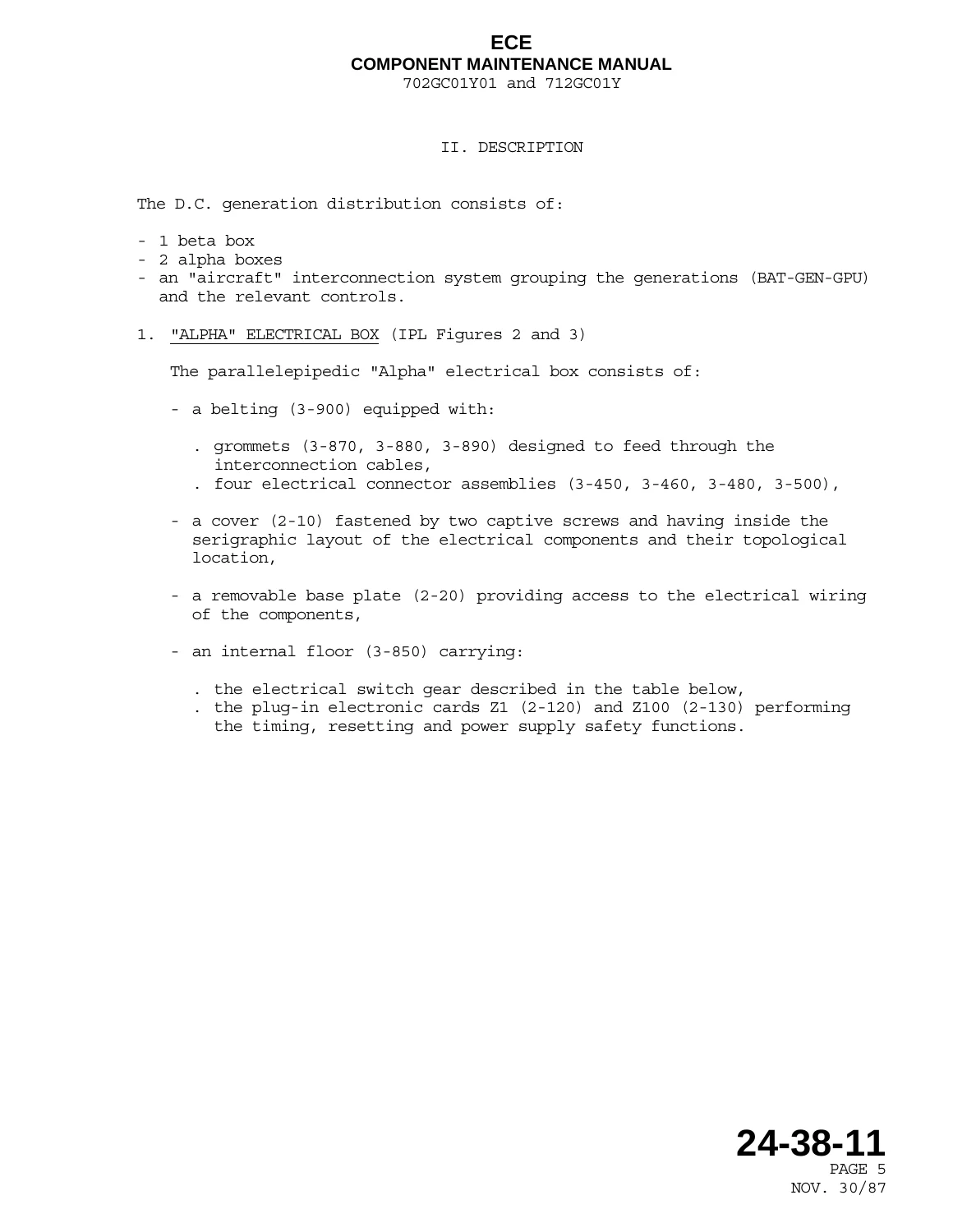
This technical publication serves as the official shop-level Zodiac ECE Power Master Box 702GC01 and 712GC01 Component Maintenance Manual (ATA 24-38-11), prepared in strict accordance with ATA 100 specifications. Designed specifically for workshop technicians, avionics specialists, and MRO repair stations maintaining the 28 V D.C. electrical power generation and distribution network of the CN235 aircraft, this manual provides all essential procedures required to inspect, troubleshoot, test, overhaul, disassemble, and reassemble the master control units. The installation integrates two parallelepipedic Alpha electrical boxes (part numbers 702GC01Y01, 702GC01Y02, and 702GC01ADY02) and one central Beta electrical box (part numbers 712GC01Y and 712GC01AAY), which together centralize 28V DC generator regulation, battery coupling, ground power input, cross-start sequencing, and primary feeder protection.
Document Details & Technical Specifications
- Manual Type: Component Maintenance Manual with Illustrated Parts List (CMM with IPL)
- Document Reference: ATA 24-38-11
- Manufacturer / Brand: ECE (L’Equipement et la Construction Electrique) / Zodiac Aerospace
- Equipment Designation: Power Master Box (Alpha Electrical Box & Beta Electrical Box)
- Covered Unit Part Numbers: 702GC01Y01, 702GC01Y02, 702GC01ADY02, 712GC01Y, 712GC01AAY
- Aircraft Application: CASA / IPTN CN235 28V DC Generation and Interconnection System
- Initial Issue Date: November 30, 1987
- Revision Status: Revision No. 6, dated January 30, 2010
- Language: English
- Page Count: 290 pages
- Format: Adobe PDF
Chapters Covered & Section Breakdown
- Description and Operation (Section 24-38-11, Pages 1–32)
- General: Definition of the Equipment, Functions Performed, Physical and Environmental Specifications
- Description: Alpha Electrical Box, Beta Electrical Box, D.C. Generation Aircraft Interconnection System
- Operation: Organization of D.C. Generation, Energization of Distribution Bars, Couplings and Decouplings, LH or RH Engine Starting, Monitoring and Protection, Distribution to the Use Point
- Testing and Fault Isolation (Section 24-38-11, Pages 101–174)
- General Flow Chart Symbols & Environmental Test Performance Conditions
- General Tests on the Alpha Box (Continuity, Logic, Contactor Switching, and Diagnostic Flowcharts ALPHA A1 to F2)
- Power Test Probes DM1 to DM4 and DM5 on the Alpha Box (Test Set-Ups & Current Injection Flowcharts)
- General Tests on the Beta Box (Continuity, Switching Logic, and Diagnostic Flowcharts BETA A1 to F4)
- DM10 Probe Power Test of the Beta Box (GPU Current Threshold Verification)
- Disassembly (Section 24-38-11, Pages 301–312)
- Tools and Equipment Required for Shop Teardown
- Procedures for Removing Alpha and Beta Boxes from Aircraft Structure
- Detailed Disassembly of the Alpha Box (Cover, Base Plate, Printed Circuit Assemblies, Fuses, Contactors, Relays, and Shunts)
- Detailed Disassembly of the Beta Box (Mounting Plates, Circuit Breakers, Heavy-Duty Shunts, and Contactor Groups)
- Cleaning (Section 24-38-11, Pages 401–402)
- Approved Cleaning Solvents, Naphtha Grade F, White Spirit Baths, and Low-Pressure Air Drying
- Check (Section 24-38-11, Pages 501–502)
- Mechanical Inspection, Engraving Verification, Surface Coating Adhesion, Hardware Locking, and Varnish Integrity
- Repair (Section 24-38-11, Pages 601–602)
- Defective Component Replacement and Post-Repair Verification Workflow
- Assembly (Including Storage) (Section 24-38-11, Pages 701–720)
- General Assembly Standards, Locking Varnish Applications, and Threadlock Chemical Selection
- Master Torque Specifications Table for Electrical Terminals (M3 through M10 Diameters)
- Complete Step-by-Step Reassembly of Alpha and Beta Boxes
- Aircraft Installation and Interconnection Hookup Procedures
- Short-Term and Long-Term Packaging, Desiccant Usage, and Environmental Storage Limits
- Illustrated Parts List (IPL) (Section 24-38-11, Pages TP 1001 to 1007-2)
- Introduction and Detailed Explanation of IPL Structure and ATA 100 Revision 20 Standards
- Vendor Code Index (VCI) identifying Original Component Manufacturers
- Equipment Designator Index (EDI) Cross-Referencing Circuit Schematics to Part Numbers
- Numerical Index (NI) with Total Quantity Required per Assembly
- Detailed Parts List (DPL) with Exploded Views: Figure 1 (Power Master Box), Figures 2 & 3 (Alpha Box), Figures 4 & 5 (Beta Box), and Figures 6 & 7 (Alpha and Beta Covers)
Together, this comprehensive technical document equips the maintenance engineer with deep architectural understanding, complete internal wiring schematics, and rigorous bench-level troubleshooting criteria. Rather than treating the Power Master Box as an unserviceable black box, the manual gives technicians complete autonomy to isolate faulty directional current relays, test internal printed circuit boards, replace individual contactor subassemblies, and certify returned-to-service equipment back to factory operational tolerances.
System Architecture, Bus Management & Operating Logic
The Zodiac ECE Power Master Box 702GC01 and 712GC01 Component Maintenance Manual details the full operational architecture that governs the CN235 twin-engine electrical distribution. Each aircraft installation features two symmetrical Alpha electrical boxes (one Left-Hand and one Right-Hand) measuring 515 mm by 300 mm by 146 mm and weighing 13.430 kg, alongside a central Beta electrical box measuring 455 mm by 300 mm by 176.8 mm and weighing 15.320 kg. Operating over a temperature envelope of -55°C to +70°C and altitudes up to 10,700 meters (33,105 feet), these units manage battery bus (BUS BAT), generator bus (BUS GEN), and load-sheddable hot bus (HOT BUS 1 and HOT BUS 2) power routing.
Operational coverage includes complete multi-mode starting sequences: standard battery starting (automatically placing batteries in series via contactor PSC at 1,500 rpm to deliver +56V DC, dropping back to parallel at 6,800 rpm), cross-generator starting (X START mode utilizing opposite-side starter-generator feed), and Ground Power Unit (GPU) starting with automatic generator and battery isolation. The text outlines precise operating parameters enforced by GCU1 and GCU2 regulators, requiring generator voltage of at least 22V, a differential threshold across contactor LC of 0.3V (VA – VB ≥ 0.3V), and engine speeds exceeding 7,300 ± 200 rpm before closing main generator line contactors. It further documents overvoltage trip logic (34V DC for 2 to 4 seconds) and instantaneous current protection thresholds: DM1 TR overload at 1,500A, DM2 BAT protection at 600A (150 ms trip), DM3 interside tie protection at 600A (110 ms trip), DM4 GEN protection at 680A (150 ms trip), DM5 hydraulic pump detection at 200A, and DM10 GPU overcurrent protection at 2,000A.
Bench Testing, Calibration & Overhaul Standards
Technicians conducting component overhauls will rely extensively on the Testing and Fault Isolation chapter of the Zodiac ECE Power Master Box 702GC01 and 712GC01 Component Maintenance Manual. The manual provides schematic layouts for custom bench harnesses using DFE50H multi-pin circular connectors, rotary selector switches, indicator lamps, and variable DC high-current power supplies. Systematic fault trees (ALPHA A1 through G5 and BETA A1 through F4) guide the user through logical go/no-go diagnostic branches, verifying contactor pick-up/drop-out voltages, auxiliary microswitch states, and electronic timing cards (Z1, Z100, and Z200).
For full overhaul integrity, the Assembly section specifies precise electrical fastening torque limits to avoid resistance faults or cracked terminals: 0.49 to 0.68 N.m for 3 mm hardware, 1.32 to 1.61 N.m for 4 mm hardware, 2.64 to 2.94 N.m for 5 mm hardware, 3.82 to 4.70 N.m for 6 mm bus terminals, 6.86 to 9.12 N.m for 8 mm power studs, and 11.13 to 15.20 N.m (8.21 to 11.21 lbf.ft) for heavy 10 mm battery and starter terminals. Thread locking standards require Loctite 222 on screws below 4 mm diameter, Loctite 243 on fasteners 4 mm and above, with red 7400 inspection varnish applied to all certified fasteners. Detailed parts breakdowns with vendor codes (including Amphenol-Air LB, Deutsch, Microtecnica, and Vishay) allow immediate sourcing of genuine replacement hardware, shunts, diodes, relays, and circuit breakers.
IMAGES PREVIEW
| Hardware Diameter | Torque Range |
|---|---|
| 3 mm | 0.49 to 0.68 N.m |
| 4 mm | 1.32 to 1.61 N.m |
| 5 mm | 2.64 to 2.94 N.m |
| 6 mm (bus terminals) | 3.82 to 4.70 N.m |
| 8 mm (power studs) | 6.86 to 9.12 N.m |
| 10 mm (battery and starter terminals) | 11.13 to 15.20 N.m (8.21 to 11.21 lbf.ft) |
Professional Maintenance Capability & Instant PDF Delivery
Acquiring this factory Zodiac ECE Power Master Box 702GC01 and 712GC01 Component Maintenance Manual gives your repair facility, avionics shop, or flight department the authoritative, uncompromised documentation needed to perform shop-level overhauls, routine bench tests, and complex electrical troubleshooting on CN235 Power Master Box components. Adhering strictly to manufacturer-defined procedures ensures airworthiness compliance, preserves system reliability, and eliminates guesswork when servicing critical 28V DC power distribution hardware. Upon checkout, you receive instant access to download this complete 290-page manual in high-resolution PDF format. The file is DRM-free, compatible with Windows, Mac, iPad, Android, and workshop tablets, fully printable, and ready for immediate deployment on the bench.

Reviews
There are no reviews yet.