
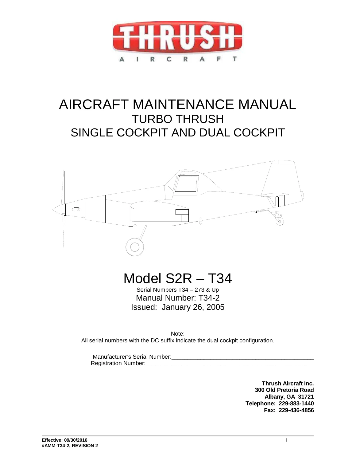
Thrush S2R-T34 Turbo Thrush Aircraft Maintenance Manual AMM-T34-2 Revision 2
Original price was: $39.95.$24.95Current price is: $24.95.
Official factory Aircraft Maintenance Manual for the Thrush S2R-T34 Turbo Thrush (Serial Numbers T34-273 & Up), covering single and dual cockpit configurations equipped with Pratt & Whitney Canada PT6A-34AG turboprop engines.
Description
Complete Factory Technical Service Authority: Thrush S2R-T34 Turbo Thrush Aircraft Maintenance Manual AMM-T34-2 Revision 2
The Thrush S2R-T34 Turbo Thrush Aircraft Maintenance Manual AMM-T34-2 Revision 2 provides complete airframe, mechanical, structural, and electrical maintenance instructions for both Single Cockpit and Dual Cockpit (DC) agricultural aircraft across serial numbers T34-273 and subsequent. Formatted in accordance with standard ATA specifications and incorporating FAA Project AT10792AT-A for 10,500 lbs maximum gross takeoff weight (GTOWT) certification, this manual is the essential technical reference for licensed aircraft mechanics, agricultural aviation fleet managers, and owner-operators dedicated to maintaining structural integrity and peak operating safety.
File Details
- Manual Type: Aircraft Maintenance Manual (AMM)
- Brand: Thrush Aircraft, Inc.
- Model Coverage: Model S2R-T34 Turbo Thrush (Single Cockpit & Dual Cockpit configurations)
- Serial Effectivity: Serial Numbers T34-273 and Subsequent (including all DC suffix dual cockpit aircraft)
- Engine Installation: Pratt & Whitney Canada PT6A-34AG Turboprop
- Manual Number: T34-2 (#AMM-T34-2)
- Revision & Date: Revision 2, Effective September 30, 2016 (FAA Accepted February 13, 2017)
- Document Format: High-Resolution Searchable PDF Document
- Page Count: 537 Pages
- Language: English
Airworthiness Limitations & Scheduled Inspection Protocols
Airworthiness compliance under 14 CFR § 43.16 and § 91.403 requires rigid adherence to the factory structural lifing and inspection schedules detailed in this publication. The Thrush S2R-T34 Turbo Thrush Aircraft Maintenance Manual AMM-T34-2 Revision 2 establishes mandatory life-limited thresholds, including a 29,000-flight-hour retirement life on the Left-Hand (P/N 22507T001) and Right-Hand (P/N 22507T002) lower spar cap assemblies. It mandates strict 1,500-hour life limits on tail-wheel spring P/N 5079-1 for operations subject to repetitive ground-air-ground cycles or rough-field operations (extended to 3,000 hours for paved operations, with an absolute mandatory replacement at 5,000 hours). Lower spar splice blocks (upper half P/N 22508T001 and lower half P/N 22508T002) require annual non-destructive visual checks utilizing 10X magnification or liquid dye penetrant inspection across the 1/4-inch and 5/16-inch fastener holes.
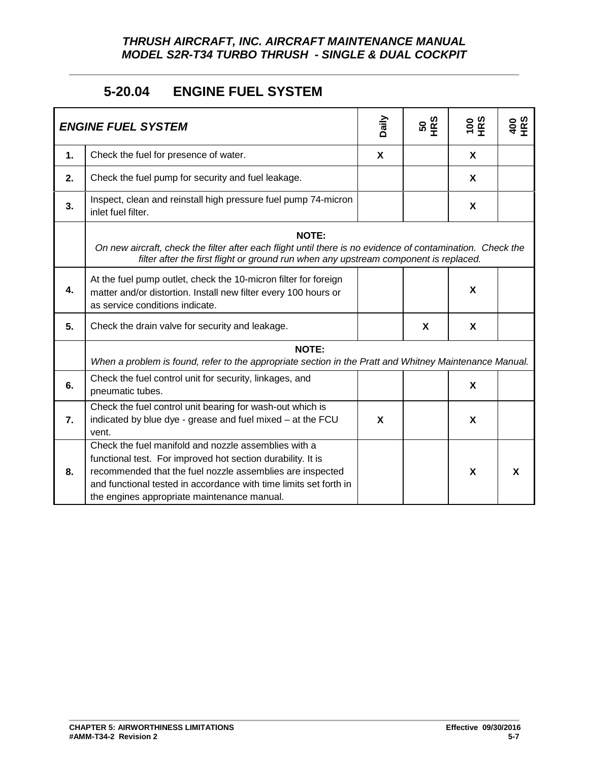
Comprehensive time limits structure scheduled check intervals into Daily, 50-hour, 100-hour, and 400-hour increments. Critical inspection items encompass:
- Propeller & Governor Checks: Daily blade inspections for nicks and cracks, Hartzell overspeed governor checks, reverse return spring integrity, and 100-hour lubrication using exclusively AeroShell 6 grease. Includes beta control valve clevis alignment and low pitch stop collar run-out limits (0.010 in maximum).
- Engine Externals & Induction: 100-hour checks for Pratt & Whitney Canada PT6A-34AG engine mounts, exhaust duct distortion, pneumatic P3 compressor delivery filters, starter-generator brush wear, and starter drive gear spline inspection (distinguishing pre-1998 dry splines requiring Dow Corning M-77 Molykote paste from wet-spline configurations).
- Landing Gear Hardware: 800-hour and annual non-destructive inspections of main landing gear attach bolts (P/N AN10-33 or NAS6610D42), with mandatory replacement every 1,600 hours or biannually, coupled with AeroShell 22 lubrication of knurled bushings.
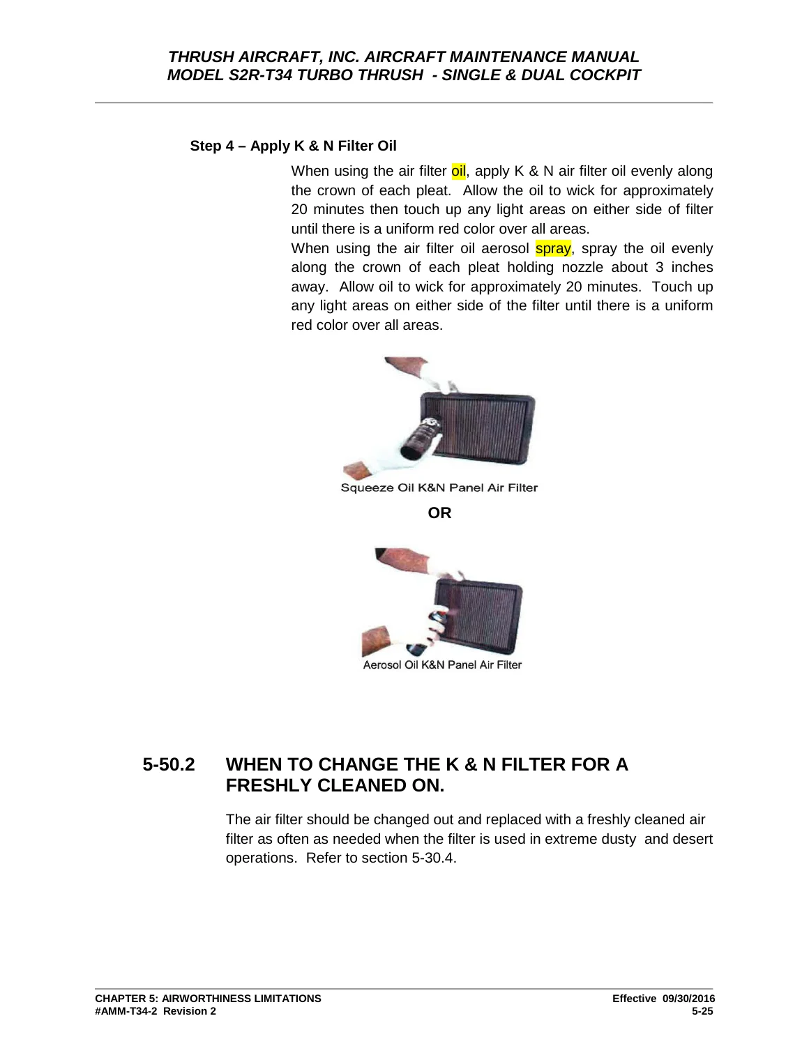
- Air Filter Servicing: Clear criteria for washing and re-oiling reusable K&N engine air intake barrier filters using low-pressure backflushing, natural air drying without compressed air, and uniform oil re-application across pleats.
Flight Control Rigging & Surface Alignment
Precise aerodynamic alignment and control harmony are engineered through factory push-pull tubes, bellcranks, idlers, and balance cable circuits. The Thrush S2R-T34 Turbo Thrush Aircraft Maintenance Manual AMM-T34-2 Revision 2 gives exact angular travels and mechanical tolerances:
- Aileron System: Travel limits set at 21 degrees (±1°) UP and 17 degrees (±1°) DOWN. In neutral position, ailerons must align exactly 1/8 inch (0.125 in) below the wing flap trailing edge. Details pushrod adjustments to keep inboard bellcranks perpendicular to the rear spar, torque tube bolt torques (65 to 70 in-lbs), and balance spring tensioning in the rudder-aileron interconnect.
- Wing Flaps: Electrically driven jackscrew mechanism with microswitches calibrated for 15 degrees (±1°) full DOWN travel, verified using a propeller protractor, with mechanical travel stops adjusted to maintain a 0.060 to 0.100 inch clearance to the stop pad.
- Rudder & Empennage: Rudder deflection set at 24 degrees (±1°) LEFT and RIGHT against adjustable stop bolts at the rudder post base. Rudder pedals adjusted to 11.00 inches from the hopper aft wall at station 175.12, safety wired with 0.041 stainless steel wire.
- Elevator & Trim Tabs: Primary elevator deflection calibrated for 27 degrees (±1°) UP and 17 degrees (±1°) DOWN, with control stick stops positioned 7.00 inches from the hopper face at full forward throw. Elevator trim tab travel is adjusted to 8 degrees (±1°) UP and 22 degrees (±1°) DOWN, with pushrod free-play capped at a maximum of 0.125 inch.
- Horizontal Stabilizer Incidence: Longitudinal leveling and horizontal stabilizer chord line alignment set to -0.50 degrees (±0.25°) nose-down relative to the cockpit leveling longeron, using calibrated attach bushings and AN960-616 washers torqued to 408 ± 15 in-lbs.
Fuel System Architecture, Sealing & Indicating
Fuel management instructions encompass the total 230 U.S. gallon capacity distributed across integral wet-wing tanks (extending between WS 26.940 and WS 103.506) and the central 5 U.S. gallon fuselage header tank. Technicians are provided with complete maintenance procedures for the 25-micron gascolator main fuel filter, 1/4-inch header tank finger screen, auxiliary fuel boost pump (supplying 20 ± 1 psi for starting and emergency backup), and the 3-shutdown residue fuel reservoir (EPA tank).
Structural tank sealing protocols govern the application of fuel-resistant polysulfide sealants meeting AMS-S-8802 (CS 3204 Class A2 brushable and Class B2 thixotropic paste), joint preparation with MEK or acetone, faying surface thicknesses (0.015 inch), and CS 3600 topcoating. Instructions include water-manometer pneumatic leak check methods at pressures between 38 and 44 inches of water (1.589 psi maximum) with a 5-minute leak-down rate not exceeding 0.25 inch. Indicating calibration covers both traditional analog round gauges and the digital MVP-50T Glass Engine Monitor interfaced via the RFLM-4-24 resistive fuel level module, detailing empty, 14-gallon, 28-gallon, 55-gallon, and 82-gallon unmetered cutoff thresholds.
Electrical Distribution, Generation & System Avionics
The manual details electrical maintenance across distinct production serial blocks. For aircraft serial numbers T34-273 through T34-408, the 28-volt DC system utilizes an analog voltage regulator adjusted under no-load to 26.5 ± 0.2 VDC and a reverse current relay (RCR) set for 27.5 VDC bus operation. Aircraft T34-409 and subsequent feature an advanced solid-state Generator Control Unit (GCU) and Line Contactor Relay, providing automatic starter cutout, line voltage matching, and overvoltage shutdown at 32 VDC.
Technicians have direct access to wiring schematics and quick-disconnect connector pinouts (connectors QDA, QDB, QDC, QDD, QDE, QDF, QDG, QDH, QDJ, QDL, QDM, QDN, QDP, and QDR), dual 24-volt battery maintenance and specific gravity benchmarks (1.285 to 1.295 charged, 1.275 recharge point), APU external power connections, starter-generator troubleshooting, air conditioning and blower schematics, and P3 fuel control pneumatic line heater circuitry.
Chapters Covered
- Chapter 5: Time Limits / Maintenance Checks — Airworthiness limitations, structural life limits, scheduled maintenance tables (daily, 50, 100, 400 hr), extreme cold and hot desert operating precautions, aircraft washing, and K&N air filter cleaning procedures.
- Chapter 6: Dimensions and Areas — General airframe dimensions (47.50 ft wingspan, 32.71 ft length, 11.42 ft height, 9.00 ft tread), wing stations, fuselage stations, water lines, butt lines, control surface areas, and 3-view engineering drawings.
- Chapter 7: Lifting & Shoring — Airframe jacking procedures, main spar jack points at WS 120.00 and WS 193.38, and tailwheel lower longeron jacking points.
- Chapter 8: Leveling & Weighing — Longeron leveling methods under the cockpit and flight manual weight and balance references.
- Chapter 9: Towing & Taxiing — Ground handling, tow bar attachments, beta mode taxiing limits, and propeller FOD precautions.
- Chapter 10: Parking, Mooring, Storage & Return to Service — Parking brake limitations, wind tie-down knots, and gust velocity moorings up to 50 knots.
- Chapter 11: Placards and Markings — Flight manual exterior and interior placard location references.
- Chapter 12: Servicing — Engine oil replenishment (PT6A dipstick calibrations and hot/cold checks), approved turbine fuels (Jet A, B, JP-4, JP-5, diesel, avgas limits), tire pressure specs (main gear 40–62 psi, tailwheel 88 psi), landing gear shock strut biscuit servicing, 8-sheet comprehensive lubrication charts, and dry motoring engine fire clearance procedures.
- Chapter 21: Air Conditioning — Optional Zee air conditioning and heating system layout, compressor and condenser mounting, evaporator servicing, and single/dual cockpit schematics.
- Chapter 24: Electrical Power — 300A starter-generator, battery care, voltage regulator removal/adjustment, GCU installation, APU power distribution, troubleshooting charts, and detailed connector wiring pinouts (QDA through QDR).
- Chapter 26: Fire Protection — Cockpit fire extinguisher options and maintenance check placards.
- Chapter 27: Flight Controls — Control stick assembly, bearing replacement, aileron rigging, rudder cables, elevator push tubes, horizontal stabilizer incidence, flap jackscrew microswitches, troubleshooting tables, and internal/external gust locks.
- Chapter 28: Fuel System — Integral wet-wing tank resealing, pressure checks, fuel vent manifold, auxiliary vane pump, Airborne 1J18 filter disassembly, finger screens, and fuel transmitter calibration for round gauges and MVP-50T glass cockpit.
- Chapter 31: Indicating/Recording Systems — Forward and rear cockpit instrument panels, analog round gauges vs. Electronics International MVP-50T turboprop monitor installations, instrument removal, and system troubleshooting charts.
Together, these technical chapters provide an exhaustive, practical foundation for maintaining the Thrush S2R-T34, arming aviation technicians with verified engineering tolerances, wiring details, and structural inspection procedures directly from the manufacturer.
Professional Maintenance Authority & Instant Delivery
Eliminate guesswork and ensure complete airworthiness compliance during every 100-hour inspection, annual review, or field overhaul with the Thrush S2R-T34 Turbo Thrush Aircraft Maintenance Manual AMM-T34-2 Revision 2. By following genuine factory procedures, exact torque values, and certified rigging specifications, maintenance personnel protect vital airframe life limits, maintain engine reliability, and guarantee safe operational performance. Available as an instant digital PDF download immediately upon checkout, this manual allows you to access crucial technical schematics on your laptop, tablet, or mobile device in the hangar or print clean, full-scale work pages for the shop floor.
Reviews
There are no reviews yet.