
Pratt & Whitney Canada PT6A Engine Overhaul Manual – Chapter 72-30 Compressor (Part No. 3021243)
Original price was: $39.95.$24.95Current price is: $24.95.
Factory overhaul manual for Pratt & Whitney Canada PT6A series turboprop engines covering Chapter 72-30 Compressor, including gas generator assembly, fireseals, wash ring, gas generator case, and compressor rotor disassembly, inspection, repair, sub-assembly, fits, and clearances.
Description
Pratt & Whitney Canada PT6A Engine Overhaul Manual – Chapter 72-30 Compressor (Part No. 3021243)
The Pratt & Whitney Canada PT6A Engine Overhaul Manual – Chapter 72-30 Compressor (Part No. 3021243) is the official technical standard for workshop overhaul, maintenance engineering, and depot-level rebuilding of the compressor and gas generator section on PT6A turboprop engines. Published by Pratt & Whitney Canada, this comprehensive overhaul manual provides authorized step-by-step instructions, precision dimensions, non-destructive testing requirements, protective recoating processes, machining parameters, and assembly procedures. Covering the gas generator assembly, center and rear fireseals, compressor wash spray ring, gas generator case, and compressor rotor assembly, this document delivers the exact manufacturing and overhaul limits required to return critical engine components to airworthy condition.
File Details
- Manual Type: Engine Overhaul Manual (Chapter 72-30 Compressor)
- Manufacturer: Pratt & Whitney Canada
- Manual Part Number: 3021243
- Publication / Revision Date: October 09, 2017
- Language: English
- Page Count: 560 Pages
- Document File Format: Adobe PDF (Digital Download)
- Applicable Engine Models: PT6A-34, PT6A-34AG, PT6A-34B, PT6A-35, PT6A-36, PT6A-114, PT6A-114A, PT6A-116, PT6A-135, and PT6A-135A
Chapters Covered
- 72-30-00 Gas Generator Assembly
- Description and Operation
- Disassembly (Breakdown, Manifold Adapters, Drain Valves, Combustion Liner, Compressor Turbine, Shroud Housing, Bleed Case, Bleed Valve, Inlet Case, No. 1 Bearing, Compressor Rotor)
- Cleaning (Sub-assembly Cross References)
- Inspection (Sub-assembly Cross References)
- Repair (Component Processing Guidelines)
- Sub-Assembly (Stand Installation, Impeller Axial Clearance Setup, No. 1 and No. 2 Bearing Build, Inlet Case, Shroud Grinding, Turbine Installation, Fuel Manifolds, Drain and Bleed Valves)
- Fits and Clearances (Table 601 Reference Fits, Table 602 Torque and Stretch, Table 604 Special Assembly)
- Storage Instructions (Preparation, Preservation, Sealing)
- Light Overhaul (Reference Guide to Section 72-00-00)
- 72-30-01 Center Fireseal
- Description and Operation
- Disassembly (Mounting Ring Separation)
- Cleaning (SPOP 209 Processing)
- Inspection (Mounting Ring Damage, Packing Material, Safety Wire Lugs, Angle Brackets)
- Repair (Sealing Strip Replacement, Adhesive Bonding, Lockwire Lug Weld Repairs)
- Sub-Assembly (Integration with Engine Build)
- Fits and Clearances
- Storage Instructions (Flexibility Protection, Packaging)
- Light Overhaul
- 72-30-02 Rear Fireseal and Wash Ring
- Description and Operation
- Disassembly (Plug and Rivet Removal)
- Cleaning (SPOP 209, Solvent Flushing of Spray Tubes)
- Inspection (Tubing Integrity, Coupling Threads, Spray Orifice Dimensions, Bracket Cracks)
- Repair (Insulating Strip and Rubber Cushion Bonding, Bracket Crack Weld Repair, Lockwire Lug Replacement)
- Sub-Assembly (Plug and Preformed Packing Installation, Flaring)
- Fits and Clearances
- Storage Instructions (Masking, Packaging, Preservation)
- Light Overhaul
- 72-30-04 Gas Generator Case
- Description and Operation
- Disassembly (Air Bleed and Outlet Covers, Oil Nozzle Strainer, Fire Seals and Vane Segments Post-SB1445)
- Cleaning (Degreasing, SPOP 209/203, Paint Stripping SPOP 213/258, Contaminated Oil System Power Flush, Solvent Pressure Flushing)
- Inspection (Mandatory Overhaul Checks, Air and Hydraulic Pressure Testing, Fluorescent Penetrant Inspection SPOP 62, P3 Metering Holes, Dimensional Checks, Crack Limits for Bosses, Port Holes, and Flanges)
- Repair (Method A Air Pressure Test, Method B Hydraulic Pressure Test, Protective Coating Application: SermeTel W PWA 110-2, Alseal 518 PWA 110-21, SermeTel 5380DP, Ceral 3450; Helical Insert and Keensert Installation, Diffuser Entry Burnishing, Straightening Vane Replacement, Diffuser Exit Duct Rework, Rivet Hole and Fretting Repair)
- Sub-Assembly (No. 2 Bearing Oil Nozzle Assembly, Flow Testing, Air Bleed Covers, Fire Seal and Vane Installation)
- Fits and Clearances
- Storage Instructions
- Light Overhaul (Overtemperature, Sudden Stoppage, Oil Contamination, Overspeed, Water Immersion, Fire Extinguisher Contamination)
- 72-30-05 Compressor Rotor
- Description and Operation
- Disassembly (Rotor Breakdown, Rear Hub Teardown)
- Cleaning (Antifriction Bearings, Tie Rods, Disks, Spacers, Impeller, Stators, Housing Coatings)
- Inspection (Compressor Air Seals, Tie Rods, Stubshaft, Impeller, Stators, Compressor Blades, Rear Hub, Spanner Nuts, Adapters)
- Repair (Protective Coating Restoration, Rear Hub Journal Nickel-Plating and Plasma Spray, Tie Rods, Stator Vanes, Snap Diameters, Blade Blending)
- Sub-Assembly (Centrifugal Impeller Dynamic Balancing, Front Stubshaft Buildup, Rear Hub Assembly, Nos. 1 and 2 Bearing Buildup, Rotor Assembly Dynamic Balancing)
- Fits and Clearances
- Storage Instructions
- Light Overhaul (Overspeed Limits: Ng Exceeded 102.6%, 106%, 110%, 111%; Sudden Stoppage, Water Immersion, Unusual Oil Conditions)
Together, these technical chapters provide an end-to-end operational blueprint for the PT6A compressor section. Technicians and overhaul engineers gain precise, step-by-step instructions for breaking down major modules into sub-assemblies, executing non-destructive testing (NDT), repairing localized damage to parent materials, replacing life-limited wear items, establishing factory axial clearances, and executing dynamic balancing before final build.
Gas Generator Teardown & Sub-Assembly Procedures (72-30-00)
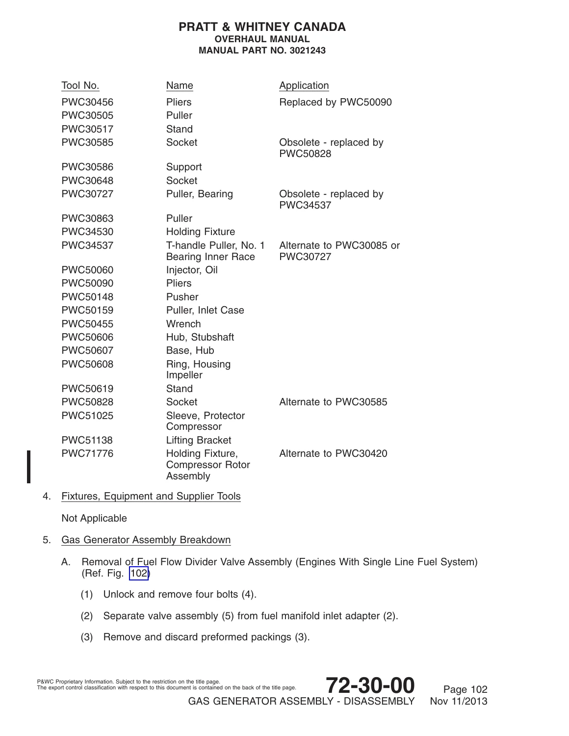
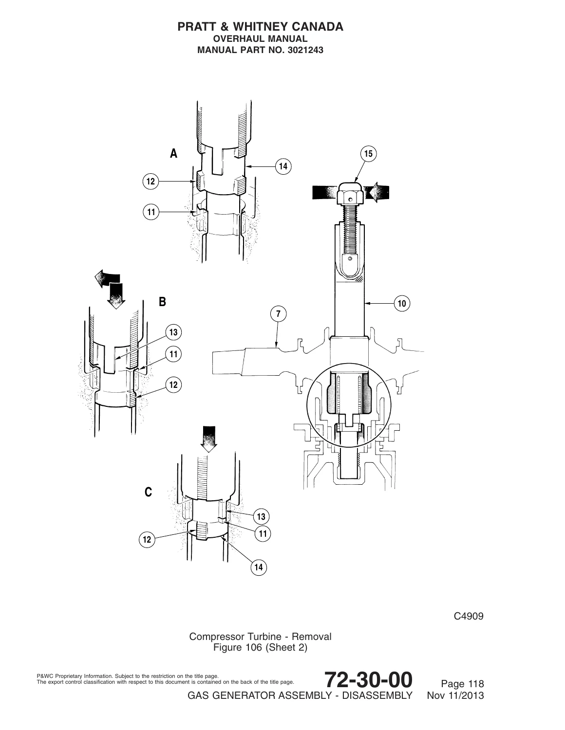
The general disassembly section of Chapter 72-30-00 guides the technician through the complete strip-down of the gas generator module once separated from the power section and accessory gearbox. Specific disassembly operations cover the fuel flow divider valve removal on single-line fuel systems, fuel manifold and nozzle assembly extraction (including Pre-SB1511 bolt retention and Post-SB1511 stud/nut configurations on PT6A-114/114A engines), front and rear drain valve removals, spark igniters/glow plugs extraction, and withdrawal of the combustion chamber liner from the gas generator case. The manual details the specific extraction of the compressor turbine bladed disk using special wrench PWC30335/PWC30331, spreader, and puller PWC30403, preventing damage to the turbine blades and shroud segments during removal.
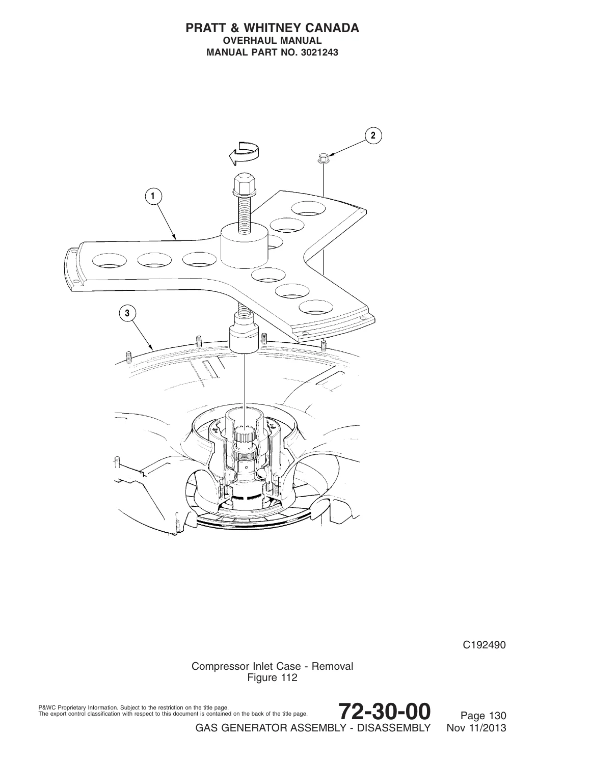
Subsequent disassembly steps detail the removal of the compressor turbine vane ring, shroud housing, small exit duct, and No. 2 bearing housing cover using puller PWC30863; removal of the bleed air case and air inlet screens; separation of the compressor bleed valve; and removal of the compressor inlet case using pusher PWC50148 and puller PWC50159. Teardown of the No. 1 bearing assembly is thoroughly detailed, specifying spanner nut removal with socket PWC30585 or PWC50828, and inner race pulling with pullers PWC30085, PWC30727, or PWC34537. Compressor rotor extraction from the case is performed using specialized puller PWC30505 resting on flange F.
The sub-assembly instructions present exacting procedures for rebuilding the gas generator assembly. A central focus is establishing the precise axial running clearance between the centrifugal impeller and the impeller housing (Ref. No. 317 in Fits and Clearances). This is accomplished through precision dimensional measurement using measuring bar PWC34456 across inlet casing flange F with a depth micrometer to determine Dimension A (datum to inner race) and Dimension B (datum to rear rotor air seal). Technicians calculate the required thickness of the No. 1 bearing adjusting spacer using the factory formula: A + B – (2 x D) + C = T, where D is the bar datum-to-slide foot dimension and C is the specified mean axial clearance. The manual provides explicit instructions for grinding the rear face of the spacer to within 0.0002 inch flatness and parallelism with a 63AA surface finish, followed by de-magnetization. Procedures also mandate dry-ice cooling of the compressor hub using holder PWC50826 and oven heating of No. 1 bearing inner races to 141-149°C (285-300°F) prior to installation with installer PWC71673.
Further critical build procedures include measuring compressor turbine shroud segment diameter using radius gage PWC71568 and grinding shroud segments to exact finished dimensions using pneumatic grinder PWC37918 and grinding wheels PWC32528/PWC32588 to achieve the required 0.012 to 0.015 inch radial blade tip clearance. The document also instructs technicians on calculating and selecting the correct compressor turbine rotor air seal class (Classes CL1 through CL7) to maintain the required 0.050 to 0.060 inch axial running clearance between the compressor turbine disk and vane ring.
Gas Generator Case Inspection, Protective Coatings & Overhaul (72-30-04)
Chapter 72-30-04 provides complete instructions for reconditioning the structural gas generator case. Mandatory overhaul inspection includes cleaning, pressure testing, fluorescent penetrant inspection (SPOP 62), dimensional checks, and P3 metering hole verification. Pressure testing procedures offer two distinct methodologies: Method A pneumatic immersion testing at 65° to 87°C (150° to 190°F) using 25-30 psig for pressure oil and sensing tubes and 10-20 psig for scavenge tubes and the case vessel; or Method B hydraulic pressure testing using 20% fluorescent penetrant oil in mineral oil at 250-275 psig for pressure oil passages and 50-55 psig for scavenge passages.
Protective coating maintenance is covered in detail, including degreasing and paint stripping (SPOP 213 or abrasive blasting per SPOP 9), followed by reapplication processes: Method A applying PWA 595-1 (SermeTel type W) per PWA 110-2; Method B applying PWA 595-2 (Alseal 518) base and PWA 561-2 top coat per PWA 110-21; Method C application of SermeTel 5380DP; Method D application of Ceral 3450; or diffused aluminide pack coating (Chromalloy A-12 / CPW 58). Specific masking instructions and coating thickness limits (0.0008 to 0.0015 inch in designated areas; 0.0015 to 0.0025 inch general thickness) are enforced. The manual details P3 metering hole requirements at the No. 2 bearing housing, providing a comprehensive table of hole diameters (0.092 to 0.099 inch) and specifying which seven holes must be plugged with rivet P/N 3023074 across various case part numbers.
Weld repairs and crack limitations are thoroughly documented. Permissible crack thresholds are defined for fusion welds, external bosses (igniter, drain, bleed, and oil bosses limited to 25% of weld length or 1.000 inch), fuel nozzle bosses (0.500 inch max crack in fillet radius), port holes, and flange joint welds. The repair section details boss thread repair using Keensert and helical coil inserts, flange distortion correction (up to 0.060 inch cold work), diffuser entry burnishing, diffuser exit duct re-gapping and replacement (brazed and clamp-on styles), and bleed case support ring rivet hole elongation and fretting wear repairs.
Critical Fits, Clearances & Factory Torque Specifications
Section 72-30-00 Table 601 and Table 602 contain the mandatory assembly tolerances, wear limits, and torque settings essential for ensuring proper aerodynamic performance and mechanical reliability across all PT6A variants:
- Ref. 253 – Compressor Turbine Rotor Air Seal to Stator: Radial clearance 0.0050 to 0.0055 in. (rotor air seal OD 2.1195 to 2.1200 in.; stator air seal ID 2.1300 to 2.1305 in.).
- Ref. 256 – No. 2 Bearing Roller Flanged to Gas Generator Case: Fit limit 0.0002 Tight to 0.0015 in. (bearing OD 2.6769 to 2.6772 in.; case bore 2.6770 to 2.6784 in.).
- Ref. 260 – Vane Ring Lock Plate to No. 2 Bearing Housing Cover: Clearance 0.005 to 0.015 in. (lock plate ID 5.309 to 5.313 in.; cover OD 5.298 to 5.304 in.).
- Ref. 265 – Compressor Rotor Air Seal to Stator: Radial clearance 0.0060 to 0.0065 in. (rotor seal OD 2.4495 to 2.4500 in.; stator seal ID 2.4620 to 2.4625 in.).
- Ref. 298 – Compressor Rear Rotor Air Seal to Rear Stator Air Seal: Radial clearance 0.0060 to 0.0075 in. (rotor seal OD 1.900 to 1.901 in.; stator seal ID 1.913 to 1.915 in.).
- Ref. 301 – Compressor Inlet Case to Gas Generator Case: Interference fit 0.0100 Tight to 0.0020 Tight (inlet case OD 11.1310 to 11.1340 in.; case bore 11.1240 to 11.1290 in., after coating).
- Ref. 308 – Compressor Rear Hub to No. 1 Bearing Inner Race: Fit 0.0001 Tight to 0.0008 Tight (hub OD 1.1812 to 1.1817 in.; inner race bore 1.1809 to 1.1811 in.; replace at 0.0000).
- Ref. 316 – Compressor Turbine Disk to Turbine Vane Ring: Axial running clearance 0.050 to 0.060 in.
- Ref. 317 – Centrifugal Impeller to Housing: Axial clearance 0.027 to 0.029 in.
- Ref. 318 – Compressor Turbine Blade Radial Tip Clearance: 0.012 to 0.015 in. with new shroud segments; 0.010 to 0.017 in. with run segments (measured at trailing edge with feeler gages).
- Ref. 489 – Compressor Turbine Vane Ring End Float: 0.000 to 0.005 in. end float against No. 2 bearing cover.
- Ref. 541 – Compressor Turbine Stubshaft Bolt Torque: Pre-SB1439: 420 to 460 lb.in.; Post-SB1439 and PT6A-35: 500 to 550 lb.in. (torque initially to 600 to 650 lb.in., relax to zero, then apply final torque; max loosening torque 1800 lb.in.).
- Ref. 544 – No. 1 Bearing Spanner Nut Torque: 1,100 to 1,300 lb.in. (torque to limits, relax to zero, retorque to limits).
- Ref. 545 – No. 1 Bearing Outer Race Ring Nut Torque: 1,000 lb.in. (torque to limits, relax to zero, retorque or advance to locking position without exceeding 4,000 lb.in.).
- Ref. 562 – Ignition Hardware Torque: Glow plugs (Pre-SB1196 & PT6A-34B) 300 to 360 lbf.in.; Spark igniters (Post-SB1196 & PT6A-34AG/-34B/-35/-114/-114A/-135/-135A) 200 to 240 lbf.in. into dry bosses.
- Ref. 957 – Gas Generator Drain Valve Adapters: 450 to 550 lb.in.
Center Fireseal, Rear Fireseal & Compressor Wash Ring Maintenance (72-30-01 & 72-30-02)
Dedicated sections cover the center fireseal (72-30-01) and rear fireseal with compressor wash ring (72-30-02). Cleaning procedures specify SPOP 209 degreasing, while inspection routines address mounting ring distortion, chafing, cracking around mounting holes, and safety wire lug condition. Sealing strip replacement is detailed using solvent cleaning (PWC11-014), surface roughening with abrasive cloth (PWC05-014), and bonding with fluorosilicone adhesive (PWC08-002) or rubber cement (PWC08-010) and silicone rubber sealant (PWC09-001/PWC09-001A), allowing 72 hours for full bond strength. Damaged lockwire lugs are restored by grinding old welds, swabbing with ethyl alcohol (PWC11-009), and spot-welding or plug-welding replacement lugs using filler rod PWC05-216A. Compressor wash ring servicing covers tubular rivet removal with a 3/32-inch drill, spray ring tube flushing, spray orifice inspection (0.057 inch diameter), and bracket crack welding using AMS 5680 or AMS 5786 filler wire followed by fluorescent penetrant inspection (SPOP 62).
Essential Specialized Tooling & Workshop Fixtures
Accurate execution of PT6A compressor overhaul requires specialized service tooling detailed throughout this manual. Key tools specified include:
- Holding Fixtures & Stands: Compressor rotor assembly holding fixtures PWC30420 and PWC71776; engine overhaul stands PWC30455, PWC30517, PWC30800, and PWC50619; rotor base hub PWC50607, stubshaft hub PWC50606, and housing ring PWC50608; bearing holding fixture PWC71016.
- Pullers & Extractors: Compressor turbine puller PWC30403; compressor rotor extractor puller PWC30505; No. 1 bearing inner race pullers PWC30085, PWC30727, and PWC34537; No. 2 bearing housing cover puller PWC30863; compressor inlet case puller PWC50159 with coupling nut; pusher PWC50148.
- Wrenches & Sockets: Flange wrenches PWC30114-02 and PWC30114-15; bearing spanner nut sockets PWC30115, PWC30585, PWC30648, and PWC50828; compressor turbine holding wrench PWC30331 and spreader PWC30335; impeller clearance bridge loading wrench PWC50455 with spacer PWC50473.
- Measuring, Grinding & Assembly: Inlet casing measuring bar PWC34456 (and PWC32056); compressor rotor alignment fixture PWC30452 and spigot PWC30370; No. 1 bearing loading fixture PWC30441; radius gage PWC71568 with dial indicator and master; pneumatic turbine shroud grinder PWC37918 with diamond dresser PWC37917 and grinding wheels PWC32528/PWC32588; bearing installer PWC71673 with split grip and closing ring; dry ice holder PWC50826; keywasher squeezer PWC30458; retaining ring pliers PWC30456 and PWC50090; cupwasher crimper PWC64035, PWC65658, and pliers PWC50925-1.
Comprehensive Overhaul Capability, Compliance & Instant PDF Delivery
The Pratt & Whitney Canada PT6A Engine Overhaul Manual – Chapter 72-30 Compressor (Part No. 3021243) equips maintenance facilities, licensed A&P mechanics, and gas turbine technicians with complete technical capability to overhaul the PT6A compressor section to precise factory standards. Utilizing authorized Pratt & Whitney Canada procedures guarantees absolute airworthiness compliance, ensures optimal compressor pressure ratios and turbine blade tip clearances, eliminates operational vibration, and preserves the service life of high-energy rotating assemblies. Delivered as an instant, high-clarity PDF download immediately upon checkout, this document eliminates shipping wait times, allows seamless navigation across desktop, tablet, and mobile devices in the overhaul shop, and supports complete full-size printing of detailed engineering diagrams, clearance charts, and overhaul worksheets.

Reviews
There are no reviews yet.