★ TRUSTED BY 321,897+ PROFESSIONALS WORLDWIDE
🏢
Trusted Business
Verified & Licensed
🛡️
Virus Free Files
100% Safe Downloads
🔒
Secure Payment
SSL Protected
Instant Delivery
Available Immediately
Sale!

Sikorsky UH-60A UH-60L EH-60A HH-60A HH-60L Aviation Unit and Intermediate Maintenance Manual TM 1-1520-237-23-3 Volume 3 (2014) – PDF Download

Original price was: $49.95.Current price is: $29.95.

Official U.S. Army aviation unit and intermediate maintenance manual TM 1-1520-237-23-3 Volume 3 for Sikorsky UH-60A, UH-60L, EH-60A, HH-60A and HH-60L helicopters, dated 30 May 2014. Covers AC/DC electrical systems, fuel systems, flight controls and related troubleshooting procedures with wiring and schematic diagrams.

Instant PDF Download
Available immediately
💾
Save to Your Device
Download & keep forever
🛡️
Antivirus Scanned
100% virus-free
🌍
Trusted Worldwide
175,000+ customers

Description

Sikorsky UH-60A UH-60L EH-60A HH-60A HH-60L Aviation Unit and Intermediate Maintenance Manual TM 1-1520-237-23-3 Volume 3

This is the third volume of the U.S. Army aviation unit and intermediate maintenance technical manual covering the Sikorsky UH-60A, UH-60L, EH-60A, HH-60A and HH-60L utility tactical transport helicopters. Volume 3 is built around the chapter-3 troubleshooting procedures, electrical systems, fuel systems and mechanical flight controls, and it carries the full complement of operational checkout tests, corrective action paths, schematic diagrams and location diagrams needed to isolate and fix faults on these aircraft.

The document is written for MOS 15F aircraft electricians and MOS 15T UH-60 helicopter repairers working at the aviation unit (AVUM) and intermediate (AVIM) maintenance levels, and it is equally useful to any owner, operator or maintainer of a UH-60-series airframe who needs the genuine troubleshooting logic, test-point values and wiring references for the aircraft’s major systems.

File Details

  • Manual type: Aviation unit and intermediate maintenance technical manual (AVUM/AVIM)
  • Document number: TM 1-1520-237-23-3
  • Volume: Volume 3
  • Date of issue: 30 May 2014
  • Issuing authority: Headquarters, Department of the Army
  • Brand / manufacturer: Sikorsky
  • Models covered: UH-60A, UH-60L, EH-60A, HH-60A, HH-60L
  • Language: English
  • File format: PDF

Chapters and Work Packages Covered

The active portion of this volume is Chapter 3 – Aviation Unit and Intermediate Troubleshooting Procedures. The troubleshooting work packages, listed in the manual’s table of contents, include:

  • AC Electrical System (WP 0105 00)
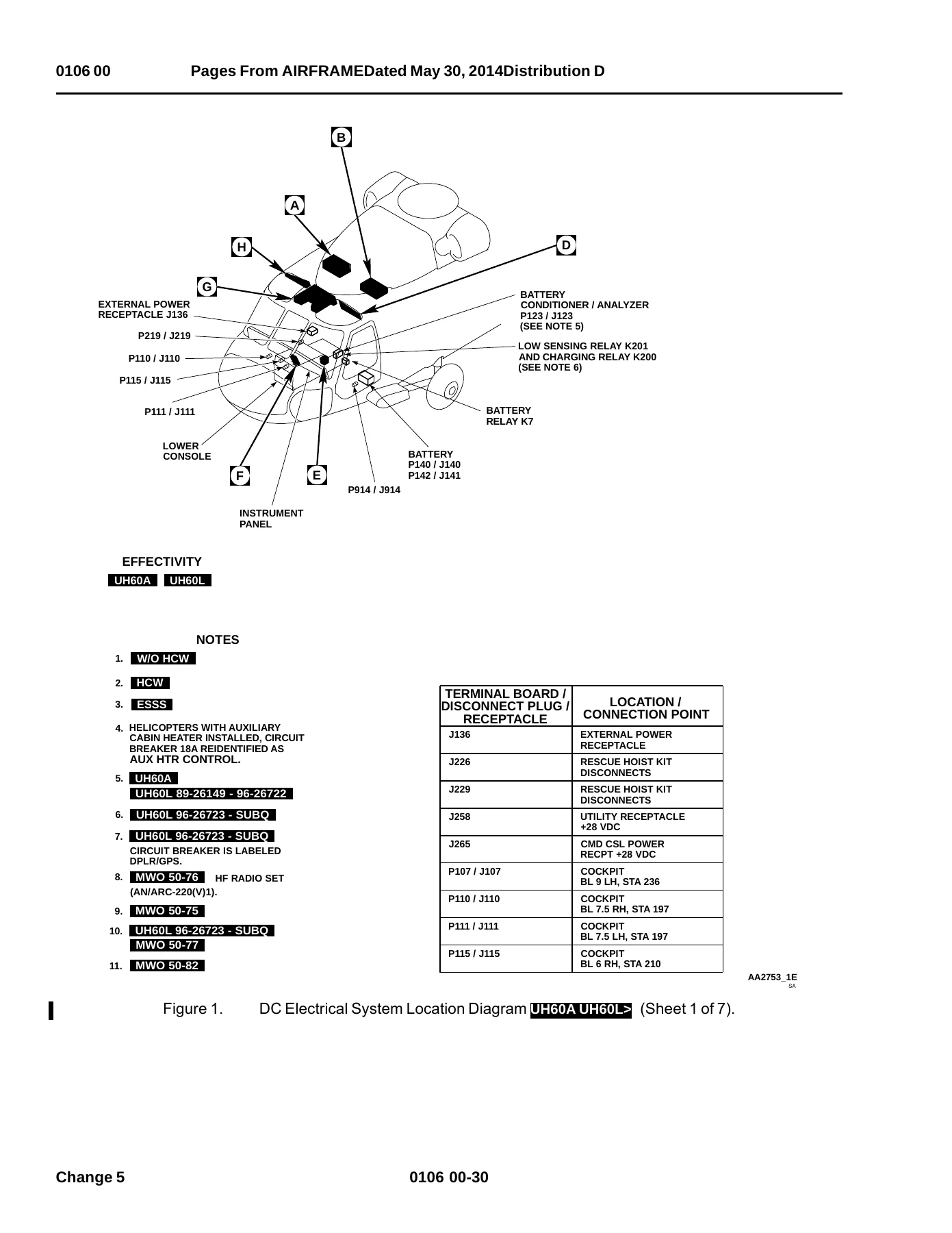
  • DC Electrical System (WP 0106 00)
  • Mission Electrical Interface EH-60A (WP 0107 00)
  • System Circuit Breakers (WP 0108 00)
  • Instrument Panel Lights (WP 0109 00)
  • Upper and Lower Console Lights (WP 0110 00)
  • Cabin Dome Lights (WP 0111 00)
  • Cockpit Flood and Secondary Lights (WP 0112 00)
  • Utility and Maintenance Lights (WP 0113 00)
  • Instrument Panel and Consoles Indicator Lights Dimming (WP 0114 00)
  • Formation Lights (WP 0115 00)
  • Controllable Searchlight (WP 0116 00)
  • Position Lights (WP 0117 00)
  • Retractable Landing Light (WP 0118 00)
  • Anti-collision Lights (WP 0119 00)
  • Cargo Hook Lights (WP 0120 00)
  • ECM Antenna Actuator Assembly EH-60A (WP 0121 00)
  • Fuel Boost Pump Control Panel (AVIM) (WP 0122 00)
  • ECM Antenna Actuator Assembly (AVIM) EH-60A (WP 0123 00)
  • Right Hand Relay Panel (AVIM) (WP 0124 00)
  • Left Hand Relay Panel (AVIM) (WP 0125 00)
  • AC Electrical System HH-60A/HH-60L (WP 0126 00)
  • DC Electrical System HH-60A/HH-60L (WP 0127 00)
  • Upper and Lower Console Lights HH-60A/HH-60L (WP 0128 00)
  • Instrument Panel Lights HH-60A/HH-60L (WP 0129 00)
  • Instrument Panel and Consoles Indicator Lights Dimming HH-60A/HH-60L (WP 0130 00)
  • Fuel Low Level Warning System (WP 0131 00)
  • Submerged Fuel Boost Pump System (WP 0132 00)
  • Fuel Prime Boost System (WP 0133 00)
  • Pressure Refuel/Defuel System (WP 0134 00)
  • Fuel Quantity System Using Test Set TF-579 (WP 0135 00)
  • Fuel Quantity System Using Test Set PSD60-1AF (WP 0136 00)
  • Fuel Quantity System Harness Adapter (AVIM) (WP 0137 00)
  • Cyclic Stick Assembly (WP 0138 00)
  • Collective Stick Assembly (WP 0139 00)
  • Flight Controls (Mechanical) (WP 0140 00)
  • Roll SAS Assembly (AVIM) (WP 0141 00)
  • Yaw Boost Assembly (AVIM) (WP 0142 00)
  • Pitch Trim Actuator (AVIM) (WP 0143 00)
  • Pilot-assist Module (AVIM) (WP 0144 00)

IMAGES PREVIEW

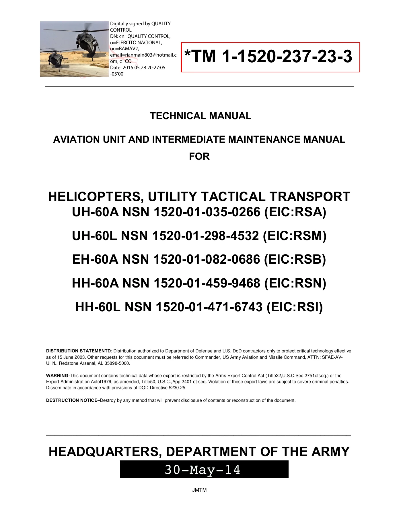
Sikorsky UH-60A UH-60L EH-60A HH-60A HH-60L Aviation Unit and Intermediate Maintenance Manual TM 1-1520-237-23-3 Volume 3 (2014) - PDF Download — PDF page 1 preview
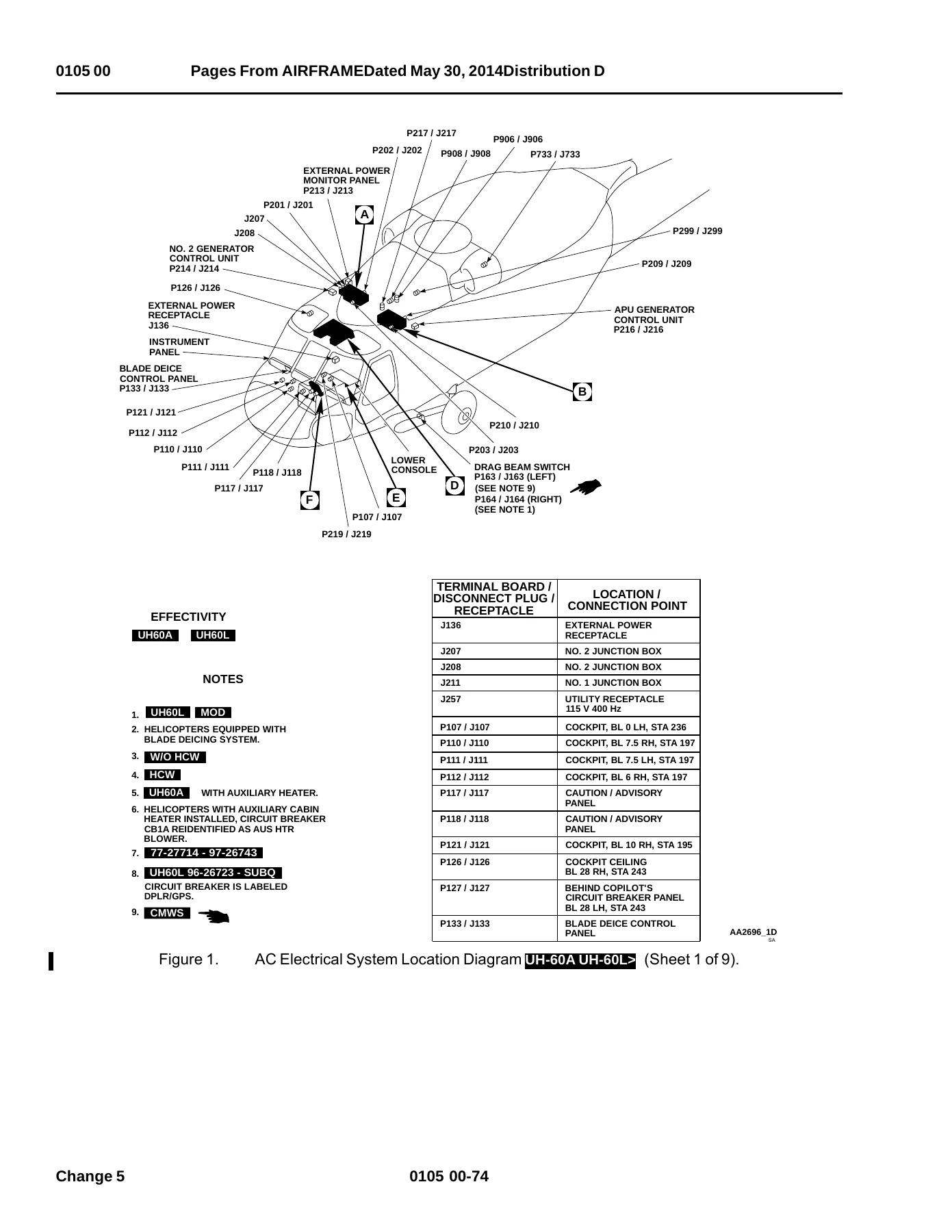
Sikorsky UH-60A UH-60L EH-60A HH-60A HH-60L Aviation Unit and Intermediate Maintenance Manual TM 1-1520-237-23-3 Volume 3 (2014) - PDF Download — PDF page 80 preview
Sikorsky UH-60A UH-60L EH-60A HH-60A HH-60L Aviation Unit and Intermediate Maintenance Manual TM 1-1520-237-23-3 Volume 3 (2014) - PDF Download — PDF page 187 preview

Taken as a whole, the volume hands the technician a complete operational and troubleshooting framework for the aircraft’s electrical distribution, external and cockpit lighting, fuel delivery and quantity measurement, and mechanical flight control systems. Every work package is laid out as an Operational Checkout Test Procedure followed by numbered corrective-action branches, so a fault is isolated by following the same sequence a flight-line technician would use on the aircraft. Most work packages close with a dedicated troubleshooting procedure keyed to specific symptoms — for example the “NO. 1 PUMP LIGHT DID NOT GO ON AND #1 FUEL PRESS CAPSULE OR LEGENDS DID NOT GO OFF” branch in the submerged fuel boost pump system — and each branch ends in a terminal corrective action such as replacing a relay, contactor, circuit breaker, probe, actuator or wiring run.

What This Manual Lets You Do

This is a full troubleshooting document, not a simple description. It gives you the actual component identifiers, wire terminations, test points, voltages and resistance values needed to trace a fault through the Sikorsky UH-60A/UH-60L/EH-60A/HH-60A/HH-60L electrical and flight control systems.

Typical jobs the manual supports include:

  • Troubleshooting the AC electrical system from the APU generator, No. 1 and No. 2 generator systems, and AC external power through to the 26 VAC power system and the 115 VAC 3Ø 400 Hz utility receptacle.
  • Isolating DC electrical faults in the battery circuit, No. 1 and No. 2 converters, utility DC, mission interface power on the EH-60A, and the UH-60L battery low sensing and shutdown functions.
  • Diagnosing cockpit, cabin, console, instrument panel, formation, position, anti-collision, searchlight, landing light and cargo hook lighting faults.
  • Fault isolation on the fuel low level warning system, submerged fuel boost pump system, fuel prime boost system, pressure refuel/defuel system, and the fuel quantity system using Test Set TF-579 or Test Set PSD60-1AF.
  • Using the AVIM-level procedures for the fuel boost pump control panel, ECM antenna actuator assembly, and the left and right hand relay panels, including the T1 current sensor, the K20 DC essential bus fail relay, the K21 windshield anti-ice lockout relay, the K26 No. 2 engine start relay, the K32 hydraulic accumulator relay, the K41 searchlight relay, and the K45 No. 1 engine start relay.
  • Checking the cyclic stick assembly grip and slew-up switch, and the collective stick assembly, against the resistance tables and continuity checks the manual provides.
  • Performing the binding, in-flight attitude oscillation, and flight control noise checkout procedures on the mechanical flight controls, including rod inspection for loose swaged inserts and riveted-type pushrod rod ends.
  • Bench-testing the Roll SAS assembly, Yaw Boost assembly, Pitch Trim actuator and Pilot-assist module using the specified nulling fixtures and test setups.

Why It Matters

On a UH-60-series helicopter, a misdiagnosed electrical or flight control fault is not just an inconvenience — it can cascade into a grounded airframe or a safety issue. The manual’s step-by-step corrective actions are the difference between swapping parts and correctly isolating the failed relay, contactor, circuit breaker, wiring run, limit switch or servo. Values such as the specified 21 to 27 volt regulator bus voltage, the 112.5 to 117.5 VAC generator output window, the 380 to 420 Hz frequency range, and the specific resistance bands for the fuel low level thermistors are all included so a technician can confirm a good component against a known reference.

Complete PDF Bookmark Tree

Complete Bookmarks

The complete bookmarks in the “Sikorsky UH-60A UH-60L EH-60A HH-60A HH-60L Aviation Unit and Intermediate Maintenance Manual TM 1-1520-237-23-3 Volume 3 (2014) – PDF Download” are as follows:

Binder1p. 1
TM 1-1520-237-23-3 TROUBLESHOOTING PROCEDURES 1p. 1
TM 1-1520-237-23-3 TROUBLESHOOTING PROCEDURES 2p. 2
TM 1-1520-237-23-3 TROUBLESHOOTING PROCEDURES 3p. 3
TM 1-1520-237-23-3 TROUBLESHOOTING PROCEDURES 4p. 4
TM 1-1520-237-23-3 TROUBLESHOOTING PROCEDURES 5p. 5
TM 1-1520-237-23-3 TROUBLESHOOTING PROCEDURES 6p. 6
Binder2p. 7
wp0105p. 7
tocp. 7
AC Electrical Systemp. 7
Special Instructionsp. 7
APU Generator System Operational/Troubleshooting Procedurep. 8
NO. 1 Generator System Operational/Troubleshooting Procedurep. 11
NO. 2 Generator System Operational/Troubleshooting Procedurep. 14
AC External Power System Operational/Troubleshooting Procedurep. 17
Mission Interface Panel Ground Power Operational/Troubleshootingp. 19
Mission Interface Panel Single Generator Power Operational/Troubp. 22
Mission Interface Panel Dual Generators Power Operational/Troublp. 25
Mission Interface Panel Auxiliary Power Operational/Troubleshootp. 28
26 VAC Power System Operational/Troubleshooting Procedurep. 32
UTIL RCPT 115 VAC 3ø 400 HZ Operational/Troubleshooting Procedurp. 34
60 HZ AC Converter Receptacle Operational/Troubleshooting Procedp. 35
Generator And GCU Operational/Troubleshooting Procedurep. 36
AC ESS BUS OFF CAPSULE DOES NOT GO ON WITHOUT POWER ON AC ESNTLp. 43
WITH GENERATORS APU SWITCH ON, APU GEN ON CAPSULE DOES NOT GO ONp. 43
APU GEN ON CAPSULE IS OFF WITH APU GENERATOR SUPPLYING BUSES (#1p. 47
APU GENERATOR OR AC EXTERNAL POWER DOES NOT SUPPLY NO. 1 AC PRIp. 48
AC ESS BUS OFF CAPSULE DOES NOT GO OFF WHEN NO. 1 AND NO. 2 AC Pp. 49
#1 GEN BRG AND/OR #2 GEN BRG CAPSULE GOES ONp. 51
#1 GEN CAPSULE DOES NOT GO ON WITH NO. 1 GENERATOR OFFp. 52
#1 GEN CAPSULE IS ON WITH GENERATORS NO. 1 SWITCH ONp. 54
#1 CONV CAPSULE STAYS ON WHEN EITHER GENERATOR IS SUPPLYING POWEp. 56
#2 CONV CAPSULE STAYS ON WHEN EITHER GENERATOR IS SUPPLYING POWEp. 57
NO. 1 AND/OR NO. 2 GENERATOR DISABLED BY UNDERFREQUENCY CONDITIOp. 58
#2 GEN CAPSULE IS OFF WITH NO. 2 GENERATOR OFFp. 60
#2 GEN CAPSULE IS ON WITH GENERATORS NO. 2 SWITCH ONp. 61
EXT PWR CONNECTED CAPSULE IS OFF WITH A SOURCE OF EXTERNAL POWERp. 64
EXTERNAL POWER DOES NOT SUPPLY AC BUSES (#1 CONV AND #2 CONV CAPp. 65
NO POWER AT MISSION INTERFACE PANEL WITH EXTERNAL POWER APPLIEDp. 67
115 VAC AT MISSION INTERFACE PANEL WITH EXTERNAL POWER CONNECTEDp. 69
NO POWER AT MISSION INTERFACE PANEL WITH NO. 1 OR NO. 2 GENERATOp. 70
NO POWER AT MISSION INTERFACE PANEL WITH NO. 1 AND NO. 2 GENERATp. 72
NO EMERGENCY AUXILIARY POWER AT MISSION INTERFACE PANELp. 74
BLADE DE-ICE SYSTEM DOES NOT DISABLE AUXILIARY POWER WITH BLADEp. 77
115 VAC AT MISSION INTERFACE PANEL WITH NO. 1 AND NO. 2 GENERATOp. 78
NO 26 VAC POWER ON AC ESNTL BUSp. 78
Schematicsp. 98
tablesp. 7
Table 1.Temperature Requirements.p. 8
wp0106p. 158
tocp. 158
DC Electrical Systemp. 158
Special Instructionsp. 158
Battery Operational/Troubleshooting Procedurep. 159
No. 1 Converter Operational/Troubleshooting Procedurep. 160
No. 2 Converter Operational/Troubleshooting Procedurep. 161
Utility DC UH60A UH60L> . Operational/Troubleshooting Procedurp. 163
Mission Interface Power EH60A> . Operational/Troubleshooting Pp. 164
Battery Low Sensing UH60L 96-26723 – SUBQ> . Operational/Troublep. 166
Shutdown Operational/Troubleshooting Procedurep. 167
NO CAUTION/ADVISORY CAPSULES GO ON WHEN BATT SWITCH IS PLACED TOp. 168
NO CAUTION/ADVISORY CAPSULES GO ON WHEN BATT SWITCH IS PLACED TOp. 172
BATT LOW CHARGE CAPSULE IS ON WHEN BATT SWITCH IS SET TO ON 77-2p. 175
BATT LOW CHARGE CAPSULE IS ON WHEN BATT SWITCH IS SET TO ON UH60p. 176
DC ESS BUS OFF CAPSULE IS ON WHEN BATT SWITCH IS SET TO ONp. 176
#1 AND #2 CONV CAPSULES ARE NOT ONp. 177
#1 CONV CAPSULE IS NOT ONp. 177
#2 CONV CAPSULE IS NOT ONp. 178
#1 CONV CAPSULE IS ONp. 179
DC ESS BUS OFF CAPSULE IS OFF WITH ESNTL DC SENSE CIRCUIT BREAKEp. 180
#2 CONV CAPSULE IS ONp. 181
NO 28 VDC INDICATION BETWEEN J258-A AND J258-B EH60A> .p. 182
NO VOLTAGE ON J512 EH60A>. .p. 184
BATT LOW CHARGE CAPSULE IS On When Battery Voltage Is 24 VDC UH6p. 184
BATT LOW CHARGE CAPSULE IS OFF WHEN BATTERY VOLTAGE IS 22 VDC UHp. 185
Schematicsp. 201
wp0107p. 232
tocp. 232
Mission Electrical Interface EH60A> .p. 232
Mission Electrical Interface Operational/Troubleshooting Procedup. 232
Schematicsp. 239
tablesp. 232
Table 1.Temperature Requirements.p. 232
wp0108p. 240
tocp. 240
System Circuit Breakersp. 240
System Circuit Breakers Operational/Troubleshooting Procedurep. 240
wp0109p. 241
tocp. 241
Instrument Panel Lightsp. 241
Instrument Panel Lights Operational/Troubleshooting Procedurep. 241
NO NONFLIGHT INSTRUMENT PANEL LIGHTS GO ONp. 244
ICING RATE METER LIGHT DOES NOT GO ONp. 245
PILOT'S AND/OR COPILOT'S COLLECTIVE STICK GRIP LIGHTING DOES NOTp. 246
NO PILOT'S FLIGHT INSTRUMENT PANEL LIGHTS GO ONp. 247
LIGHTS ON PILOT'S STABILATOR POSITION PLACARD AND PILOT'S HSI/VSp. 248
NO COPILOT'S FLIGHT INSTRUMENT PANEL LIGHTS GO ONp. 249
LIGHTS ON COPILOT'S STABILATOR POSITION PLACARD AND COPILOT'S HSp. 250
AUXILIARY FUEL MANAGEMENT CONTROL PANEL LIGHTS DO NOT GO ONp. 251
Schematicsp. 264
wp0110p. 270
tocp. 270
Upper and Lower Console Lightsp. 270
Upper And Lower Console Lights Operational/Troubleshooting Procep. 270
LOWER CONSOLE CONTROL PANEL LIGHTS, TROOP COMMANDER'S, LEFT GUNNp. 273
RESCUE HOIST CONTROL PANEL, RANGE EXTENSION KIT CONTROL PANEL, Sp. 274
COMMUNICATION SYSTEM CONTROL PANELS LIGHTING DOES NOT GO FROM DIp. 274
RESCUE HOIST, RANGE EXTENSION, STABILATOR, MISC SW, RADIO RETRANp. 274
IF MISC SW CONTROL PANEL, RADIO RETRANSMISSION CONTROL PANEL, COp. 275
NO. 1 AND NO. 2 VHF/FM RADIO SET CONTROL (AN/ARC-201) LIGHTING Sp. 276
UPPER CONSOLE LIGHTING DOES NOT GO ONp. 287
Schematicsp. 298
tablesp. 270
Table 1.Individual Lower Console Control Panel Lighting Check W/p. 276
Table 2.Individual Lower Console Control Panel Lighting Check MWp. 280
Table 3.Individual Upper Console Panel Lighting Checks.p. 288
wp0111p. 323
tocp. 323
Cabin Dome Lightsp. 323
Cabin Dome Lights Operational/Troubleshooting Procedurep. 323
NO WHITE CABIN DOME LIGHTS GO ONp. 324
Schematicsp. 328
wp0112p. 329
tocp. 329
Cockpit Flood and Secondary Lightsp. 329
Cockpit Flood And Secondary Lights Operational/Troubleshooting Pp. 329
Glare Shield Lights Do Not Go On With GLARESHIELD LIGHTS Controlp. 331
Neither Cockpit White Flood Light Goes Onp. 331
Light On Standby Magnetic Compass Does Not Go Onp. 332
Schematicsp. 335
wp0113p. 336
tocp. 336
Utility And Maintenance Lightsp. 336
Special Instructionsp. 336
Utility And Maintenance Lights Operational/Troubleshooting Procep. 336
UTILITY LIGHT DOES NOT GO ONp. 338
Maintenance Light Does Not Go On When Connected To One Maintenanp. 339
Schematicsp. 343
wp0114p. 344
tocp. 344
Instrument Panel And Consoles Indicator Lights Dimmingp. 344
Instrument Panel And Consoles Indicator Lights Dimming Operationp. 344
Instrument Panel And Consoles Indicator Lights Do Not Go On Brigp. 350
Pilot's and Copilot's Radar Altimeter Digital Displays Do Not Gop. 350
Lighted Switches on Selected Panels, or Displays And Annunciatorp. 351
Indicator Lights Do Not Dimp. 352
Pilot's or Copilot's Radar Altimeter Digital Displays Do Not Dimp. 353
T-Handles Remain Brightp. 354
Schematicsp. 362
wp0115p. 372
tocp. 372
Formation Lightsp. 372
Formation Lights Operational/Troubleshooting Procedurep. 372
NO FORMATION LIGHTS GO ONp. 375
One Formation Light Does Not Go Onp. 376
No IR (Bright) Formation Lights Go On With FORMATION LT Controlp. 377
One IR (Bright) Formation Light Does Not Go Onp. 378
Schematicsp. 382
wp0116p. 386
tocp. 386
Controllable Searchlightp. 386
Controllable Searchlight Operational/Troubleshooting Procedurep. 386
Searchlight Does Not Extend with Pilot's Searchlight Control Pusp. 390
Searchlight Does Not Turn Right with Pilot's Searchlight Controlp. 391
Searchlight Does Not Turn Left with Pilot's Searchlight Controlp. 392
Searchlight Does Not Retract with Pilot's Searchlight Control Pup. 392
Searchlight Does Not Extend with Copilot's Searchlight Control Pp. 393
Searchlight Does Not Turn Right with Copilot's Searchlight Contrp. 394
Searchlight Does Not Turn Left with Copilot's Searchlight Controp. 394
Searchlight Does Not Retract with Copilot's Searchlight Controlp. 395
Searchlight Does Not Light with Pilot's SRCH LT Switch ONp. 395
Searchlight Does Not Decrease in Brilliance and Go Off with Pilop. 397
Searchlight Does Not Increase in Brilliance with Pilot's SRCH LTp. 398
Searchlight Does Not Light with Copilot's SRCH LT Switch ONp. 398
Searchlight Does Not Decrease in Brilliance and Go Off with Copip. 399
Searchlight Does Not Increase in Brilliance and Go Off with Copip. 399
Schematicsp. 403
wp0117p. 406
tocp. 406
Position Lightsp. 406
Position Lights Operational/Troubleshooting Procedurep. 406
Incandescent Position Lights Do Not Go Onp. 409
One Incandescent Position Light Does Not Go Onp. 410
Incandescent Position Lights Do Not Light at a Reduced Intensityp. 411
Incandescent Position Lights Do Not Flashp. 411
IR Lights Do Not Go Onp. 412
One IR Position Light Does Not Go Onp. 413
Schematicsp. 417
wp0118p. 421
tocp. 421
Retractable Landing Lightp. 421
Retractable Landing Light Operational/Troubleshooting Procedurep. 421
Landing Light Does Not Move with Pilot's LDG LT Switch Moved top. 424
Landing Light Does Not Move with Pilot's LDG LT Switch Moved top. 425
Landing Light Does Not Go On when Pilot's LDG LT Switch is Pressp. 425
Landing Light Does Not Go Off when Pilot's LDG LT Switch is Presp. 427
Landing Light Does Not Go On when Copilot's LDG LT Switch is Prep. 427
Landing Light Does Not Go Off when Copilot's LDG LT Switch is Prp. 427
Schematicsp. 430
wp0119p. 432
tocp. 432
Anti-collision Lightsp. 432
Anti-Collision Lights Operational/Troubleshooting Procedurep. 432
Neither Anti-Collision Light Flashes Whitep. 434
One Anti-Collision Light Does Not Flash White with Anti Collisiop. 435
Neither Anti-Collision Light Flashes Redp. 437
One Anti-Collision Light Does Not Flash Red with Switch Set to Bp. 437
Upper Anti-Collision Light Does Not Flash with Anti Collision Lip. 438
Schematicsp. 441
wp0120p. 442
tocp. 442
Cargo Hook Lights UH-60A UH-60L HH-60A HH-60L> .p. 442
Cargo Hook Lights Operational/Troubleshooting Procedure W/O MWOp. 442
Cargo Hook Lights Operational/Troubleshooting Procedure MWO 50-5p. 443
No Cargo Hook Lights Go On W/O MWO 50-56> .p. 444
No Cargo Hook Lights Go On with HOOK LIGHT Control Panel Knob Fup. 445
Schematicsp. 448
wp0121p. 450
tocp. 450
ECM Antenna Actuator Assembly EH60A>. .p. 450
Special Instructionsp. 450
ECM Antenna Actuator Assembly Operational/Troubleshooting Procedp. 450
Antenna Retracted Capsule Does Not Go On when Power is Applied tp. 454
ECM Antenna Actuator Assembly Clevis Does Not Pivot from Retractp. 455
ECM Antenna Actuator Assembly Clevis Does Not Pivot from Extendep. 456
Antenna Extended Capsule Does Not Go On when ECM Antenna Clevisp. 456
Schematicsp. 465
wp0122p. 467
tocp. 467
Fuel Boost Pump Control Panel (AVIM)p. 467
Fuel Boost Pump Control Panel (AVIM) Operational/Troubleshootingp. 467
Schematicsp. 473
wp0123p. 474
tocp. 474
ECM Antenna Actuator Assembly (AVIM) EH60A>. .p. 474
ECM Antenna Actuator Assembly (AVIM) Operational/Troubleshootingp. 474
Meter Does Not Indicate Continuity with ECM Actuator Assembly inp. 477
END OF WORK PACKAGEp. 479
wp0124p. 480
tocp. 480
Right Hand Relay Panel (AVIM)p. 480
Special Instructionsp. 480
T1 Current Sensor Operational/Troubleshooting Procedurep. 480
K20 DC Essential Bus Fail Relay Operational/Troubleshooting Procp. 481
K21 Windshield Anti-Ice Lockout Relay Operational/Troubleshootinp. 482
K26 No. 2 Engine Start Relay Operational/Troubleshooting Procedp. 483
K32 Hydraulic Accumulator Relay Operational/Troubleshooting Procp. 485
Shutdown Operational/Troubleshooting Procedurep. 486
Test Lamp Stays Onp. 486
Test Lamp Stays Offp. 487
K21 Windshield Anti-Ice Lockout Relay Test Failsp. 487
K26 No. 2 Engine Start Relay Test Failsp. 488
K32 Hydraulic Accumulator Relay Test Failsp. 489
Test Setupp. 493
Schematicsp. 493
wp0125p. 498
tocp. 498
Left Hand Relay Panel (AVIM)p. 498
Special Instructionsp. 498
T1 Current Sensor Operational/Troubleshooting Procedurep. 498
K41 Searchlight Relay 70550-02105-048, And -050 Operational/Troup. 499
K41 Searchlight Relay 70550-02105-051, -054, And -057 Operationap. 501
K45 No. 1 Engine Start Relay Operational/Troubleshooting Procedup. 501
Shutdown Operational/Troubleshooting Procedurep. 503
Test Lamp Stays Onp. 503
Test Lamp Stays Offp. 504
K41 Searchlight Relay Test Failsp. 505
K41 Searchlight Relay Test Failsp. 508
K45 No. 1 Engine Start Relay Test Failsp. 512
Test Setupp. 515
Schematicsp. 516
wp0126p. 520
tocp. 520
AC Electrical System HH-60A HH-60L> .p. 520
Special Instructionsp. 520
APU Generator System Operational/Troubleshooting Procedurep. 521
No. 1 Generator System Operational/Troubleshooting Procedurep. 523
No. 2 Generator System Operational/Troubleshooting Procedurep. 526
AC External Power System Operational/Troubleshooting Procedurep. 528
26 VAC Power System Operational/Troubleshooting Procedurep. 530
UTIL RCPT 115 VAC 3ø 400 HZ Receptacle Operational/Troubleshootip. 531
60 Hz AC Converter Receptacle Operational/Troubleshooting Procedp. 532
Generator And GCU Operational/Troubleshooting Procedurep. 533
AC ESS BUS OFF Legend Does Not Go On Without Power On AC ESNTL Bp. 539
With GENERATORS APU Switch ON, APU GEN ON Legend Does Not Go Onp. 540
APU GEN ON Legend Is Off With APU Generator Supplying Buses (#1p. 543
APU Generator Or AC External Power Does Not Supply No. 1 AC PRIp. 544
AC ESS BUS OFF Legend Does Not Go Off When No. 1 And No. 2 AC Prp. 544
#1 GEN BRG And/Or #2 GEN BRG Legend Goes Onp. 546
#1 GEN Legend Does Not Go On With No. 1 Generator Offp. 547
#1 GEN Legend Is On With GENERATORS NO. 1 Switch ONp. 548
#1 CONV Legend Stays On When Either Generator Is Supplying Powerp. 550
#2 CONV Legend Stays On When Either Generator Is Supplying Powerp. 551
No. 1 And/Or No. 2 Generator Disabled By Underfrequency Conditiop. 552
#2 GEN Legend Is Off With No. 2 Generator Offp. 553
#2 GEN Legend Is On ith GENERATORS NO. 2 Switch ONp. 554
EXT PWR CONNECTED Legend Is Off With A Source Of External Powerp. 556
External Power Does Not Supply AC Buses (#1 CONV And #2 CONV Legp. 557
No 26 VAC Power On AC ESNTL Busp. 560
Schematicsp. 569
tablesp. 520
Table 1.Temperature Requirements.p. 521
wp0127p. 601
tocp. 601
DC Electrical System HH-60A HH-60L> .p. 601
Special Instructionsp. 601
Battery Operational/Troubleshooting Procedurep. 601
External Electrical Power Operational/Troubleshooting Procedurep. 602
No. 1 Converter Operational/Troubleshooting Procedurep. 603
No. 2 Converter Operational/Troubleshooting Procedurep. 605
Utility DC Operational/Troubleshooting Procedurep. 606
Battery Low Sensing Operational/Troubleshooting Procedurep. 607
Shutdown Operational/Troubleshooting Procedurep. 609
No MFD (Copilot's And Pilot's) Legends Go On When BATT Switch Isp. 609
BATT Low Charge Legend Is On When BATT Switch Is Set To ONp. 612
DC ESS BUS OFF Legend Is On When BATT Switch Is Set To ONp. 612
#1 And #2 CONV Legends Are Not Onp. 613
#1 CONV Legend Is Not Onp. 613
#2 CONV Legend Is Not Onp. 614
DC ESS BUS OFF Legend Does Not Go On When ESNTL DC SENSE Circuitp. 614
#1 CONV Legend Is Onp. 615
DC ESS BUS OFF Legend Is Off With ESNTL Supply Bus Circuit Breakp. 616
#2 CONV Legend Is Onp. 617
BATT LOW CHARGE Legend On Pilot's MFD Does Not Go On When Batterp. 618
BATT LOW CHARGE Legend On Copilot's MFD Does Not Go On When Battp. 619
BATT LOW CHARGE Legend On Pilot's And Copilot's MFD Does Not Gop. 619
Schematicsp. 627
wp0128p. 649
tocp. 649
Upper And Lower Console Lights HH-60A HH-60L> .p. 649
Upper And Lower Console Lights Operational/Troubleshooting Procep. 649
Lower Console 0-115 vac Lighting Failsp. 652
Upper Console Lighting Does Not Go Onp. 654
Lower Console 0-5 vac Lighting Failsp. 655
Schematicsp. 663
tablesp. 649
Table 1.Lower Console 0-115 Vac Auxiliary Lighting Checks.p. 652
Table 2.Upper Console Panel Lighting Checks.p. 654
Table 3.Lower Console 0-5 Vac Auxiliary Lighting Checks.p. 656
wp0129p. 669
tocp. 669
Instrument Panel Lights HH-60A HH-60L> .p. 669
Instrument Panel Lights Operational/Troubleshooting Procedurep. 669
Stabilator Placard, Stabilator Indicator Bezel, And Pilot's Andp. 672
Stabilator Placard Lighting Fails To Come Onp. 672
Stabilator Indicator Lighted Bezel Fails To Come Onp. 673
Pilot's Collective Stick Grip Information Panel Lighting Fails Tp. 674
Copilot's Collective Stick Grip Information Panel Lighting Failsp. 674
NONE OF THE BEZELS OR LIGHTS GO ONp. 674
Pilot's Mode Sel Panel Lighting Failsp. 675
None Of The Bezels Or Lights Go Onp. 676
Copilot's MODE SEL Panel Lighting Failsp. 677
Schematicsp. 683
tablesp. 669
Table 1.Individual Bezel or Light Does Not Go On.p. 675
Table 2.Individual Bezel or Light Does Not Go On.p. 676
wp0130p. 686
tocp. 686
Instrument Panel And Consoles Indicator Lights Dimming HH-60A Hp. 686
Instrument Panel And Consoles Indicator Lights Dimming Operationp. 686
Instrument Panel And Console Indicator Lights Do Not Go On Brighp. 690
Indicator Lights Do Not Dimp. 692
Lighted Switches Function Inoperativep. 693
Pilot's and Copilot's Radar Altimeter Digital Display and Warninp. 693
Schematicsp. 705
tablesp. 686
Table 1.Indicator Light Checks, Bright Mode.p. 690
Table 2.Press-To-Test Indicator Checks.p. 691
wp0131p. 710
tocp. 710
Fuel Low Level Warning Systemp. 710
Fuel Low Level Warning System Operational/Troubleshooting Procedp. 710
No Fuel Low Indication From One Tank With Fuel Level Below 170 Tp. 712
Fuel Low Indication On One Tank With Fuel Quantity Greater Thanp. 714
No Fuel Low Indication From Both Tanks With Fuel Below 170 To 18p. 715
Schematicsp. 720
wp0132p. 722
tocp. 722
Submerged Fuel Boost Pump Systemp. 722
Submerged Fuel Boost Pump System Operational/Troubleshooting Prop. 722
NO. 1 PUMP Light Did Not Go On And #1 FUEL PRESS Capsule Or Legep. 725
#1 FUEL PRESS Capsule Or Legends Go Off, But NO. 1 PUMP Light Dop. 727
NO. 1 PUMP Light Goes On, But #1 FUEL PRESS Capsule Or Legends Dp. 728
NO. 1 PUMP Light Does Not Go Off When NO. 1 PUMP Switch Is Placep. 728
NO. 2 PUMP Light Did Not Go On And #2 FUEL PRESS Capsule Or Legep. 729
#2 FUEL PRESS Capsule Or Legends Go Off, But NO. 2 PUMP Light Dop. 730
NO. 2 PUMP Light Goes On, But #2 FUEL PRESS Capsule Or Legends Dp. 731
NO. 2 PUMP Pressure Light Does Not Go Off When NO. 2 PUMP Switchp. 732
NO. 2 PUMP Light Did Not Go On And #1 FUEL PRESS Capsule Or Legep. 733
#1 FUEL PRESS Capsule Or Legends Go Off, But NO. 2 PUMP Light Dop. 734
NO. 2 PUMP Light Goes On, But #1 FUEL PRESS Capsule Or Legends Dp. 735
NO. 1 PUMP Light Did Not Go On And #2 FUEL PRESS Capsule Or Legep. 736
#2 FUEL PRESS Capsule Or Legends Go Off, But NO. 1 PUMP Light Dop. 737
NO. 1 PUMP Light Goes On, But #2 FUEL PRESS Capsule Or Legends Dp. 738
Schematicsp. 746
wp0133p. 753
tocp. 753
Fuel Prime Boost Systemp. 753
Fuel Prime Boost System Operational/Troubleshooting Procedurep. 753
PRIME BOOST PUMP ON Capsule Or Legends Not On, And Boost Pump Nop. 757
PRIME BOOST PUMP ON Capsule Or Legends On, Boost Pump Not Operatp. 758
PRIME BOOST PUMP ON Capsule Or Legends On And Pump Operating, Bup. 758
NO. 1 Or NO. 2 ENG FUEL SYS Selector Lever Does Not Move Or Is Dp. 759
No Fuel Coming Out Of No. 1 Engine Fuel Drainp. 759
No Fuel Coming Out Of No. 2 Engine Fuel Drainp. 761
Schematicsp. 765
wp0134p. 770
tocp. 770
Pressure Refuel/Defuel Systemp. 770
Special Instructionsp. 770
Pressure Fueling Operational/Troubleshooting Procedurep. 770
Pressure Defueling Operational/Troubleshooting Procedurep. 771
Schematicsp. 776
wp0135p. 778
tocp. 778
Fuel Quantity System Using Test Set TF-579p. 778
Special Instructionsp. 778
Dry Method Operational/Troubleshooting Procedurep. 778
Wet Method Operational/Troubleshooting Procedurep. 784
Probe Capacitance Is Not 69.8 To 71.4 pfp. 789
Multimeter Does Not Indicate Specified Voltage For No. 1 Tankp. 790
FUEL QTY 1 Vertical Indicator Not As Specifiedp. 791
Multimeter Does Not Indicate Specified Voltage For No. 2 Tankp. 792
FUEL QTY 2 Vertical Indicator Not As Specifiedp. 793
No FUEL IND TEST Functionp. 794
Digital Display Does Not Indicate Greater Than 1 Megohmp. 794
Digital Display Does Not Indicate 0 (Zero) Megohmp. 795
Schematicsp. 802
Test Setupp. 804
Test Setupp. 805
tablesp. 778
Table 1.Worksheet 1-A. Dry Method (Preferred).p. 796
Table 2.Worksheet 1-B. Wet Method (Alternate).p. 797
wp0136p. 806
tocp. 806
Fuel Quantity System Using Test Set PSD60-1AFp. 806
Special Instructionsp. 806
Dry Method Operational/Troubleshooting Procedurep. 806
Wet Method Operational/Troubleshooting Procedurep. 812
Probe Capacitance Is Not 69.1 To 72.1 pfp. 816
Multimeter Does Not Indicate Specified Voltage For No. 1 Tankp. 817
FUEL QTY 1 Vertical Indicator Not As Specifiedp. 818
Multimeter Does Not Indicate Specified Voltage For No. 2 Tankp. 819
FUEL QTY 2 Vertical Indicator Not As Specifiedp. 820
No FUEL IND TEST Functionp. 821
Digital Display Does Not Indicate Greater Than 1 Megohmp. 822
Digital Display Does Not Indicate 0 (Zero) Megohmp. 822
Schematicsp. 828
Test Setupp. 830
tablesp. 806
Table 1.Worksheet 1-A. Dry Method (Preferred).p. 823
Table 2.Worksheet 1-B. Wet Method (Alternate).p. 824
wp0137p. 831
tocp. 831
Fuel Quantity System Harness Adapter (AVIM)p. 831
Fuel Quantity System Harness Adapter (AVIM) Operational/Troublesp. 831
NO CONTINUITY BETWEEN P5 AND J1-Bp. 836
NO CONTINUITY BETWEEN P4 AND J1-Mp. 837
NO CONTINUITY BETWEEN P3 AND P1-Bp. 837
NO CONTINUITY BETWEEN P2 AND P1-Mp. 838
NO CONTINUITY BETWEEN P5 AND J1-Dp. 839
NO CONTINUITY BETWEEN P4 AND J1-Np. 839
NO CONTINUITY BETWEEN P3 AND P1-Dp. 840
NO CONTINUITY BETWEEN P2 AND P1-Np. 840
Schematicsp. 842
wp0138p. 844
tocp. 844
Cyclic Stick Assemblyp. 844
Special Instructionsp. 844
Grip Assembly Electrical Operational/Troubleshooting Procedurep. 844
Slew-Up Switch Electrical Operational/Troubleshooting Procedurep. 846
Grip Assembly Mechanical Inspection Operational/Troubleshootingp. 848
Slew-Up Switch Mechanical Inspection Operational/Troubleshootingp. 849
Schematicsp. 854
tablesp. 844
Table 1.Grip Assembly Resistance Check .p. 844
Table 2.Slew-Up Resistance Check ( EH-60A 89-24667-SUBQ UH-60A 8p. 847
Table 3.Slew-Up Resistance Check ( EH-60A 84-24017 – 88-26046 UHp. 848
wp0139p. 858
tocp. 858
Collective Stick Assemblyp. 858
Special Instructionsp. 858
Electrical Operational/Troubleshooting Procedurep. 859
Mechanical Inspection, Pilot Operational/Troubleshooting Procedup. 876
Mechanical Inspection, Copilot Operational/Troubleshooting Procep. 877
Lighted Panel Is Not Lit Correctlyp. 877
Friction Grip Does Not Work And/Or Stick Does Not Move Smoothlyp. 878
Schematicsp. 883
tablesp. 858
Table 1.Continuity Check ( UH-60A 85-24415 – SUBQ MOD UH-60L EH-p. 859
Table 2.Continuity Check ( UH-60A 77-22714 – 85-24414 W/O MOD>.p. 866
wp0140p. 886
tocp. 886
Flight Controls (Mechanical)p. 886
Special Instructionsp. 887
Binding Operational/Troubleshooting Procedurep. 887
In-Flight Attitude Oscillations Operational/Troubleshooting Procp. 890
Flight Control Noise Checkout Operational/Troubleshooting Procedp. 893
CYCLIC STICK IS DIFFICULT TO MOVE FORWARD AND AFTp. 896
CYCLIC STICK IS DIFFICULT TO MOVE LEFT AND RIGHTp. 897
TAIL ROTOR QUADRANT CAPSULE OR HH-60A HH-60L >. TAIL RTR QUADRANp. 898
EXCESSIVE FREE PLAY IN TAIL ROTOR PEDALSp. 899
PEDALS ARE DIFFICULT TO MOVEp. 899
COLLECTIVE STICK REQUIRES GREATER FORCE TO MOVE IN ONE DIRECTIONp. 901
COLLECTIVE STICK IS DIFFICULT TO MOVE UP AND DOWNp. 901
TAIL ROTOR QUADRANT CAPSULE OR HH-60A HH-60L >. TAIL RTR QUADRANp. 902
NOISE IS HEARD WHILE MOVING PILOT CYCLIC STICK FROM LEFT TO RIGHp. 904
NOISE IS HEARD WHILE MOVING PILOT CYCLIC STICK FROM FORWARD TO Ap. 907
NOISE IS HEARD WHILE MOVING COLLECTIVE STICK UP AND DOWNp. 911
NOISE IS HEARD WHILE PUSHING ON LEFT AND RIGHT PEDALp. 915
Schematicsp. 925
tablesp. 886
Table 1.Temperature Requirements.p. 887
wp0141p. 927
tocp. 927
Roll SAS Assembly (AVIM)p. 927
Roll SAS Assembly (AVIM) Operational/Troubleshooting Procedurep. 927
Test Setupp. 932
wp0142p. 935
tocp. 935
Yaw Boost Assembly (AVIM)p. 935
Yaw Boost Assembly (AVIM) Operational/Troubleshooting Procedurep. 935
Test Setupp. 940
wp0143p. 943
tocp. 943
Pitch Trim Actuator (AVIM)p. 943
Pitch Trim Actuator (AVIM) Operational/Troubleshooting Procedurep. 943
Test Setupp. 948
wp0144p. 951
tocp. 951
Pilot-assist Module (AVIM)p. 951
Pilot-assist Module (AVIM) Operational/Troubleshooting Procedurep. 951
Test Setupp. 955
Binder3p. 957
TM 1-1520-237-23-3 TROUBLESHOOTING PROCEDURES 946p. 957
TM 1-1520-237-23-3 TROUBLESHOOTING PROCEDURES 947p. 958
TM 1-1520-237-23-3 TROUBLESHOOTING PROCEDURES 948p. 959
TM 1-1520-237-23-3 TROUBLESHOOTING PROCEDURES 949p. 960
TM 1-1520-237-23-3 TROUBLESHOOTING PROCEDURES 950p. 961
TM 1-1520-237-23-3 TROUBLESHOOTING PROCEDURES 951p. 962
TM 1-1520-237-23-3 TROUBLESHOOTING PROCEDURES 952p. 963
TM 1-1520-237-23-3 TROUBLESHOOTING PROCEDURES 953p. 964
TM 1-1520-237-23-3 TROUBLESHOOTING PROCEDURES 954p. 965
TM 1-1520-237-23-3 TROUBLESHOOTING PROCEDURES 955p. 966
TM 1-1520-237-23-3 TROUBLESHOOTING PROCEDURES 956p. 967

The volume also includes the schematic and location diagrams that turn a wire number into a physical connector. AC electrical system location diagrams, AC electrical system schematic diagrams, AC power distribution diagrams, DC electrical system location and schematic diagrams, fuel low level warning system schematics, fuel quantity system schematics, tail rotor quadrant warning schematics, and the flight control system location diagrams are all present so a fault can be traced from the cockpit switch to the airframe connector.

Documentation Coverage

The full document number is TM 1-1520-237-23-3, issued 30 May 2014. It covers the following tail numbers / NSNs as printed on the cover:

  • UH-60A — NSN 1520-01-035-0266 (EIC: RSA)
  • UH-60L — NSN 1520-01-298-4532 (EIC: RSM)
  • EH-60A — NSN 1520-01-082-0686 (EIC: RSB)
  • HH-60A — NSN 1520-01-459-9468 (EIC: RSN)
  • HH-60L — NSN 1520-01-471-6743 (EIC: RSI)

Because the volume spans five airframe variants, some procedures are variant-specific and are called out as such — for example EH-60A-only mission electrical interface work packages, or HH-60A/HH-60L-only AC and DC electrical system work packages. Configuration notes throughout flag EMEP vs. W/O EMEP, MOD vs. W/O MOD, RIS modifications, MWO 50-56, MWO 50-77, MWO 50-78, MWO 50-93 and CMWS equipment so the correct branch is selected for the aircraft being worked on.

Delivery

The manual is delivered instantly as a PDF download after checkout — no shipping, no waiting on a physical book. It opens on any device that reads PDFs (desktop, laptop, tablet or phone) and can be printed if you prefer a paper copy in the hangar or on the bench. Because it is a PDF, you can search within the file for a work package number, a wire number or a component name and jump straight to the correct procedure.
Reviews

There are no reviews yet.

Be the first to review “Sikorsky UH-60A UH-60L EH-60A HH-60A HH-60L Aviation Unit and Intermediate Maintenance Manual TM 1-1520-237-23-3 Volume 3 (2014) – PDF Download”

What Our Customers Say

★★★★★ Live reviews from customers
Loading customer reviews...
0
    0
    Your Cart
    Your cart is emptyReturn to Shop
    🛒
    Recently Purchased
    🕒 verified order