★ TRUSTED BY 321,897+ PROFESSIONALS WORLDWIDE
🏢
Trusted Business
Verified & Licensed
🛡️
Virus Free Files
100% Safe Downloads
🔒
Secure Payment
SSL Protected
⚡
Instant Delivery
Available Immediately
Sale!

2001 & Newer Mercury Mariner 50 60 HP 4-Stroke Outboard Service Manual

Original price was: $34.95.Current price is: $19.95.

Complete service manual for 2001 and newer Mercury Mariner 50 and 60 HP FourStroke outboards. Covers powerhead, electrical, fuel, mid-section, lower unit, and control linkage with full specifications, wiring diagrams, and step-by-step procedures.

⚡
Instant PDF Download
Available immediately
💾
Save to Your Device
Download & keep forever
🛡️
Antivirus Scanned
100% virus-free
🌍
Trusted Worldwide
175,000+ customers

Description

Mercury Mariner 50 & 60 HP FourStroke Outboard Service Manual

This is the comprehensive service manual for the Mercury Mariner 50 and 60 HP FourStroke outboard motors, covering 2001 and newer models. Whether you are a marine technician or a boat owner performing your own maintenance, this manual provides the complete service procedures, specifications, and diagnostic information needed to keep these four-stroke outboards running reliably.

File Details

  • Manual Type: Service Manual
  • Brand: Mercury Marine / Mariner
  • Models Covered: 50 HP, 60 HP (4-Stroke)
  • Model Years: 2001 and Newer
  • Serial Number Range: United States 0T178500 and Above
  • Language: English
  • Page Count: 552 pages
  • Document Number: 90-858896
  • Publication Date: May 2000
  • File Format: PDF

Chapters Covered

  • Section 1 — Important Information
    • A — Specifications
    • B — Maintenance
    • C — General Information
    • D — Outboard Motor Installation
  • Section 2 — Electrical
    • A — Ignition
    • B — Charging & Starting System
    • C — Timing, Synchronizing & Adjusting
    • D — Wiring Diagrams
  • Section 3 — Fuel System
    • A — Fuel Pump
    • B — Carburetor
    • C — Emissions
  • Section 4 — Powerhead
    • A — Cylinder Head
    • B — Cylinder Block/Crankcase
    • C — Lubrication
  • Section 5 — Mid-Section
    • A — Clamp/Swivel Brackets & Drive Shaft Housing
    • B — Power Trim
    • C — Manual Tilt Assist
  • Section 6 — Lower Unit
    • A — Non-Bigfoot Gear Housing
    • B — Bigfoot Gear Housing
  • Section 7 — Attachments/Control Linkage
    • A — Throttle/Shift Linkage
    • B — Tiller Handle
  • Section 8 — Color Diagrams

Across its 552 pages, this Mercury Mariner 50/60 HP FourStroke service manual walks through every major system on the engine with factory procedures, exploded component diagrams, torque sequences, and measurement specifications. It is organized to support both routine maintenance and full teardown, with dedicated sections for electrical diagnostics, fuel system calibration, powerhead disassembly/reassembly, gear housing service, and power trim hydraulics.

What This Manual Covers

The engine itself is a 996 cc, four-cylinder, overhead-cam four-stroke rated at 50 HP (37.7 kW) and 60 HP (44.7 kW) at 5750 RPM. This manual addresses every system that supports that powerhead, from the capacitor discharge ignition and charging circuits to the carburetor bank, valve train, cooling system, and gearcase. Specifications cover standard and oversize pistons, ring end gaps, main and connecting rod bearing clearances, camshaft dimensions, valve clearances, and gear backlash measurements.

Wiring diagrams are provided for both the 50/60 ELPT and EHPT configurations, along with instrument and lanyard stop switch wiring, tachometer hookups, water temperature gauge circuits, trim switch wiring, and engine synchronizer diagrams. Maintenance schedules, lubrication points, anode locations, and storage procedures are also included in Section 1B.

Why This Manual Matters

Working on a four-stroke outboard without the correct specifications can lead to expensive mistakes — incorrect valve clearance, improper bearing clearance, or a misadjusted pinion gear depth can quickly turn a routine service into a major repair. This Mercury Mariner 50/60 HP FourStroke outboard service manual gives you the exact values, torque sequences, and diagnostic steps that the factory specifies for these engines, so you can complete the job correctly the first time.

The ignition system on these models is electronically controlled by the ECM, meaning there are no timing adjustments to make — but verifying that timing falls within the specified windows and diagnosing sensor faults still requires the resistance and voltage tests laid out in Section 2A. Similarly, the charging system tests in Section 2B provide the ammeter readings and ohm values needed to isolate a faulty stator or regulator/rectifier.

Who This Manual Is For

This service manual is intended for marine technicians and mechanically capable boat owners who need factory-level service information for the Mercury Mariner 50 and 60 HP FourStroke outboards. It assumes familiarity with common hand tools and marine engine service practices. Whether you are rebuilding a powerhead, replacing a water pump impeller, troubleshooting a no-spark condition, or simply changing the gearcase lubricant to the correct specification, the procedures here cover the job.

Complete PDF Bookmark Tree

Complete Bookmarks

The complete bookmarks in the “2001 & Newer Mercury Mariner 50 60 HP 4-Stroke Outboard Service Manual” are as follows:

coverp. 1
MODELS 50 – 60 (4-STROKE) 2001 AND NEWERp. 1
Noticep. 2
Notice to Users of This Manualp. 2
Cleanliness and Care of Outboard Motorp. 3
Service Manual Outlinep. 4
1ap. 5
Section 1A – Specificationsp. 5
Table of Contentsp. 5
Specificationsp. 5
Propeller Information Chartsp. 12
Mercury/Mariner 50 (4-Stroke) 1.83:1 Non-Bigfootp. 12
Mercury/Mariner 60 (4-Stroke) 1.83:1 Non-Bigfootp. 13
Mercury/Mariner 50 (4-Stroke) 2.3:1 Bigfoot Special soft rubber hub propellers designed to reduce clutch rattlep. 14
Mercury/Mariner 60 (4-Stroke) 2.3:1 Bigfoot Special soft rubber hub propellers designed to reduce clutch rattlep. 14
1bp. 15
Section 1B – Maintenancep. 15
Table of Contentsp. 15
Special Toolsp. 15
Quicksilver Lubricant/Sealantp. 16
Inspection And Maintenance Schedulep. 18
Before Each Usep. 18
After Each Usep. 19
Every 100 Hours of Use or Once yearly, Whichever occurs firstp. 19
Every 300 Hours of Use or Three Yearsp. 19
Before Periods of Storagep. 19
Flushing the Cooling Systemp. 20
Steering Link Rod Fastenersp. 21
Corrosion Control Anodep. 22
Spark Plug Inspection and Replacementp. 22
Battery Inspectionp. 23
Fuse Replacement – Electric Start Modelsp. 23
Timing Belt Inspectionp. 24
Lubrication Pointsp. 24
Checking Power Trim Fluidp. 26
Fuel Systemp. 26
Fuel Line Filterp. 26
Fuel Line Inspectionp. 27
Changing Engine Oilp. 27
Oil Changing Procedurep. 27
Changing Oil Filterp. 28
Checking and Adding Engine Oilp. 28
Changing Gear Case Lubricantp. 29
3-1/4 In. (83mm) Diameter Gear Casep. 29
4-1/4 In. (108mm) Diameter Gear Casep. 30
Submerged Outboardp. 31
Storage Preparationp. 31
Fuel Systemp. 32
Protecting External Outboard Componentsp. 32
Protecting Internal Engine Componentsp. 32
Gear Casep. 32
Positioning Outboard for Storagep. 32
Battery Storagep. 32
1cp. 33
Section 1C – GENERAL INFORMATIONp. 33
Table of Contentsp. 33
Serial Number Locationp. 34
Conditions Affecting Performancep. 34
Weatherp. 34
Boatp. 35
Enginep. 37
Following Complete Submersionp. 38
Submerged While Running (Special Instructions)p. 38
Salt Water Submersion (Special Instructions)p. 38
Fresh Water Submersion (Special Instructions)p. 38
Model 50/60 (4-Stroke) Powerhead Front Viewp. 39
Model 50/60 (4-Stroke) Powerhead Starboard Viewp. 40
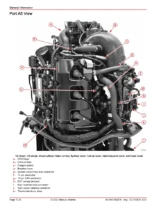
Model 50/60 (4-Stroke) Powerhead Port Viewp. 41
Model 50/60 (4-Stroke) Powerhead Top Viewp. 42
Model 50/60 (4-Stroke) Powerhead Aft Viewp. 43
Propeller Selectionp. 44
Propeller Removal/Installationp. 45
3-1/4 In. (83mm) Diameter Gear Casep. 45
4-1/4 In. (108mm) Diameter Gear Casep. 46
Power Trim Systemp. 47
General Informationp. 47
Power Trim Operationp. 47
Trim “In” Angle Adjustmentp. 48
Trim Tab Adjustmentp. 48
Compression Checkp. 49
Cylinder Leakage Testingp. 51
Analysisp. 51
Water Pressure Measurementp. 52
Painting Proceduresp. 53
Decal Applicationp. 54
Decal Removalp. 54
Instructions for ïWet” Applicationp. 54
1dp. 56
Section 1D – Outboard Motor Installationp. 56
Table of Contentsp. 56
Electric Fuel Pumpp. 56
Boat Horsepower Capacityp. 56
Start in Gear Protectionp. 57
Selecting Accessories For The Outboardp. 57
Installation Specificationsp. 57
Lifting Outboardp. 58
Steering Cablep. 58
Steering Cable Sealp. 59
Steering Link Rodp. 59
Installing Outboard – Thumb Screw Modelsp. 60
Installing Outboard – Non Thumb Screw Modelsp. 61
Wiring Harnessp. 62
Battery Cable Connectionsp. 63
Shift and Throttle Cable Installationp. 64
Shift Cable Installationp. 64
Throttle Cable Installationp. 66
Trim-In Stop Adjustment – Power Trim Modelsp. 67
Trim Tab Adjustmentp. 68
2ap. 69
Section 2A – Ignitionp. 69
Table of Contentsp. 69
Specificationsp. 70
Special Toolsp. 71
Flywheelp. 74
Electrical Componentsp. 76
Ignition Descriptionp. 78
Ignition Component Descriptionp. 78
Electronic Control Module (ECM)p. 78
Crank Position Sensorp. 79
Stator Assemblyp. 79
Flywheel Assemblyp. 80
Ignition Coilsp. 80
Ignition Test Proceduresp. 80
Ignition Troubleshootingp. 81
Ignition Diagnostic Proceduresp. 82
Recommended Testp. 83
Troubleshooting with the Digital Diagnostical Terminalp. 85
Testing Ignition Componentsp. 86
Resistance Testsp. 86
Spark Plug Cap Removalp. 87
Spark Plug Cap Resistor Test-P/N VDO5FPp. 88
Flywheel Removal and Installationp. 90
Removalp. 90
Installationp. 92
Stator Removal and Installationp. 93
Timing Belt Removal and Installationp. 94
ECM Removal and Installationp. 95
Ignition Coil Removal and Installationp. 96
Voltage Regulator Removal and Installationp. 97
Crank Position Sensor Removal and Installationp. 98
Temperature Sensor Removal and Installationp. 99
2bp. 100
Section 2B – Charging & Starting Systemp. 100
Table of Contentsp. 100
Specificationsp. 100
Special Toolsp. 101
Starter Motorp. 103
Batteryp. 104
Recommended Batteryp. 104
Operating Engine Without Batteryp. 104
Battery Charging System Troubleshootingp. 104
Battery Charging Systemp. 105
Description (15 Ampere)p. 105
Wiring Diagram (15 Ampere)p. 105
Alternator System Testp. 106
6 Ampere Statorp. 106
15 Ampere Statorp. 107
Stator Ohms Testp. 108
Regulator/Rectifier (P/N 854514-1) Diode Testp. 109
Analog Meterp. 109
Digital Meterp. 110
Starting System Componentsp. 111
Troubleshooting the Starting Circuitp. 111
Starter Solenoid Testp. 112
Starting Circuit Troubleshooting Flow Chartp. 113
Starter Motorp. 115
Removalp. 115
Disassemblyp. 115
Cleaning and Inspectionp. 117
Testingp. 118
Brush Replacementp. 120
Reassemblyp. 121
Installationp. 124
2cp. 125
Section 2C – Timing, Synchronizing, & Adjustingp. 125
Table of Contentsp. 125
Specificationsp. 125
Special Toolsp. 126
Timingp. 128
Carburetor Synchronizationp. 130
Idle Speed Adjustmentp. 134
Dashpot Adjustmentp. 135
2dp. 136
Section 2D – Wiring Diagramsp. 136
Table of Contentsp. 136
50/60 ELPTp. 137
50/60 EHPTp. 138
Commander Series Remote Control (Electric Start)p. 139
MPC 4000 Series Mechanical Panel Controlp. 140
Key Switch Testp. 141
Instrument/Lanyard Stop Switch Wiring Diagramp. 142
Instrument/Lanyard Stop Switch Wiring Diagram (Dual Outboard)p. 143
Instrument Wiring Connectionsp. 145
Oil Pressure Wiring Diagramp. 146
QSI Gauge Wiring Diagramsp. 147
Tachometer Wiring Diagramp. 147
Water Temperature Gaugep. 148
Engine Synchronizer Wiring Diagramp. 149
2 Function Gaugep. 151
Remote Wiring Harness Connection to Enginep. 152
Remote Keyp. 153
Power Trim Switch Wiring Diagramp. 154
3ap. 155
Section 3A – Fuel Pumpp. 155
Table of Contentsp. 155
Specificationsp. 155
Fuel Pumpp. 156
Fuel Pump Operationp. 158
Fuel Pump Removalp. 159
Fuel Pump Disassemblyp. 160
Cleaning/Inspection/Repairp. 161
Fuel Pump Reassemblyp. 162
Fuel Pump Installationp. 164
3bp. 165
Section 3B – Carburetorp. 165
Table of Contentsp. 165
Specificationsp. 165
Special Toolsp. 166
Fuel Linesp. 168
Carburetorp. 170
Intakep. 172
Carburetor Adjustmentsp. 173
Float Levelp. 173
Idle Speedp. 174
Idle Mixture Screw Adjustmentp. 175
Carburetor Removalp. 176
Carburetor Disassemblyp. 178
Inspectionp. 182
Carburetor Reassemblyp. 184
Carburetor Installationp. 187
3cp. 189
Section 3C – Emissionsp. 189
Table of Contentsp. 189
Exhaust Emissions Standardsp. 190
What Are Emissions?p. 190
Hydrocarbons – HCp. 190
Carbon Monoxide – COp. 190
Oxides of Nitrogen – NOxp. 190
Controlling Emissionsp. 190
Stoichiometric (14.7:1) Air/Fuel Ratiop. 191
Outboard Hydrocarbon Emissions Reductionsp. 191
Stratified Vs. Homogenized Chargep. 192
Homogenized Chargep. 192
Stratified Chargep. 193
Emissions Informationp. 194
Manufacturer s Responsibilityp. 194
Dealer Responsibilityp. 194
Owner Responsibilityp. 194
EPA Emission Regulationsp. 195
Decal Location for 2001 Modelsp. 196
Service Replacement Certification Labelp. 197
Removalp. 197
Date Code Identificationp. 197
Installationp. 197
Decal Locationp. 197
4ap. 198
Section 4A – Cylinder Headp. 198
Table of Contentsp. 198
Specificationsp. 198
Special Toolsp. 201
Cylinder Headp. 203
Camshaftp. 205
Intake/Exhaust Valvep. 207
Torque Sequencep. 209
Valve Clearance Adjustmentp. 210
Valve Cover Removalp. 210
Adjusting Valvesp. 212
Valve Cover Installationp. 215
Cylinder Head Disassemblyp. 217
Valve Cover Removalp. 217
Cylinder Head Removalp. 218
Rocker Arm Assembly Removalp. 219
Oil Pump Removalp. 219
Camshaft Removalp. 220
Valve Removalp. 221
Rocker Shaft and Rocker Armp. 222
Camshaftp. 223
Cylinder Headp. 225
Valve Guidesp. 225
Valve Guide Replacementp. 226
Valvesp. 227
Valve Springsp. 228
Valve Seat Reconditioningp. 230
Valve Refacing Stepsp. 231
Cylinder Head Reassemblyp. 232
Valve Installationp. 232
Camshaft Oil Seal Installationp. 234
Camshaft Installationp. 235
Oil Pump Installationp. 236
Rocker Arm Shaft Assemblyp. 237
Rocker Arm Shaft Installationp. 237
Cylinder Head Gasketp. 238
Cylinder Head Installationp. 239
Timing Belt Installationp. 241
Valve Cover Installationp. 242
4bp. 244
Section 4B – Cylinder Block/Crankcasep. 244
Table of Contentsp. 244
Specificationsp. 244
Special Toolsp. 245
Crankshaftp. 247
Cylinder Block and Crankcasep. 249
Torque Sequencep. 251
Powerhead Removalp. 252
Remote Control Modelp. 252
Tiller Handle Modelp. 253
Removing Powerhead Componentsp. 255
Cylinder Block Disassemblyp. 257
Inspectionp. 261
Cylinder Borep. 261
Pistonp. 262
Piston Pinp. 262
Piston Ringsp. 263
Crankshaftp. 264
Checking Main Bearing Clearancep. 265
Checking Connecting Rod Bearing Clearancep. 267
Thermostatp. 268
Oil Pressure Switchp. 268
Cylinder Block Reassemblyp. 269
Selecting New Main Bearingsp. 269
Main Bearing Installationp. 270
Selecting New Connecting Rod Bearingsp. 271
Installing Connecting Rod Bearingsp. 271
Connecting Rod Installationp. 272
Piston Ring Installationp. 273
Piston Installationp. 274
Crankshaft Installationp. 274
Crankcase Cover Installationp. 276
Exhaust Cover Installationp. 277
Drive Gear Installationp. 278
Installing Powerhead Componentsp. 279
Engine Wiring Harness and Ignition/Electrical Component Installationp. 279
Ignition Componentsp. 279
Charging and Starting System Componentsp. 279
Fuel Componentsp. 280
Powerhead Installationp. 281
Remote Control Modelp. 282
Tiller Handle Modelp. 282
Tiller Handle Modelsp. 283
4cp. 284
Section 4C – Lubricationp. 284
Table of Contentsp. 284
Specificationsp. 284
Oil Pump Removalp. 285
Oil Pump Disassemblyp. 285
Cleaning and Inspectionp. 286
Oil Pump Reassemblyp. 287
Oil Pump Installationp. 288
5ap. 289
Section 5A – Clamp/Swivel Brackets & Drive Shaft Housingp. 289
Table of Contentsp. 289
Specificationsp. 289
Swivel Bracketp. 290
Steering Armp. 292
Transom Bracketp. 294
Adaptor Platep. 296
Driveshaft Housingp. 298
Bottom Cowlp. 300
Bottom Cowl Removal/Installationp. 302
Adaptor Plate Removalp. 303
Cleaning Oil Sumpp. 307
Adaptor Plate Inspection/Cleaningp. 307
Adaptor Plate Reassemblyp. 308
Driveshaft Housing Reassemblyp. 309
5bp. 313
Section 5B – Power Trimp. 313
Table of Contentsp. 313
Special Toolsp. 314
Quicksilver Lubricants and Service Aidsp. 314
Power Trimp. 316
Theory Of Operationp. 318
Adjustmentsp. 318
Trimming Characteristicsp. 318
Trailering Outboardp. 319
Tilting Outboard Up and Down Manuallyp. 319
Power Trim Flow Diagramsp. 320
Trim Up Circuitp. 320
Tilt Circuitp. 322
Maximum Tiltp. 324
Down Circuitp. 326
Shock Function Upp. 328
Shock Function Returnp. 330
Manual Releasep. 332
Troubleshootingp. 334
Preliminary Checksp. 334
Hydraulic System Troubleshooting Flow Chartp. 335
Troubleshooting the Power Trim Electrical Systemp. 339
Power Trim System Removalp. 341
Power Trim Disassemblyp. 342
Trim Motor Removalp. 343
Pump and Components Removalp. 343
Manifold Removalp. 344
Shock Rod Removalp. 345
Shock Rod Disassemblyp. 345
Memory Piston Removalp. 348
Cleaning/Inspection/Repairp. 349
Reassemblyp. 350
O-ring Sizesp. 351
Power Trim Reassemblyp. 353
Shock Rod Reassemblyp. 353
Shock Rod Installationp. 355
Trim Limit Assembly Installationp. 356
Manual Release Valve Installationp. 356
Manifold Installationp. 357
Oil Pump Installationp. 358
Pressure Operated Assembly Installationp. 358
Reservoir/Motor Installationp. 359
Bleeding Power Trim Unitp. 360
Installation of Power Trim Systemp. 360
5cp. 364
Section 5C – Manual Tilt Assistp. 364
Table of Contentsp. 364
Special Toolsp. 364
Manual Tilt Componentsp. 365
Manual Trim Flow Diagramsp. 367
Up Circuitp. 367
Down Circuitp. 369
Slow Tilt Down Under High Thrustp. 371
Under Water Strike (Valves Open)p. 373
Shock Function (Valve Closed)p. 375
Shock Function Returnp. 377
Hydraulic System Troubleshootingp. 379
Manual Tilt System Removalp. 381
Manual Tilt System Disassemblyp. 382
Accumulator Removalp. 383
Shock Rod Removalp. 384
Shock Rod Disassemblyp. 384
Valve Block Removalp. 387
Memory Piston Removalp. 387
Valve Block Disassemblyp. 389
Reassembly – O-Ring and Seal Placementp. 390
Actual O-Ring Sizesp. 391
O-Ring Description and Sizesp. 392
Manual Tilt System Cleaning and Inspectionp. 392
Manual Tilt System Reassemblyp. 392
Valve Block Installationp. 395
Shock Rod Reassemblyp. 396
Shock Rod Installation and Fluid Filling Procedurep. 398
Filling Procedure Option Two Instructions for Making Retaining Toolp. 400
Bleeding Manual Tilt Systemp. 401
Manual Tilt System Installationp. 403
Manual Release Valve Adjustmentp. 405
6ap. 406
Section 6A – Non-Bigfoot Gear Housingp. 406
Table of Contentsp. 406
Specificationsp. 406
Special Toolsp. 407
Quicksilver Lubricants and Service Aidsp. 410
Gear Housing (Drive Shaft)(1.83:1 Gear Ratio)p. 411
Gear Housing (Prop Shaft)(1.83:1 Gear Ratio)p. 413
General Service Recommendationsp. 415
Bearingsp. 415
Sealsp. 415
Draining and Inspecting Gear Lubricantp. 416
Removalp. 417
Disassemblyp. 418
Water Pumpp. 418
Bearing Carrier and Propeller Shaftp. 420
Propeller Shaft Disassemblyp. 423
Pinion Gear, Driveshaft and Forward Gearp. 425
Upper Driveshaft Bearingp. 426
Lower Driveshaft Bearingp. 427
Forward Gear Bearing Racep. 427
Shift Shaftp. 428
Gear Housing Reassemblyp. 430
Shift Shaftp. 430
Propeller Shaftp. 431
Forward Gear Bearing Racep. 433
Bearing Carrierp. 433
Reverse Gearp. 436
Forward Gearp. 437
Lower Driveshaft Bearing Installationp. 438
Upper Driveshaft Bearing Installationp. 439
Forward Gear, Pinion Gear, Upper Driveshaft Bearing Race, Retainer and Driveshaft Installationp. 440
Pinion Gear Location and Forward Gear Backlashp. 441
Determining Forward Gear Backlashp. 444
Bearing Carrier and Propeller Shaft Installationp. 446
Water Pump Re-assembly and Installationp. 447
Gear Housing Pressure Testp. 452
Gear Housing Installationp. 453
Filling Gear Housing with Lubricantp. 455
Trim Tab Adjustment and Replacementp. 456
6bp. 457
Section 6B – Bigfoot Gear Housingp. 457
Table of Contentsp. 457
Specificationsp. 457
Special Toolsp. 458
Quicksilver Lubricants and Service Aidsp. 461
Gear Housing (Drive Shaft)(2.31:1 Gear Ratio)p. 462
Gear Housing (Prop Shaft)(2.31:1 Gear Ratio)p. 464
General Service Recommendationsp. 466
Draining and Inspecting Gear Lubricantp. 467
Removalp. 468
Disassemblyp. 469
Water Pumpp. 469
Bearing Carrier and Propeller Shaftp. 472
Pinion Gear, Drive Shaft, and Forward Gearp. 477
Upper Drive Shaft Bearingp. 480
Oil Sleevep. 481
Lower Drive Shaft Bearing Racep. 482
Shift Shaftp. 483
Forward Gear Bearing Racep. 485
Trim Tab Adjustment and Replacementp. 485
Reassemblyp. 486
Forward Gear Bearing Racep. 486
Shift Shaftp. 486
Bearing Carrier Reassemblyp. 489
Forward Gear Reassemblyp. 493
Propeller Shaft Reassemblyp. 495
Drive Shaft Wear Sleeve Installationp. 496
Lower Drive Shaft Bearing Race Installationp. 498
Oil Sleeve Installationp. 499
Upper Drive Shaft Bearing Installationp. 499
Forward Gear, Lower Drive Shaft Bearing, Pinion Gear, and Drive Shaft Installationp. 501
Pinion Gear Depth and Forward Gear Backlashp. 502
Bearing Carrier and Propeller Shaft Installationp. 507
Water Pump Reassembly and Installationp. 509
Gear Housing Pressure Testp. 512
Filling Gear Housing With Lubricantp. 513
Gearcase Installationp. 514
Trim Tab Adjustmentp. 518
7ap. 519
Section 7A – Throttle/Shift Linkagep. 519
Table of Contentsp. 519
Linkage (Remote)p. 520
Linkage (Handle)p. 522
7bp. 524
Section 7B – Tiller Handlep. 524
Table of Contentsp. 524
Tiller Handlep. 525
Tiller Handle Assembly Removalp. 527
Tiller Handle Disassemblyp. 529
Cleaning/Inspection/Repairp. 531
Tiller Handle Reassemblyp. 532
Tiller Handle Installationp. 537
8p. 542
COLOR DIAGRAMSp. 542
Table of Contentsp. 542
50/60 (4-Stroke) Tiller Handle Electric Color Wiring Diagram 2001 Modelsp. 544
50/60 (4-Stroke) Remote Control Electric Color Wiring Diagram 2001 Modelsp. 547
MPC 4000 Mechanical Panel Control Color Wiring Diagramp. 550


IMAGES PREVIEW

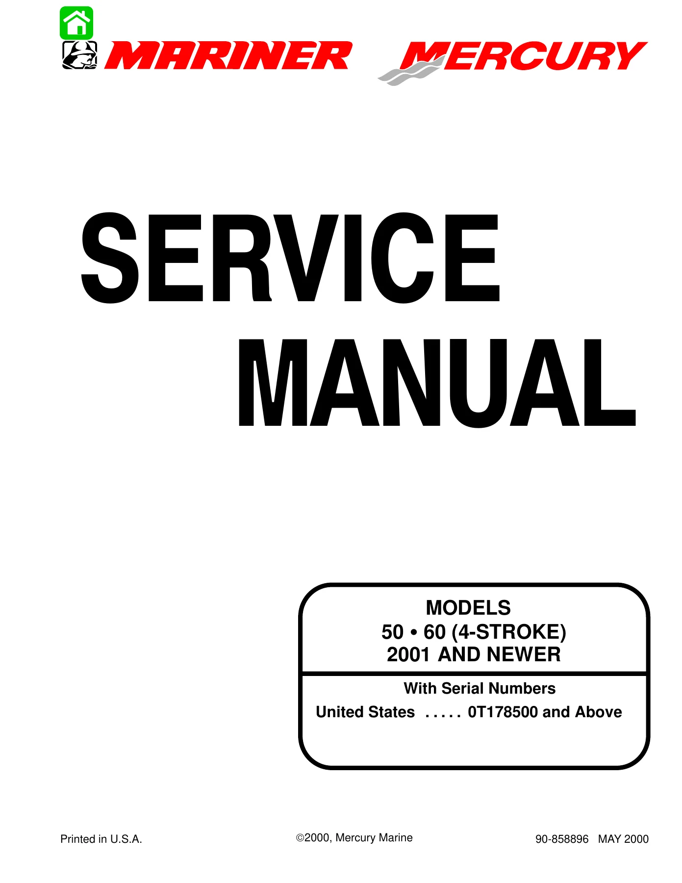
2001 & Newer Mercury Mariner 50 60 HP 4-Stroke Outboard Service Manual — PDF page 1 preview
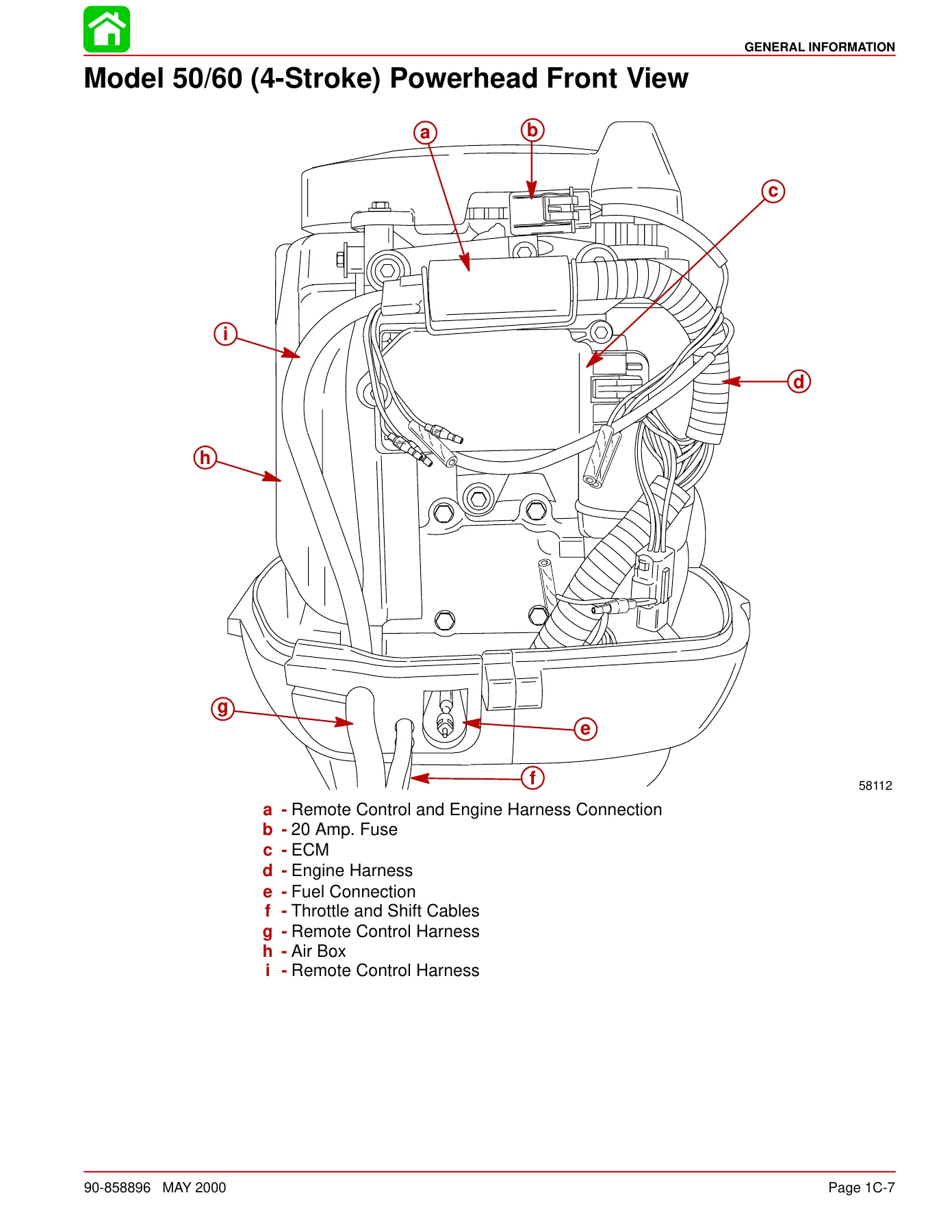
2001 & Newer Mercury Mariner 50 60 HP 4-Stroke Outboard Service Manual — PDF page 39 preview
2001 & Newer Mercury Mariner 50 60 HP 4-Stroke Outboard Service Manual — PDF page 547 preview

Instant PDF Delivery

This Mercury Mariner 50/60 HP FourStroke outboard repair manual is delivered as an instant PDF download — no shipping, no waiting for a physical book to arrive. Once your order is complete, you can access the file immediately and view it on any device: desktop, laptop, tablet, or smartphone. Print the pages you need for the job at hand, keep the full manual on a shop computer, or load it onto a tablet for reference at the dock. The PDF format lets you work with the manual the way that suits your workspace best.
Reviews

There are no reviews yet.

Be the first to review “2001 & Newer Mercury Mariner 50 60 HP 4-Stroke Outboard Service Manual”

What Our Customers Say

★★★★★ Live reviews from customers
Loading customer reviews...
0
    0
    Your Cart
    Your cart is emptyReturn to Shop
    🛒
    Recently Purchased
    🕒 verified order