
2013 SANY SY305H Hydraulic Excavator Maintenance Service Manual PDF
Original price was: $39.95.$23.95Current price is: $23.95.
Complete 590-page maintenance and service reference for the SANY SY305H hydraulic excavator, covering specifications, system structure and operation, standard values, testing and adjustment, troubleshooting, removal and refitting procedures, plus hydraulic and electrical diagrams.
Description
2013 SANY SY305H Hydraulic Excavator Maintenance Service Manual PDF
This detailed workshop reference is designed for experienced technicians and provides comprehensive maintenance, inspection, testing, diagnosis, repair, removal and refitting work on the SY305H hydraulic excavator. Spanning 590 pages, this manual combines machine specifications with system explanations, standard service values, test procedures, fault-diagnosis information and component-level service procedures. Its coverage follows the machine from the ISUZU engine and hydraulic powertrain through the undercarriage, work equipment, HVAC, electrical controls, display system and final hydraulic/electrical diagrams.
File Details
- Manual type: Maintenance Manual / Service Manual
- Brand: SANY
- Model: SY305H Hydraulic Excavator
- Language: English
- Pages: 590
- File format: PDF
- Manual date: 05-2013
Built Around the SY305H Service Workflow
This 2013 SANY SY305H Hydraulic Excavator Maintenance Service Manual PDF is not limited to routine maintenance notes. It develops the technical background needed to understand how the machine is built and how its systems operate, then connects that information to inspection values, measurements, adjustments, troubleshooting and disassembly/reassembly work.
The manual explains standard dimensions, clearances, repair limits and allowable values before moving into component specifications and field service procedures, so measurements can be compared against stated service criteria rather than judged by appearance alone.
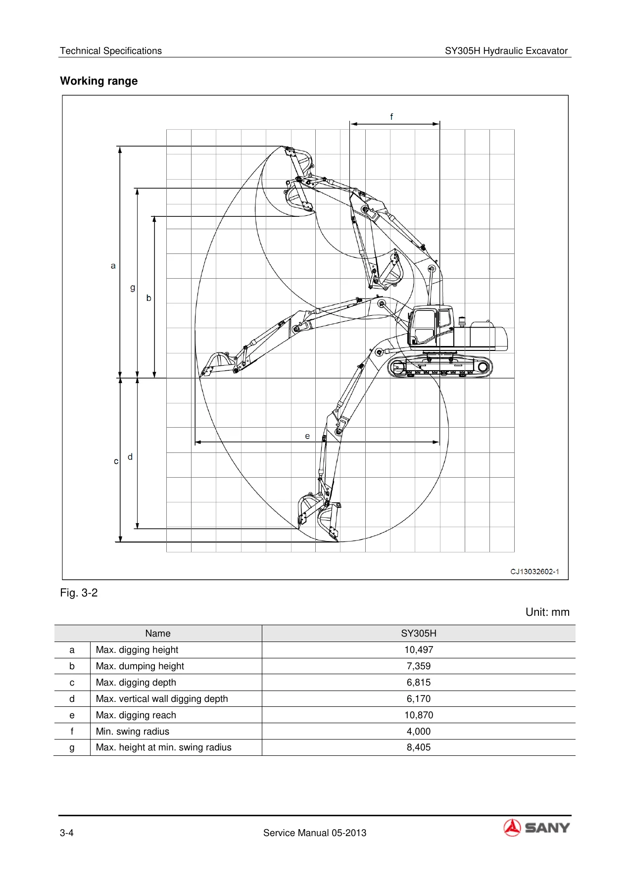
The technical specification material identifies the SY305H as a 31,500 kg machine with a 1.7 m³ bucket capacity and gives machine dimensions, working range, digging forces, travel and swing performance, ground pressure and other operating parameters.
The engine section identifies the ISUZU 6HK1-XDHAG-01-C3, with detailed information on its common-rail fuel system, lubrication, cooling, electrical starting and charging systems, sensors and engine control.
Hydraulic data includes the variable-displacement main pump arrangement, control valve information, relief pressures, hydraulic motor and cylinder information, hydraulic tank details and circuit operation.
System Structure, Principles and Service Data
A major part of the manual is devoted to structure and function. This section uses sectional drawings, component layouts and hydraulic schematics to show how major assemblies work before service begins.
It covers the engine and powertrain, travel reducer, swing reducer and swing bearing, track frame and undercarriage components, hydraulic pumps and regulators, the multi-way control valve, swing and travel motors, pilot controls, hydraulic cylinders and work equipment.
It also develops the HVAC system, engine-control functions, electrical control functions and the display system.
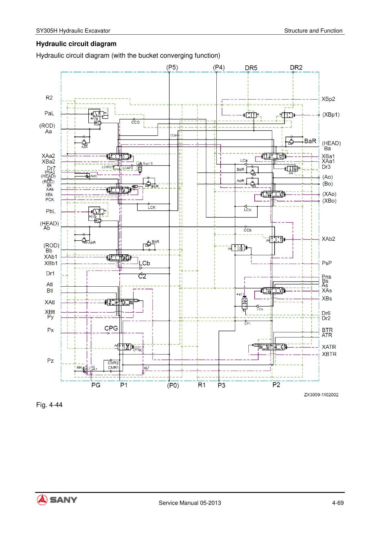
For hydraulic diagnosis and adjustment, the manual follows oil flow through boom, arm, bucket, swing, travel and straight-travel circuits. It explains relief-valve and locking-valve operation, pump flow control, power control, regulator adjustments, swing retention braking, travel braking and other functions.
These explanations are especially useful when a pressure or movement problem cannot be resolved by replacing parts alone, because the technician can trace the intended operating principle alongside the test and troubleshooting information.
Chapters Covered
- 1. Foreword and Introduction
- How to read this manual; maintenance-standard terminology
- Treatment of electrical and hydraulic components
- Pipe connectors, O-rings and tightening torques
- Standard bolt and split-flange tightening information; conversion tables
- 2. Safety
- Safety decals, signal terms and general workshop precautions
- Preparations before maintenance and warning procedures
- High-pressure fluid, hot coolant, HVAC and electrical safety
- Battery, accumulator, fire prevention, waste disposal and hoisting precautions
- 3. Technical Specifications
- Machine dimensions and working range
- Technical specifications and component weight table
- Engine oil, fuel, coolant and engine performance graph
- 4. Structure and Function
- Engine, powertrain, travel reducer, swing reducer, swing bearing and lower structure
- Hydraulic system layout, tank, main pump, pilot pump and regulator
- Control valve circuits, boom/arm/bucket/swing/travel operation, relief and locking valves
- Swing motor, travel motor, pilot control, solenoid valves, cylinders and work equipment
- HVAC group, engine control, electrical control system and display system
- 5. Standard Values of Components
- Standard values and maintenance limits for engine-related components
- Body-related values for engine speed, control operation, hydraulic pressure, swing, travel and work equipment
- 6. Test and adjustment
- Engine speed, exhaust smoke, EGR, compression pressure and lubrication-system checks
- A/C compressor belt, swing bearing and track tension inspection/adjustment
- Work-equipment, swing, travel and control oil-pressure checks
- Solenoid-valve and pilot-valve output pressure measurement
- Hydraulic-cylinder drift, residual-pressure release, leakage measurement and air bleeding
- 7. Fault Diagnosis and Troubleshooting
- Precautions, preliminary inspection and fault-diagnosis steps
- Connector tables, connector positions and system circuit diagrams
- Diagnosis using displayed DTC information
- Electrical-system fault diagnosis
- Hydraulic and mechanical system fault diagnosis
- 8. Removal and refitting
- Radiator, engine/hydraulic pump, final drive, swing motor and swing mechanism
- Idler, drive wheel, track, swing bearing, turntable and center swivel joint
- Hydraulic tank, control valve, hydraulic pump, pilot valves and hydraulic cylinders
- Work equipment, HVAC, counterweight, cab, windows and front window assembly
- Display, controller, radio, battery, ignition switch, fuse box, wiper, relays and terminals
- 9. Hydraulic and Electrical Diagrams
- Hydraulic lines diagram
- HVAC, control switch, display screen, cab and body electrical diagrams
Taken together, these chapters give a technician both reference values and the procedures needed to use them. The standard-values chapter supplies baseline and allowable figures for service judgments, while the test-and-adjustment chapter explains how to take measurements under defined conditions.
The troubleshooting chapter then organizes diagnosis around observed symptoms, connectors, circuits, DTCs and system categories, and the removal/refitting chapter provides step-by-step access to major assemblies once repair work is required.
Useful Detail for Engine, Hydraulic and Undercarriage Work
The engine material goes beyond basic identification. It includes specifications for bore and stroke, displacement, compression, valve clearance, lubrication and cooling, plus common-rail components, sensors and electronic control functions.
Separate diagrams show the fuel path and key engine components, while inspection and troubleshooting sections provide service-oriented checks. The manual also includes tightening practices for pipe connectors, O-rings, bolts and split flanges, helping keep assembly work consistent with the values given in the manual.
Hydraulic coverage is equally extensive. The SY305H main hydraulic system is broken down into pump, regulator, control valve, pilot circuit, swing, travel and work-equipment functions.
Circuit diagrams and sectional illustrations show how oil is routed during boom lifting and lowering, arm extension and retraction, bucket digging and dumping, swing, travel and combined operations. Service information also covers hydraulic-tank capacity, pump flow, relief settings, cylinder data, pressure checks, leakage measurement and residual-pressure release.
IMAGES PREVIEW
This makes the manual useful for both mechanical repair and performance diagnosis.
Undercarriage and drive information includes the track frame, tension mechanism, idler, carrier roller, track roller, crawler components, travel reducer, swing reducer and swing bearing. Standard sizes, clearances, limits and component weights appear throughout the manual where applicable.
Removal and refitting procedures then cover major assemblies such as the final drive, track assembly, swing bearing, turntable and center swivel joint.
Electrical, Controls and HVAC Coverage
The manual treats electrical diagnosis as part of the complete machine service process. It explains connector handling, controller precautions and circuit-diagnosis practices, then develops engine sensors, solenoid valves, electrical control functions and display-system information.
The troubleshooting section contains connector and circuit references and separates electrical fault diagnosis from hydraulic/mechanical diagnosis. The final chapter adds dedicated electrical diagrams for the HVAC group, control switch, display screen, cab and body.
HVAC information includes system layout and operating principles together with compressor, clutch, condenser, expansion valve, evaporator, dryer, pressure switch, sensors, refrigerant and compressor-oil information.
Safety sections specifically identify R134a refrigerant and precautions for electrical, pressure and thermal hazards encountered during service.
Get the SY305H Repair Information in One PDF
The 2013 SANY SY305H Hydraulic Excavator Maintenance Service Manual PDF supports a wide range of workshop jobs: checking machine and engine performance, comparing measured values with service limits, testing hydraulic pressures, tracing electrical or hydraulic faults, adjusting systems, diagnosing DTC-related problems, and removing, disassembling, reassembling or refitting major components.
Its combination of procedures, specifications, standard values, sectional drawings and hydraulic/electrical diagrams helps technicians work from defined information instead of guesswork, particularly when correct pressures, clearances, torques and test conditions matter.
After payment, the manual is supplied as an instant PDF download with no physical shipping. You can open it on a compatible phone, tablet or computer and print the pages you need for workshop use.

Reviews
There are no reviews yet.