★ TRUSTED BY 321,897+ PROFESSIONALS WORLDWIDE
🏒
Trusted Business
Verified & Licensed
πŸ›‘οΈ
Virus Free Files
100% Safe Downloads
πŸ”’
Secure Payment
SSL Protected
⚑
Instant Delivery
Available Immediately
Sale!

2024 CFMOTO CFORCE 400 450 500 520 Service Manual – Full Workshop Repair PDF

Original price was: $34.95.Current price is: $19.95.

Complete 358-page CFMOTO service manual for the 2024 CFORCE 400, 450, 500 and 520 – engine, CVT, EFI, brakes, suspension, steering, cooling, electrical and full wiring diagrams.

⚑
Instant PDF Download
Available immediately
πŸ’Ύ
Save to Your Device
Download & keep forever
πŸ›‘οΈ
Antivirus Scanned
100% virus-free
🌍
Trusted Worldwide
175,000+ customers

Description

File Details

  • Manual type: Service / Workshop Manual
  • Brand: CFMOTO
  • Models covered: CF400AU-3S/3L, CF400AZ-3S/3L, CF400ATR-3S/3L, CF500AU-9S/9L, CF500AZ-9S/9L, CF500ATR-9S/9L (CFORCE 400 / 450 / 500 / 520)
  • Language: English
  • Page count: 358
  • File format: PDF
  • Edition No.: 20230901
  • Edition item: (9DQV-WX-01-2)SM-20230901

Chapters Covered

  • Safety Information – service manual notes, safety tips, hazardous level symbols, general precautions, removal and installation cautions, engine break-in, warranty, fuel/engine oil/coolant, caption
  • Specifications / Vehicle Data – unit conversion tables and symbols, identification number locations, main specifications, service specifications, fastener torque tables, engine component torque table, engine service tools
  • Maintenance – maintenance schedule, maintenance before operation, break-in maintenance checklist, periodic maintenance schedule
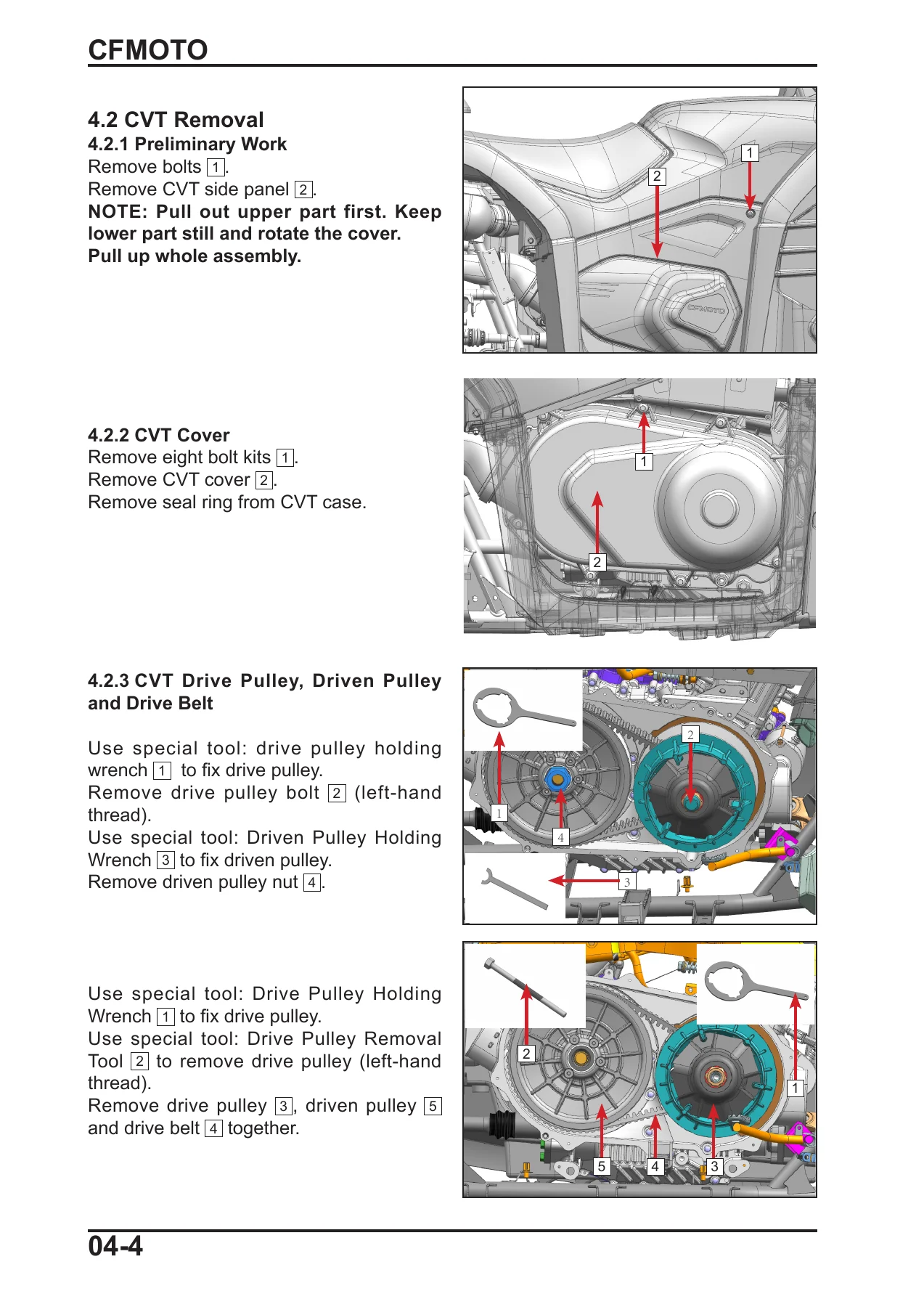
  • CVT System – special tools, CVT removal, CVT parts inspection, CVT installation
  • Engine – special tools, engine removal, air intake and exhaust system, engine disassembly, engine parts inspection, engine assembly, engine installation, cooling system, lubrication system, fuel system
  • Body and Frame – seat, battery, front and rear rack, front service cover, CVT side cover, handlebar guard, fuel tank guard, engine LH cover, fenders, headlight guards, foot boards, front fender, rear fender, dashboard guard, vehicle skid plate
  • Powertrain – gear cases, CV drive shaft, front gear case, rear gear case (differential), rear gear case (non-differential), drive shaft
  • Brake System – brake assembly, brake fluid, mechanical parking brake, hydraulic parking brake
  • Suspension System – tires, wheel toe-in, front shock absorber, rear shock absorber, front suspension, rear suspension, sway bar
  • Steering – handlebar, steering feature (non-EPS), steering feature (EPS), EPS failure code table, gear shift assembly
  • Cooling and Heating System – cooling system, radiator assembly, radiator deco guard, reservoir tank, fan motor, radiator, radiator fan inspection, cooling system sealing, coolant
  • Electrical – diagnosis tool, signal and illumination system, earth wire inspection, fuse box, lights, horn, winch control switch, alarm, switches, T-BOX, charging system, EFI system, EFI parts, EFI self-diagnosis, fault diagnosis, fault code tables (MSE 6.0 / MSE 8.0 / T-BOX / DASH)
  • Appendix A – EFI Diagram
  • Appendix B – Electrical Schematic Diagram

This 2024 CFMOTO CFORCE 400 450 500 520 Service Manual is the complete workshop reference for the CF400AU, CF400AZ, CF400ATR, CF500AU, CF500AZ and CF500ATR variants, written for the technician who has to take the machine apart, measure it, put it back together and have it run right. It opens with safety information and general precautions, then moves through vehicle and engine specifications, torque tables and the engine service tools needed before any spanner is turned. From there it works system by system: the CVT drive and driven pulleys, the complete engine including cylinder head, camshaft, valves, piston, crankshaft, timing chain, oil pump and water pump, the air intake and exhaust system, the lubrication and cooling circuits, and the fuel system. Chassis coverage follows with body and frame panels, racks and covers, then the full powertrain chapter covering the front and rear gear cases, differential assemblies, CV drive shafts and drive shaft inspection. Brakes, suspension, steering and the EPS system each get their own chapter with removal, inspection, assembly and adjustment procedures, and the electrical chapter carries battery and charging checks, fuse box layout, lighting, switches, T-BOX diagnostics and the complete EFI section with sensor and actuator testing.

What This Workshop Manual Covers In Practice

Every procedure in this CFMOTO CFORCE 500 and CFORCE 400 service manual is presented with the removal sequence, the inspection criteria and the installation torque, so a job can be planned and finished in one pass rather than guessed at. Engine work is covered down to component level: cylinder head disassembly and inspection, camshaft and rocker arm measurement, valve clearance adjustment, piston and piston ring clearance checks, cylinder bore measurement, connecting rod and crankshaft inspection for both the 191Q and 191R engine variants, and the shim adjustment procedure for drive and driven bevel gear backlash and tooth contact. The CVT chapter walks through pulley disassembly with the correct holding wrenches, drive belt wear limits, weight slider and ramp slider inspection, and the driven pulley spring and cam plate checks, which is where a lot of CFORCE performance complaints actually originate.

The steering, brake and suspension chapters are equally practical for a CFORCE 450 or CFORCE 520 owner. Non-EPS and EPS steering systems are handled separately, with the EPS connector pinout, the failure code table with a diagnosis and solution for each code, and a troubleshooting chart for no-assist, uneven assist, heavy steering and system noise. Brake work includes pad and disc thickness limits, brake fluid replacement and bleeding, plus the mechanical and hydraulic parking brake adjustment procedures. Suspension coverage includes wheel toe-in measurement and adjustment, shock absorber spring preload adjustment, and front and rear swing arm removal with bushing and ball joint inspection.

Complete PDF Bookmark Tree

Complete Bookmarks

The complete bookmarks in the β€œ2024 CFMOTO CFORCE 400 450 500 520 Service Manual – Full Workshop Repair PDF” are as follows:

01 Safety Informationp. 4
1.1 Service Manualp. 5
1.2 Safety Tipsp. 5
1.3 Hazardous Level and Symbolp. 5
1.4 Operation Noticep. 5
1.5 General Precautionp. 6
1.5.1 Avoid Carbon Monoxide Poisoningp. 6
1.5.2 Avoid Corrosion Injury by Electrolytep. 6
1.5.3 Avoid Injuryp. 6
1.5.4 Avoid Scaldp. 6
1.5.5 Avoid Toxic Coolantp. 6
1.5.6 Avoid Explode and Firep. 7
1.5.7 Operational Safetyp. 7
1.6 Cautions for Removal and Installationp. 7
1.7 Engine Break-inp. 9
1.8 Warrantyp. 9
1.9 Fuel, Engine Oil and Coolantp. 9
1.10 Captionp. 9
02 General Informationp. 10
2.1 Unit conversion tables and symbols used in this manualp. 11
2.2 Identification Number Locationsp. 12
2.3 Main Specificationsp. 13
2.3.1 Vehiclep. 13
2.3.2 Engine Specificationp. 14
2.4 Specifications for Servicep. 17
2.4.1 Fastener Torque Tablesp. 24
2.4.2 Torque Table – Engine Componentsp. 25
2.4.3 Engine Service Toolsp. 29
03 Maintenancep. 30
3.1 Maintenance Schedulep. 31
3.1.1 Maintenance before operationp. 31
3.1.2 Break-In Maintenance Checklistp. 33
3.1.3 Periodic Maintenance Schedulep. 34
04 CVT Systemp. 37
4.1 CVT Special Toolp. 38
4.2 CVT Removalp. 40
4.2.1 Preliminary Workp. 40
4.2.2 CVT Coverp. 40
4.2.3 CVT Drive Pulley, Driven Pulley and Drive Beltp. 40
4.3 CVT Parts Inspectionp. 41
4.3.1 CVT Cover Assyp. 41
4.3.2 Drive Beltp. 42
4.3.3 Drive Pulleyp. 42
4.3.4 Driven Pulleyp. 45
4.4 CVT Installationp. 48
4.4.1 Drive Pulley, Driven Pulley and Drive Belt Assemblyp. 48
4.4.2 Drive Pulley, Driven Pulley and Drive Belt Installationp. 49
4.4.3 CVT Cover Installationp. 49
05 Enginep. 51
5.1 Special Tools for Enginep. 56
5.2 Engine Removalp. 66
5.2.1 Shift Lever Removalp. 66
5.2.2 Drive Shaft Removalp. 66
5.2.3 Coolant Drainp. 67
5.2.4 Engine Oil Drainp. 68
5.2.5 Enginep. 68
5.3 Air Intake&Exhaust Systemp. 70
5.3.1 Air Filter Removalp. 70
5.3.2 Air Filter Parts Inspectionp. 72
5.3.2.1 Air Filter Upper Housingp. 72
5.3.2.2 Air Filter Lower Housing Assemblyp. 73
5.3.2.3 Air Filter Elementp. 74
5.3.3 Air Filter Installationp. 75
5.3.4 Engine Air Intake Pipep. 78
5.3.4.1 Removalp. 78
5.3.4.2 Parts Inspectionp. 79
5.3.4.3 Installationp. 80
5.3.5 Air Exhaust Systemp. 82
5.3.5.1 Removalp. 82
5.3.5.2 Inspectionp. 85
5.3.5.3 Installationp. 86
5.4 Engine Disassemblyp. 89
5.4.1 Engine Oil Drainp. 89
5.4.2 CVT Case ASSyp. 89
5.4.3 PTO Crankcase Cover Assyp. 90
5.4.4 Cylinder Head Cover Removalp. 91
5.4.5 TDC Adjustmentp. 91
5.4.6 Tensionerp. 92
5.4.7 Cylinder Headp. 92
5.4.8 Oil Filterp. 93
5.4.9 Gearshift Assemblyp. 94
5.4.10 Water Pumpp. 94
5.4.11 Starter Motorp. 95
5.4.12 MAG Crankcase Cover (191Q)p. 95
5.4.13 MAG Crankcase Cover (191R)p. 96
5.4.14 Magneto Rotorp. 97
5.4.15 Oil Pumpp. 98
5.4.16 Timing Chainp. 99
5.4.17 Cylinder Bodyp. 99
5.4.18 Crankcase Bodyp. 100
5.4.19 Crankshaft Assembly and Balance Shaftp. 100
5.4.20 Drive Bevel Gear Assembly,p. 101
5.5 Engine Parts Inspectionp. 102
5.5.1 Cylinder Head Coverp. 102
5.5.2 Cylinder Headp. 102
5.5.3 Cylinder Bodyp. 110
5.5.4 Timing Chain Tensionerp. 111
5.5.5 Pistonp. 111
5.5.6 Timing Chainp. 113
5.5.7 Tension Plate, Chain Guide and Chain Guardp. 114
5.5.8 Shift Gear Assemblyp. 114
5.5.9 Gearshift Coverp. 114
5.5.10 Water Pump Assemblyp. 115
5.5.11 Relief Valvep. 119
5.5.12 Oil Filter Elementp. 120
5.5.13 Overriding Clutchp. 120
5.5.14 Magneto Rotorp. 121
5.5.15 Magneto Statorp. 121
5.5.16 Starter Dual Gearp. 122
5.5.17 Oil Pump Drive Gear and Oil Pump Dual Gearp. 122
5.5.18 Oil Pump Assemblyp. 122
5.5.19 Crankshaft And Connecting Rod Inspection (191Q)p. 123
5.5.20 Crankshaft And Connecting Rod Inspection (191R)p. 127
5.5.21 Balance Shaftp. 129
5.5.22 Main Shaftp. 129
5.5.23 Counter Shaft Assemblyp. 130
5.5.24 Shift Drump. 130
5.5.25 Shift Fork Assemblyp. 131
5.5.26 Parking Swing Armp. 132
5.5.27 Reverse Intermediate Gearp. 133
5.5.28 Drive Bevel Gear Assyp. 134
5.5.29 Front Output Shaftp. 136
5.5.30 Driven Bevel Gearp. 137
5.5.31 MAG Crankcase Coverp. 140
5.5.32 MAG Crankcasep. 141
5.5.33 Oil Strainer and Oil Trail Cover Platep. 143
5.5.34 Speed Sensorp. 145
5.5.35 PTO Crankcasep. 145
5.5.36 Gear Sensor and Oil Pressure Switchp. 147
5.5.37 CVT Case Assyp. 148
5.5.38 PTO Crankcase Cover Assyp. 148
5.6 Engine Assemblyp. 151
5.6.1 Shifting Mechanismp. 151
5.6.1.1 Shim Adjustment Procedurep. 152
5.6.2 Crankshaft Connecting Rod and Balance Shaftp. 157
5.6.3 Crankcase Assemblyp. 157
5.6.4 Pistonp. 158
5.6.5 Cylinder Bodyp. 159
5.6.6 Shift Sector Gearp. 160
5.6.7 Oil Pumpp. 160
5.6.8 Starter Dual Gearp. 161
5.6.9 Magneto Stator (191Q)p. 161
5.6.10 Magneto Stator (191R)p. 162
5.6.11 MAG Crankcase Cover (191Q)p. 163
5.6.12 MAG Crankcase Cover (191R)p. 164
5.6.13 Timing Chainp. 164
5.6.14 Cylinder Headp. 165
5.6.15 TDC Adjustmentp. 165
5.6.16 Timing Sprocketp. 165
5.6.17 Valve Clearance Adjustmentp. 166
5.6.18 Timing Chain Tensionerp. 166
5.6.19 Cylinder Head Coverp. 166
5.6.20 Starter Motorp. 167
5.6.21 Oil Filterp. 167
5.6.22 Water Pump Coverp. 167
5.6.23 Magneto End Cap and Crankshaft Position Sensorp. 168
5.6.24 Oil Dipstick, Drain Bolt and Speed Sensorp. 168
5.6.25 Spark Plugp. 169
5.6.26 PTO Crankcase Cover Assyp. 169
5.6.27 CVT Case Assyp. 169
5.7 Engine Installationp. 171
5.8 Cooling Systemp. 174
5.8.1 Cooling System Viewp. 174
5.8.2 Coolant Replacementp. 175
5.8.3 Thermostat and Water Pumpp. 176
5.9 Lubrication Systemp. 177
5.9.1 Lubrication System Viewp. 177
5.9.2 Engine Oil Capacity Inspectionp. 178
5.9.3 Engine Oil Replacementp. 178
5.9.4 Oil Filter Element Replacementp. 179
5.9.5 Engine Oil Pressure Inspectionp. 179
5.9.6 Relief Valve, Oil Pump and Oil Strainerp. 180
5.10 Fuel Systemp. 181
5.10.1 Fuel Tankp. 181
5.10.2 Inspectionp. 184
5.10.3 Installationp. 185
06 Vehicle and Body Covering Partsp. 188
6.1 Maintenance Informationp. 189
6.2 Seatp. 190
6.3 Batteryp. 190
6.4 Rackp. 191
6.4.1 Front Rackp. 191
6.4.2 Rear Rackp. 191
6.5 Front Service Coverp. 192
6.6 CVT Side Coverp. 192
6.7 Handlebar Guardp. 192
6.8 Fuel Tank Guardp. 193
6.9 Engine LH Coverp. 194
6.10 Fendersp. 195
6.10.1 LH Front Fenderp. 195
6.10.2 RH Front Fenderp. 195
6.11 Headlight Guardsp. 196
6.11.1 LH Headlight Guardp. 196
6.11.2 RH Headlight Guardp. 196
6.12 Foot Boardsp. 197
6.12.1 LH Foot Boardp. 197
6.12.2 RH Foot Boardp. 199
6.13 Front Fenderp. 201
6.13.1 Front Lower Platep. 201
6.13.2 Headlight Panel Gridp. 201
6.13.3 Headlight Panelp. 201
6.14 Rear Fenderp. 204
6.15 Dashboard Guardp. 205
6.16 Vehicle Skid Platep. 206
6.16.1 Engine Front Panelp. 206
6.16.2 Engine Middle Panelp. 206
6.16.3 Engine Rear Panelp. 206
07 Powertrainp. 207
7.1 Gear Casesp. 208
7.1.1 Maintenance Informationp. 208
7.1.2 Inspection and Maintenancep. 208
7.2 CV Drive Shaftp. 209
7.3 CV Drive Shaft Inspection and Maintenancep. 209
7.3.1 CV Drive Shaft Inspectionp. 209
7.3.1.1 Shaft Cage Dust Bootp. 210
7.4 Front Gear Casep. 211
7.4.1 Front Gear Case Removalp. 211
7.4.2 Front Gear Case Disassemblyp. 212
7.4.3 Front Gear Case Input Shaft Assemblyp. 214
7.4.4 Differential Assemblyp. 215
7.4.5 Front Gear Case Inspectionp. 216
7.4.6 Front Gear Case Assemblyp. 221
7.5 Rear Gear Case (Differential)p. 225
7.5.1 Rear Gear Case Removalp. 225
7.5.2 Rear Gear Case Disassemblyp. 227
7.5.3 Rear Gear Case Input Shaftp. 227
7.5.4 Differential Assemblyp. 228
7.5.5 Rear Gear Case Inspectionp. 230
7.5.6 Rear Gear Case Assemblyp. 234
7.5.7 Rear Gear Case Installationp. 240
7.6 Rear Gear Case(Non-differential)p. 241
7.6.1 Rear Gear Case Removalp. 241
7.6.2 Rear Gear Case Disassemblyp. 242
7.6.3 Rear Gear Case Input Shaft Assemblyp. 243
7.6.4 Driven Bevel Gear Assemblyp. 244
7.6.5 Rear Gear Case Inspectionp. 244
7.6.6 Rear Gear Case Assemblyp. 245
7.7 Drive Shaftp. 249
08 Brake Systemp. 250
8.1 Brake Assemblyp. 251
8.1.1 Brake Removalp. 251
8.1.2 Brake Inspectionp. 253
8.2 Brake Fluidp. 254
8.3 Parking Brakep. 256
8.3.1 Mechanical Parking Brakep. 256
8.3.2 Hydraulic Parking Brakep. 258
09 Suspensionp. 259
9.1 Tirep. 260
9.1.1 Wheel Toe-inp. 262
9.2 Shock Absorbersp. 263
9.2.1 Front Shock Absorberp. 263
9.2.2 Rear Shock Absorberp. 264
9.3 Front Suspensionp. 265
9.4 Rear Suspensionp. 267
9.4.1 Sway Barp. 268
10 Steering Systemp. 269
10.1 Handlebarp. 270
10.2 Steering Systemp. 270
10.2.1 Steering Feature (Non-EPS)p. 270
10.2.2 Steering Feature (EPS)p. 272
10.3 EPSp. 274
11 Cooling Systemp. 280
11.1 Cooling Systemp. 281
11.2 Radiator Assemblyp. 282
11.2.1 Radiator Deco Guardp. 282
11.2.2 Reservoir Tankp. 283
11.2.3 Fan Motorp. 283
11.2.4 Radiatorp. 283
11.3 Radiator Fan Inspectionp. 285
11.4 Cooling System Sealingp. 287
11.5 Coolantp. 288
12 Electrical Systemp. 289
12.1 Diagnosis Toolp. 291
12.2 Signal and Illumination Systemp. 292
12.2.1 Batteryp. 292
12.2.2 Charging Voltage Inspectionp. 293
12.3 Earth Wire Inspectionp. 293
12.4 Fuse boxp. 294
12.5 Light Maintenance Informationp. 294
12.6 Illumination Inspectionp. 295
12.7 Lights Removal and Installationp. 295
12.8 Hornp. 296
12.9 Winch Control Switchp. 296
12.10 Alarmp. 297
12.11 Switchesp. 298
12.12 T-BOXp. 301
12.13 Charging Systemp. 303
12.13.1 Charging System Diagramp. 303
12.13.2 Starter Relayp. 305
12.13.3 Start Auxiliary Relay and Fuel Pump Relayp. 305
12.13.4 Engine Starting Notep. 306
12.14 EFI systemp. 307
12.14.1 EFI structurep. 307
12.13.5 Sensorsp. 307
12.13.7 Actuatorsp. 307
12.14.2 EFI System Maintenance Noticep. 308
12.15 Structure and Performance of EFI Partsp. 309
12.15.1 ECUp. 309
12.15.2 Throttle Valve Bodyp. 311
12.15.3 T-MAPp. 312
12.15.4 Water Temp. Sensorp. 314
12.15.5 Oxygen Sensorp. 315
12.15.6 Trigger (RPM Sensor)p. 316
12.15.7 Speed Sensorp. 318
12.15.8 Gear Position Sensorp. 319
12.15.9 Fuel Pumpp. 320
12.15.10 Fuel Injectorp. 322
12.15.11 Ignition Coilp. 323
12.15.12 Stepper Motorp. 324
12.16 EFI Self-diagnosisp. 325
12.16.1 Malfunction Indicating Lamp (MIL)p. 325
12.16.2 Diagnosis Tool and Connectorp. 326
12.17 Fault Diagnosisp. 327
12.17.1 Engine Bodyp. 327
12.18 Fault Code Table (MSE 6.0)p. 331
12.19 Fault Code Table (MSE 8.0)p. 334
12.19.1 T-BOX Fault Code Tablep. 336
12.19.3 Diagnosis by Trouble Codep. 338
12.19.4 Diagnosis by Engine Troublep. 343
Appendix Ap. 354
Appendix Bp. 355

Service Data And Specifications

The specifications chapter is where this manual earns its place on the bench. Engine data for the 191Q single cylinder liquid-cooled four-stroke, SOHC, four-valve engine is given alongside the chassis, brake, suspension, wheel and tire, battery, charging, ignition, EFI and CVT service limits, so clearances can be compared against the printed standard rather than an assumption. Fastener torque tables cover the engine-to-frame bolts, suspension and shock absorber bolts, brake caliper and disc bolts, rim and shaft nuts, and a separate engine component torque table lists the drain bolts, cylinder bolts, camshaft and timing sprocket bolts, magneto rotor bolt, drive pulley bolt and driven pulley nut, including the left-hand thread items that catch people out. Lubrication and fluid capacities, oil pressure values, coolant capacity and mix ratio, gear case oil specification and the engine break-in and periodic maintenance intervals are all included.

Diagrams, Schematics And Illustrations

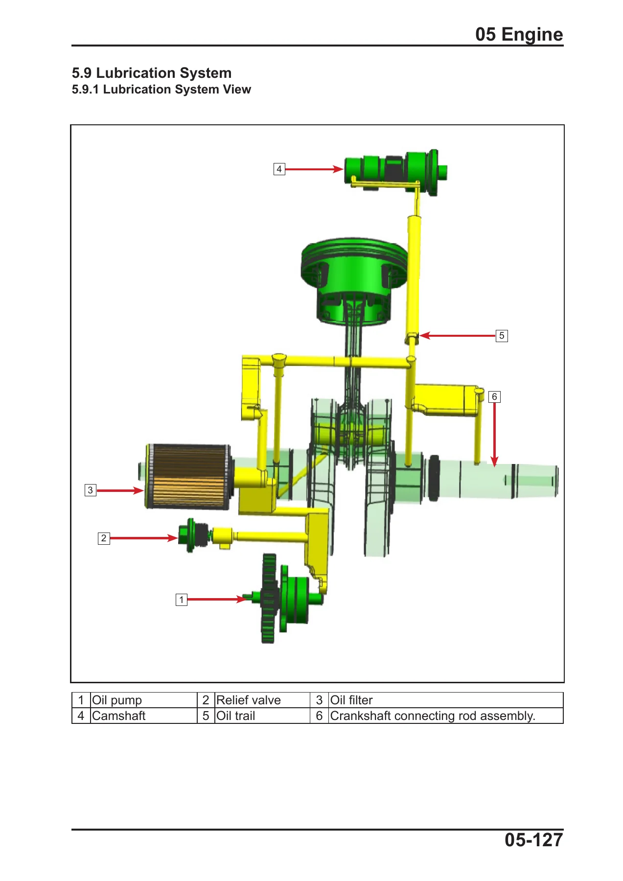
Procedures are illustrated throughout with exploded views, cutaway drawings and step-by-step removal images that show which bolt comes out and in what order. The lubrication system view and cooling system view explain the oil and coolant routing clearly. The electrical chapter is supported by EFI structure diagrams, sensor circuit diagrams showing how each component connects back to the ECU, connector pinout views for the TPS, T-MAP, water temperature sensor, oxygen sensor, trigger, speed sensor and gear position sensor, and a relay and fuse box layout with the relay positions labelled. Two wiring appendices – Appendix A for the EFI diagram and Appendix B for the electrical schematic diagram – cover the complete vehicle harness, and there are dedicated fault code tables for MSE 6.0, MSE 8.0, T-BOX and DASH so a stored code can be traced to its cause instead of swapped parts.

Get The Complete 2024 CFMOTO CFORCE Service Manual

With this full workshop repair PDF on hand, a CFORCE 400, 450, 500 or 520 can be serviced from routine oil, filter, coolant and gear case oil changes through to engine teardown, CVT overhaul, gear case rebuild, brake and suspension repair, and electrical or EFI fault finding. Having the correct torque values, service limits, adjustment procedures and wiring references is what separates a repair that lasts from one that comes back – and it is the reason a factory-level service manual is the first tool any serious owner or independent workshop buys for these machines.

IMAGES PREVIEW

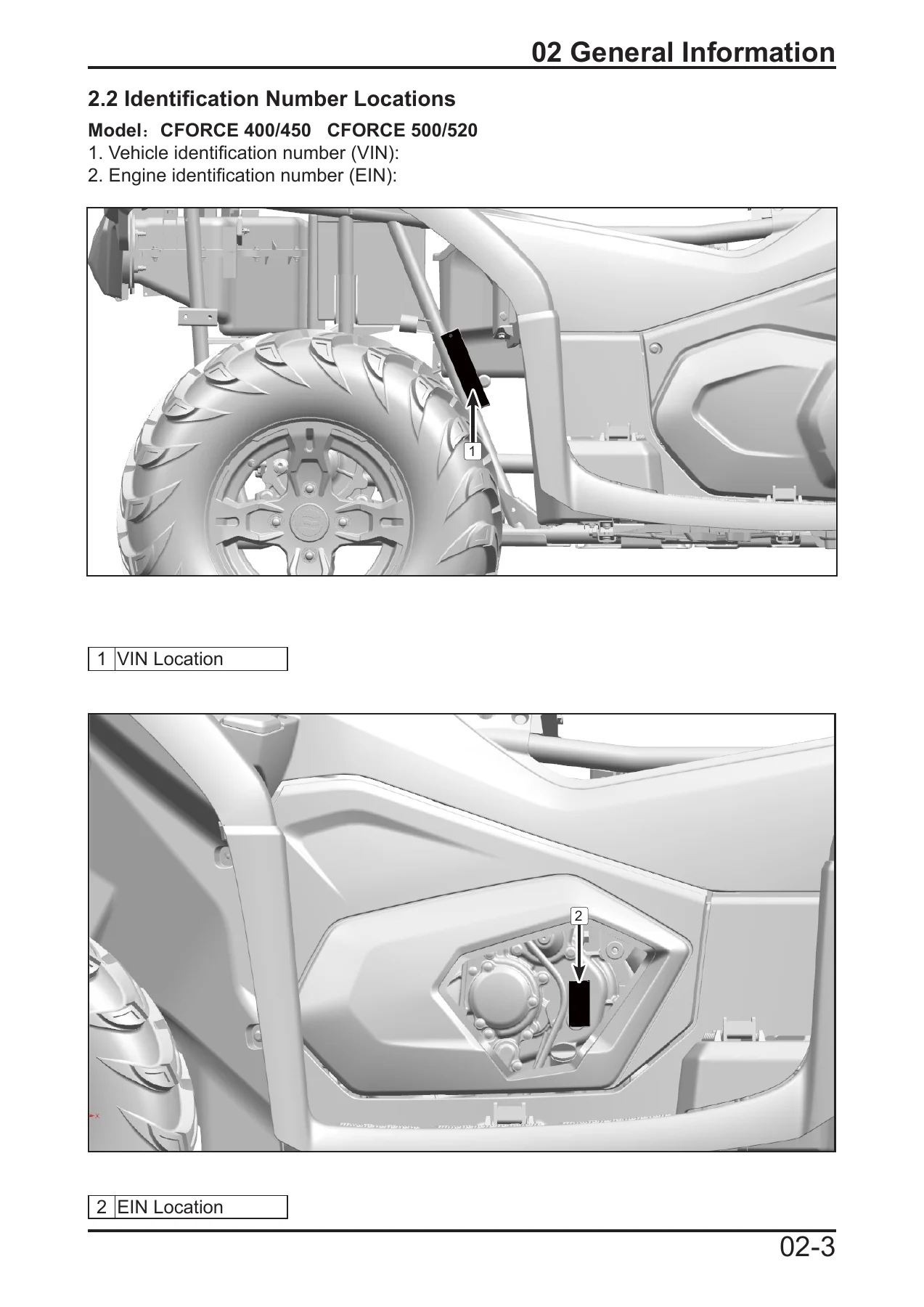
2024 CFMOTO CFORCE 400 450 500 520 Service Manual - Full Workshop Repair PDF β€” PDF page 12 preview
2024 CFMOTO CFORCE 400 450 500 520 Service Manual - Full Workshop Repair PDF β€” PDF page 177 preview
2024 CFMOTO CFORCE 400 450 500 520 Service Manual - Full Workshop Repair PDF β€” PDF page 40 preview

Delivery is instant. The file downloads immediately after payment as a PDF that opens on a laptop, tablet or phone, needs no special software, and can be printed page by page for the workshop bench or kept on a device in the garage. No shipping, no waiting, no separate parts to order – just the complete 358-page 2024 CFMOTO CFORCE 400 450 500 520 Service Manual ready to use.

Reviews

There are no reviews yet.

Be the first to review “2024 CFMOTO CFORCE 400 450 500 520 Service Manual – Full Workshop Repair PDF”

What Our Customers Say

β˜…β˜…β˜…β˜…β˜… Live reviews from customers
Loading customer reviews...
0
    0
    Your Cart
    Your cart is emptyReturn to Shop
    πŸ›’
    Recently Purchased
    πŸ•’ verified order