
Airbus A318 A319 A320 A321 Chapter 31 Indicating and Recording Systems Maintenance Manual AES Rev 40 2012
$44.95 Original price was: $44.95.$24.95Current price is: $24.95.
Comprehensive Airbus A318, A319, A320 and A321 Aircraft Maintenance Manual Chapter 31 covering indicating and recording systems. This AES Revision 40 manual includes CFDS/CFDIU, digital flight-data recording, AIDS, ECAM and central warning systems, EIS, PFD and ND displays, display management, system pages, component removal/installation, servicing, operational tests, BITE functions and detailed system diagrams.
Description
Airbus A318 / A319 / A320 / A321 Chapter 31 Indicating and Recording Systems Maintenance Manual – AES Rev 40 (2012)
The Airbus A318 A319 A320 A321 Chapter 31 Indicating and Recording Systems Maintenance Manual AES Rev 40 2012 is a detailed aircraft maintenance reference devoted to ATA Chapter 31 systems across the A318, A319, A320 and A321 family. At 2061 PDF pages, it brings together system descriptions, component architecture, maintenance practices, servicing instructions, removal and installation tasks, operational tests, BITE procedures and extensive technical illustrations for the aircraft’s indicating, warning, display, fault-reporting and data-recording equipment.
Coverage extends from the electrical clock and cockpit indicating panels through the Centralized Fault Display System, digital flight-data recording, Aircraft Integrated Data System functions, ECAM warning and system displays, the Electronic Instrument System, Primary Flight Display, Navigation Display and associated display-management equipment. The document also contains numerous aircraft-configuration applicability statements, making it important to follow the applicability shown with each individual task or figure.
Chapter 31 Maintenance and Diagnostic Scope
This Airbus Chapter 31 manual combines descriptive material with practical maintenance procedures. System architecture sections explain how computers, display units, acquisition concentrators, recorders, data interfaces and cockpit controls communicate. Maintenance sections then provide the task structure needed for component access, removal, installation, servicing, testing and system checks.
Centralized maintenance functions receive especially extensive treatment. The CFDS and CFDIU material covers architecture, system BITE communication, fault storage, maintenance phases, report generation, MCDU menu access, post-flight reporting, avionics status, ground scanning, system report/test functions, back-up mode operation and maintenance-filter handling. Procedures are included for reading Class 3 faults, accessing individual SYSTEM REPORT/TEST pages and carrying out CFDIU operational or BITE tests.
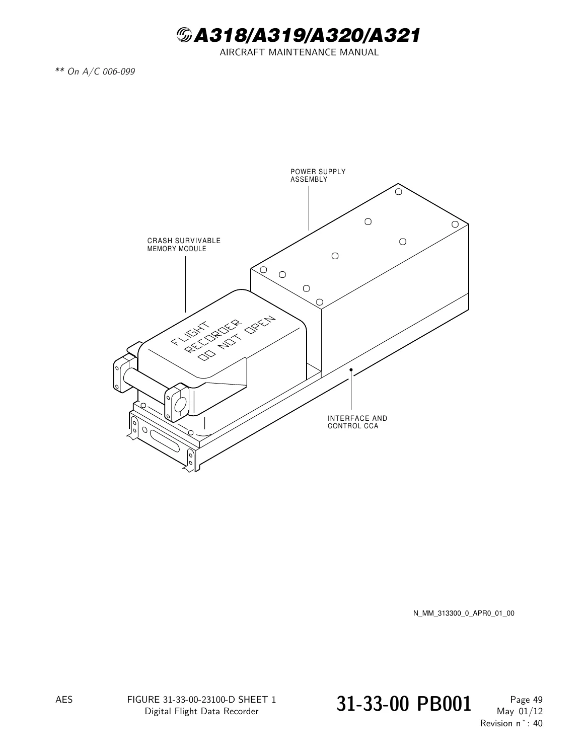
The recording-system material follows the Digital Flight Data Recording System through its interconnections, Flight Data Interface Unit or Flight Data Interface and Management Unit arrangements, Digital Flight Data Recorder, accelerometer and related interfaces. The manual includes DFDR readout procedures, coding-plug information, operational checks, recorder and accelerometer tests, and component removal and installation procedures. Detailed figures show recorders, system block diagrams, interconnection schematics and data-source relationships.
Flight Warning, ECAM and Electronic Instrument Systems
A large portion of the Airbus A318 A319 A320 A321 Chapter 31 Indicating and Recording Systems Maintenance Manual AES Rev 40 2012 is dedicated to the aircraft’s warning and electronic display architecture. Central Warning Systems coverage includes the Flight Warning Computers, System Data Acquisition Concentrators, ECAM control panel, warning and caution interfaces, ECAM display behavior, power supply relationships and system fault presentation.
Adjustment and test tasks address Flight Warning Computer operation, SDAC operation, ECAM control-panel testing, circuit-breaker monitoring and programming-data functions. Separate removal and installation sections cover equipment such as the Flight Warning Computer, SDAC, ECAM control panel and loudspeakers.
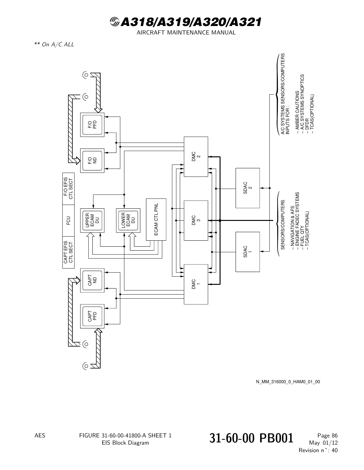
The Electronic Instrument System material develops the relationship between Display Management Computers, display units, EFIS controls, ECAM controls, PFDs and Navigation Displays. It includes system start and stop procedures, EIS operational testing, EFIS/ECAM switching tests, display-unit brightness functions, input tests and overall system testing. Wiring and interface illustrations show the relationships between display units, brightness controls, DMCs and transfer-selector functions.
Display and Recording References
Primary Flight Display and Navigation Display chapters contain extensive illustrated presentation material. PFD subjects include flight-director presentation, flight-path information, attitude-related displays and display parameters. Navigation Display coverage includes multiple operating presentations and navigation symbology together with TCAS indications, terrain display information and other display modes represented in the manual.
ECAM coverage extends beyond the warning display to system/status pages for aircraft functions including air conditioning and cabin pressure, electrical, flight controls, fuel, hydraulic, wheels, oxygen, bleed, APU, doors/oxygen and engine displays. These sections document the presentation and acquisition/interface relationships used to produce the information shown to the crew.
Complete Bookmarks
The complete bookmarks in the “Airbus A318 A319 A320 A321 Chapter 31 Indicating and Recording Systems Maintenance Manual AES Rev 40 2012” are as follows:
+Chapter 31 – INDICATING/RECORDING SYSTEMSp. 1
+31-00 – INDICATING/RECORDING SYSTEMS – GENERALp. 27
+31-00-00 – INDICATING/RECORDING SYSTEMS – GENERALp. 27
+31-00-00 PB 001 CONF 00 – INDICATING/RECORDING SYSTEMS – GENERAL – DESCRIPTION AND OPERATIONp. 27
+31-10 – INSTRUMENTS AND CONTROL PANELSp. 42
+31-10-00 – INSTRUMENTS AND CONTROL PANELSp. 42
+31-10-00 PB 201 CONF 00 – INSTRUMENTS AND CONTROL PANELS – MAINTENANCE PRACTICESp. 42
+31-14 – OVERHEAD PANELp. 57
+31-14-25 – OVERHEAD CONTROL AND INDICATING PANELp. 57
+31-14-25 PB 201 CONF 00 – OVERHEAD CONTROL AND INDICATING PANEL – MAINTENANCE PRACTICESp. 57
+31-14-25-860-002-A – Floor Path Emergency-Lighting Inhibition With Removal of the Overhead Panel 25VUp. 57
+31-21 – ELECTRICAL CLOCKp. 61
+31-21-00 – ELECTRICAL CLOCKp. 61
+31-21-00 PB 001 CONF 00 – ELECTRICAL CLOCK – DESCRIPTION AND OPERATIONp. 61
+31-21-00 PB 501 CONF 00 – ELECTRICAL CLOCK – ADJUSTMENT/TESTp. 74
+31-21-00-750-002-A – Procedure to set the Clockp. 74
+31-21-21 – CLOCKp. 80
+31-21-21 PB 401 CONF 00 – CLOCK – REMOVAL/INSTALLATIONp. 80
+31-21-21-000-001-A – Removal of the Clockp. 80
+31-30 – CENTRALIZED FAULT DISPLAY SYSTEM (CFDS) AND DATA RECORDING SYSTEMp. 87
+31-30-00 – CENTRALIZED FAULT DISPLAY SYSTEM (CFDS) AND DATA RECORDING SYSTEMp. 87
+31-30-00 PB 001 CONF 00 – CENTRALIZED FAULT DISPLAY SYSTEM (CFDS) AND DATA RECORDING SYSTEM – DESCRIPTION AND OPERATIONp. 87
+31-32 – CENTRALIZED FAULT DISPLAY INTERFACE (CFDIU)p. 93
+31-32-00 – CENTRALIZED FAULT DISPLAY INTERFACE (CFDIU)p. 93
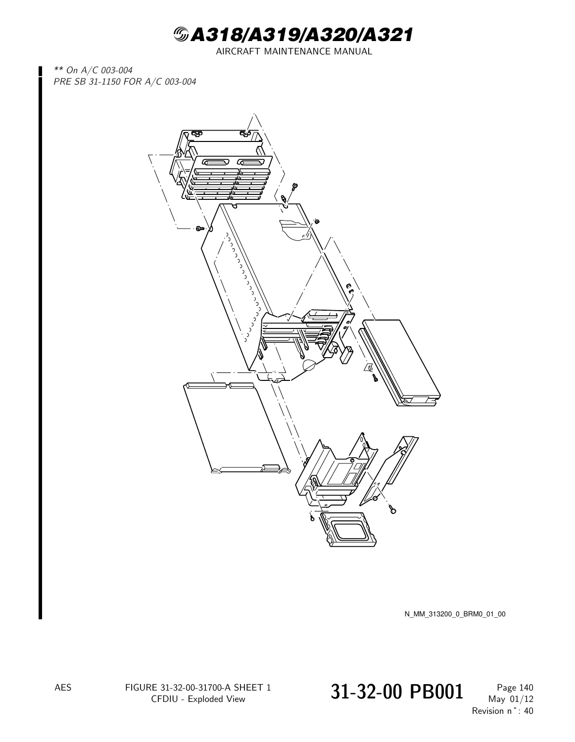
+31-32-00 PB 001 CONF 00 – CENTRALIZED FAULT DISPLAY INTERFACE (CFDIU) – DESCRIPTION AND OPERATIONp. 93
+31-32-00 PB 201 CONF 00 – CENTRALIZED FAULT DISPLAY INTERFACE (CFDIU) – MAINTENANCE PRACTICESp. 282
+31-32-00-860-001-A – Procedure to Get Access to the SYSTEM REPORT/TEST Menu Pagep. 290
+31-32-00-860-002-A – Procedure to Get Access to the SYSTEM REPORT/TEST/AIR COND Pagep. 293
+31-32-00-860-003-A – Procedure to Get Access to the SYSTEM REPORT/TEST/COM Pagep. 296
+31-32-00-860-004-A – Procedure to Get Access to the SYSTEM REPORT/TEST/ELEC Pagep. 300
+31-32-00-860-005-A – Procedure to Get Access to the SYSTEM REPORT/TEST FIRE PROT Pagep. 303
+31-32-00-860-006-A – Procedure to Get Access to the SYSTEM REPORT/TEST F/CTL Pagep. 306
+31-32-00-860-007-A – Procedure to Get Access to the SYSTEM REPORT/TEST/ICE & RAIN Pagep. 309
+31-32-00-860-008-A – Procedure to Get Access to the SYSTEM REPORT/TEST/INST Pagep. 312
+31-32-00-860-009-A – Procedure to Get Access to the SYSTEM REPORT/TEST/L/G Pagep. 315
+31-32-00-860-010-A – Procedure to Get Access to the SYSTEM REPORT/TEST NAV Pagep. 318
+31-32-00-860-011-A – Procedure to Get Access to the SYSTEM REPORT/TEST/PNEU Pagep. 322
+31-32-00-860-012-A – Procedure to Get Access to the SYSTEM REPORT/TEST/ENG Pagep. 325
+31-32-00-860-013-A – Procedure to Get Access to the SYSTEM REPORT/TEST/INFO SYS Pagep. 328
+31-32-00-860-014-A – Procedure to Get Access to the SYSTEM REPORT/TEST/FUEL Pagep. 331
+31-32-00 PB 301 CONF 00 – CENTRALIZED FAULT DISPLAY INTERFACE (CFDIU) – SERVICINGp. 334
+31-32-00 PB 501 CONF 00 – CENTRALIZED FAULT DISPLAY INTERFACE (CFDIU) – ADJUSTMENT/TESTp. 346
+31-32-34 – INTERFACE UNIT – CENTRALIZED FAULT DISPLAY (CFDIU)p. 357
+31-32-34 PB 401 CONF 00 – INTERFACE UNIT – CENTRALIZED FAULT DISPLAY (CFDIU) – REMOVAL/INSTALLATIONp. 357
+31-32-34-000-001-A – Removal of the CFDIUp. 357
+31-33 – DIGITAL FLIGHT DATA RECORDING SYSTEM INTERCONNECTIONp. 363
+31-33-00 – DIGITAL FLIGHT DATA RECORDING SYSTEM INTERCONNECTIONp. 363
+31-33-00 PB 001 CONF 00 – DIGITAL FLIGHT DATA RECORDING SYSTEM INTERCONNECTION – DESCRIPTION AND OPERATIONp. 363
+31-33-00 PB 201 CONF 00 – DIGITAL FLIGHT DATA RECORDING SYSTEM INTERCONNECTION – MAINTENANCE PRACTICESp. 424
+31-33-00-710-009-A – Readout Procedure of the Digital Flight Data Recorderp. 425
+31-33-00-710-010-A – Procedure to Use the Aircraft Coding Plug 197VC-Ap. 429
+31-33-00 PB 501 CONF 00 – DIGITAL FLIGHT DATA RECORDING SYSTEM INTERCONNECTION – ADJUSTMENT/TESTp. 434
+31-33-00-710-001-A – Operational Test of the Power Interlocks and Status Monitoringp. 434
+31-33-00-710-006-A – Operational Check of DFDR through the MCDUp. 441
+31-33-16 – ACCELEROMETER – THREE AXISp. 461
+31-33-16 PB 401 CONF 00 – ACCELEROMETER – THREE AXIS – REMOVAL/INSTALLATIONp. 461
+31-33-16-000-001-A – Removal of the Three-Axis-Accelerometer (LA)p. 461
+31-33-34 – INTERFACE UNIT – FLIGHT DATA (FDIU)p. 466
+31-33-34 PB 401 CONF 00 – INTERFACE UNIT – FLIGHT DATA (FDIU) – REMOVAL/INSTALLATIONp. 466
+31-33-34-000-001-A – Removal of the Flight Data Interface Unit (FDIU)p. 466
+31-33-55 – RECORDER – DIGITAL FLIGHT DATA (DFDR)p. 471
+31-33-55 PB 401 CONF 00 – RECORDER – DIGITAL FLIGHT DATA (DFDR) – REMOVAL/INSTALLATIONp. 471
+31-33-55-000-001-A – Removal of the Digital Flight Data Recorder (DFDR)p. 471
+31-33-55-920-001-A – Discard Underwater Locator Beacon Batteryp. 476
+31-35 – MULTIFUNCTION PRINTINGp. 480
+31-35-00 – MULTIFUNCTION PRINTINGp. 480
+31-35-00 PB 001 CONF 00 – MULTIFUNCTION PRINTING – DESCRIPTION AND OPERATIONp. 480
+31-35-00 PB 501 CONF 00 – MULTIFUNCTION PRINTING – ADJUSTMENT/TESTp. 492
+31-35-22 – PRINTERp. 494
+31-35-22 PB 301 CONF 00 – PRINTER – SERVICINGp. 494
+31-35-22-600-001-A – Servicing of the Printerp. 494
+31-35-22 PB 401 CONF 00 – PRINTER – REMOVAL/INSTALLATIONp. 497
+31-35-22-000-001-A – Removal of the Printerp. 497
+31-36 – AIDS INTERCONNECTIONp. 502
+31-36-00 – AIDS INTERCONNECTIONp. 502
+31-36-00 PB 001 CONF 01 – AIDS INTERCONNECTION (DMU, DAR) – DESCRIPTION AND OPERATIONp. 502
+31-36-00 PB 201 CONF 00 – AIDS INTERCONNECTION – MAINTENANCE PRACTICESp. 702
+31-36-00-740-010-A – Printout of Stored Reportsp. 726
+31-36-00-740-011-A – Printout of Manually Requested Reportsp. 730
+31-36-00-000-001-A – Removal of the Personal Computer Memory Card (PCMCIA) of the FDIMU/DMUp. 757
+31-36-00-960-003-A – Replacement of the FDIMU Batteriesp. 764
+31-36-00-960-002-A – Replacement of the DMU Batteriesp. 767
+31-36-00 PB 501 CONF 00 – AIDS INTERCONNECTION – ADJUSTMENT/TESTp. 770
+31-36-34 – MANAGEMENT UNIT – DATA (DMU OR FDIMU)p. 776
+31-36-34 PB 401 CONF 00 – MANAGEMENT UNIT – DATA (DMU OR FDIMU) – REMOVAL/INSTALLATIONp. 776
+31-36-34-000-001-A – Removal of the Data Management Unit (DMU)p. 776
+31-36-34-000-002-A – Removal of the FDIU/DMU (FDIMU)p. 779
+31-37 – AIDS INPUT INTERFACEp. 788
+31-37-00 – AIDS INPUT INTERFACEp. 788
+31-37-00 PB 001 CONF 00 – AIDS INPUT INTERFACE – DESCRIPTION AND OPERATIONp. 788
+31-37-00 PB 201 CONF 00 – AIDS INPUT INTERFACE – MAINTENANCE PRACTICESp. 814
+31-37-00-200-001-A – Check of the Load-Report Parameter after Hard/Overweight Landing or Excessive Turbulencep. 814
+31-37-21 – AIDS – ECS REPORTSp. 823
+31-37-21 PB 001 CONF 00 – AIDS – ECS REPORTS – DESCRIPTION AND OPERATIONp. 823
+31-37-49 – AIDS – APU REPORTSp. 844
+31-37-49 PB 001 CONF 00 – AIDS – APU REPORTS – DESCRIPTION AND OPERATIONp. 844
+31-37-51 – AIDS – STRUCTURE REPORTSp. 868
+31-37-51 PB 001 CONF 00 – AIDS – STRUCTURE REPORTS – DESCRIPTION AND OPERATIONp. 868
+31-37-73 – AIDS – ENGINE REPORTSp. 897
+31-37-73 PB 001 CONF 01 – AIDS – ENGINE REPORTS – DESCRIPTION AND OPERATIONp. 897
+31-38 – UP AND DOWN DATA LOADING SYSTEM ACQUISITION/INTERFACE AND EQUIPMENTp. 1056
+31-38-00 – UP AND DOWN DATA LOADING SYSTEM ACQUISITION/INTERFACE AND EQUIPMENTp. 1056
+31-38-00 PB 001 CONF 00 – UP AND DOWN DATA LOADING SYSTEM ACQUISITION/INTERFACE AND EQUIPMENT – DESCRIPTION AND OPERATIONp. 1056
+31-50 – CENTRAL WARNING SYSTEMSp. 1058
+31-50-00 – CENTRAL WARNING SYSTEMSp. 1058
+31-50-00 PB 001 CONF 00 – CENTRAL WARNING SYSTEMS – DESCRIPTION AND OPERATIONp. 1058
+31-50-00 PB 501 CONF 00 – CENTRAL WARNING SYSTEMS – ADJUSTMENT/TESTp. 1147
+31-50-00-740-002-A – Read and Decode the Hardware Pin Programming of the SDAC and FWCp. 1162
+31-50-00-740-003-A – Read FWC Software Pin Programmingp. 1195
+31-51 – OPERATIONAL PRESENTATIONp. 1210
+31-51-00 – OPERATIONAL PRESENTATIONp. 1210
+31-51-00 PB 001 CONF 00 – OPERATIONAL PRESENTATION – DESCRIPTION AND OPERATIONp. 1210
+31-51-00 PB 301 CONF 00 – OPERATIONAL PRESENTATION – SERVICINGp. 1218
+31-52 – FWC – ACQUISITION/INTERFACEp. 1239
+31-52-00 – FWC – ACQUISITION/INTERFACEp. 1239
+31-52-00 PB 001 CONF 01 – FWC – ACQUISITION/INTERFACE – DESCRIPTION AND OPERATIONp. 1239
+31-53 – FLIGHT WARNING COMPUTER (FWC)p. 1243
+31-53-21 – LOUD SPEAKERp. 1243
+31-53-21 PB 401 CONF 00 – LOUD SPEAKER – REMOVAL/INSTALLATIONp. 1243
+31-53-21-000-001-A – Removal of the Loudspeakersp. 1243
+31-53-34 – COMPUTER – FLIGHT WARNING (FWC)p. 1248
+31-53-34 PB 401 CONF 00 – COMPUTER – FLIGHT WARNING (FWC) – REMOVAL/INSTALLATIONp. 1248
+31-53-34-000-001-A – Removal of the Flight Warning Computer (FWC)p. 1248
+31-54 – SDAC – ACQUISITION/INTERFACEp. 1255
+31-54-00 – SDAC – ACQUISITION/INTERFACEp. 1255
+31-54-00 PB 001 CONF 01 – SDAC – ACQUISITION/INTERFACE – DESCRIPTION AND OPERATIONp. 1255
+31-55 – SYSTEM DATA ACQUISITION CONCENTRATOR (SDAC)p. 1260
+31-55-34 – CONCENTRATOR – SYSTEM DATA ACQUISITION (SDAC)p. 1260
+31-55-34 PB 401 CONF 00 – CONCENTRATOR – SYSTEM DATA ACQUISITION (SDAC) – REMOVAL/INSTALLATIONp. 1260
+31-55-34-000-001-A – Removal of the SDACp. 1260
+31-56 – ECAM CONTROL PANELp. 1266
+31-56-00 – ECAM CONTROL PANELp. 1266
+31-56-00 PB 001 CONF 00 – ECAM CONTROL PANEL – DESCRIPTION AND OPERATIONp. 1266
+31-60 – ELECTRONIC INSTRUMENT SYSTEM (EIS)p. 1279
+31-60-00 – ELECTRONIC INSTRUMENT SYSTEM (EIS)p. 1279
+31-60-00 PB 001 CONF 00 – ELECTRONIC INSTRUMENT SYSTEM (EIS) – DESCRIPTION AND OPERATIONp. 1279
+31-60-00 PB 201 CONF 00 – ELECTRONIC INSTRUMENT SYSTEM (EIS) – MAINTENANCE PRACTICESp. 1367
+31-60-00 PB 501 CONF 00 – ELECTRONIC INSTRUMENT SYSTEM (EIS) – ADJUSTMENT/TESTp. 1371
+31-61 – EIS – CONTROLp. 1389
+31-61-00 – EIS – CONTROLp. 1389
+31-61-00 PB 001 CONF 00 – EIS – CONTROL – DESCRIPTION AND OPERATIONp. 1389
+31-61-12 – CONTROL PANEL – ECAMp. 1408
+31-61-12 PB 401 CONF 00 – CONTROL PANEL – ECAM – REMOVAL/INSTALLATIONp. 1408
+31-61-12-000-001-A – Removal of the ECAM Control Panelp. 1408
+31-62 – DMC – ACQUISITION/INTERFACEp. 1412
+31-62-00 – DMC – ACQUISITION/INTERFACEp. 1412
+31-62-00 PB 001 CONF 00 – DMC – ACQUISITION/INTERFACE – DESCRIPTION AND OPERATIONp. 1412
+31-63 – DISPLAY MANAGEMENT COMPUTER (DMC)p. 1469
+31-63-00 – DISPLAY MANAGEMENT COMPUTER (DMC)p. 1469
+31-63-00 PB 001 CONF 00 – DISPLAY MANAGEMENT COMPUTER (DMC) – DESCRIPTION AND OPERATIONp. 1469
+31-63-00 PB 401 CONF 00 – DISPLAY MANAGEMENT COMPUTER (DMC) – DEACTIVATION/REACTIVATIONp. 1520
+31-63-22 – DISPLAY UNITp. 1524
+31-63-22 PB 401 CONF 00 – DISPLAY UNIT – REMOVAL/INSTALLATIONp. 1524
+31-63-22-000-001-A – Removal of the Display Unitp. 1524
+31-63-22 PB 601 CONF 00 – DISPLAY UNIT – INSPECTION/CHECKp. 1537
+31-63-22-200-001-A – Measurement of the Display Unit Brightnessp. 1537
+31-63-22 PB 701 CONF 00 – DISPLAY UNIT – CLEANING/PAINTINGp. 1543
+31-63-34 – COMPUTER – DISPLAY MANAGEMENT (DMC)p. 1545
+31-63-34 PB 401 CONF 00 – COMPUTER – DISPLAY MANAGEMENT (DMC) – REMOVAL/INSTALLATIONp. 1545
+31-63-34-000-001-A – Removal of the DMCp. 1545
+31-64 – PRIMARY FLIGHT DISPLAY (PFD)p. 1550
+31-64-00 – PRIMARY FLIGHT DISPLAY (PFD)p. 1550
+31-64-00 PB 001 CONF 00 – PRIMARY FLIGHT DISPLAY (PFD) – DESCRIPTION AND OPERATIONp. 1550
+31-65 – NAVIGATION DISPLAY (ND)p. 1663
+31-65-00 – NAVIGATION DISPLAY (ND)p. 1663
+31-65-00 PB 001 CONF 00 – NAVIGATION DISPLAY (ND) – DESCRIPTION AND OPERATIONp. 1663
+31-66 – ECAM ENGINE/WARNING DISPLAYp. 1762
+31-66-00 – ECAM ENGINE/WARNING DISPLAYp. 1762
+31-66-00 PB 001 CONF 13 – ECAM ENGINE/WARNING DISPLAY – DESCRIPTION AND OPERATIONp. 1762
+31-67 – ECAM SYSTEM/STATUS DISPLAYp. 1805
+31-67-00 – ECAM SYSTEM/STATUS DISPLAYp. 1805
+31-67-00 PB 001 CONF 00 – ECAM SYSTEM/STATUS DISPLAY – DESCRIPTION AND OPERATIONp. 1805
+31-67-21 – SYSTEM DISPLAY – COND & CAB PRESS PAGESp. 1837
+31-67-21 PB 001 CONF 00 – SYSTEM DISPLAY – COND & CAB PRESS PAGES – DESCRIPTION AND OPERATIONp. 1837
+31-67-24 – SYSTEM DISPLAY – ELEC PAGEp. 1860
+31-67-24 PB 001 CONF 00 – SYSTEM DISPLAY – ELEC PAGE – DESCRIPTION AND OPERATIONp. 1860
+31-67-27 – SYSTEM DISPLAY – F/CTL PAGEp. 1875
+31-67-27 PB 001 CONF 00 – SYSTEM DISPLAY – F/CTL PAGE – DESCRIPTION AND OPERATIONp. 1875
+31-67-28 – SYSTEM DISPLAY – FUEL PAGEp. 1882
+31-67-28 PB 001 CONF 00 – SYSTEM DISPLAY – FUEL PAGE – DESCRIPTION AND OPERATIONp. 1882
+31-67-29 – SYSTEM DISPLAY – HYD PAGEp. 1901
+31-67-29 PB 001 CONF 00 – SYSTEM DISPLAY – HYD PAGE – DESCRIPTION AND OPERATIONp. 1901
+31-67-32 – SYSTEM DISPLAY – WHEEL PAGEp. 1915
+31-67-32 PB 001 CONF 00 – SYSTEM DISPLAY – WHEEL PAGE – DESCRIPTION AND OPERATIONp. 1915
+31-67-35 – SYSTEM DISPLAY – OXY PAGEp. 1926
+31-67-35 PB 001 CONF 00 – SYSTEM DISPLAY – OXY PAGE – DESCRIPTION AND OPERATIONp. 1926
+31-67-36 – SYSTEM DISPLAY – BLEED PAGEp. 1927
+31-67-36 PB 001 CONF 00 – SYSTEM DISPLAY – BLEED PAGE – DESCRIPTION AND OPERATIONp. 1927
+31-67-49 – SYSTEM DISPLAY – APU PAGEp. 1943
+31-67-49 PB 001 CONF 00 – SYSTEM DISPLAY – APU PAGE – DESCRIPTION AND OPERATIONp. 1943
+31-67-52 – SYSTEM DISPLAY – DOOR/OXY PAGEp. 1953
+31-67-52 PB 001 CONF 00 – SYSTEM DISPLAY – DOOR/OXY PAGE – DESCRIPTION AND OPERATIONp. 1953
+31-67-77 – SYSTEM DISPLAY – ENGINE PAGEp. 1964
+31-67-77 PB 001 CONF 00 – SYSTEM DISPLAY – ENGINE PAGE – DESCRIPTION AND OPERATIONp. 1964
+31-68 – EIS – SWITCHINGp. 1973
+31-68-00 – EIS – SWITCHINGp. 1973
+31-68-00 PB 001 CONF 00 – EIS – SWITCHING – DESCRIPTION AND OPERATIONp. 1973
+31-68-00 PB 401 CONF 00 – EIS – SWITCHING – DEACTIVATION/REACTIVATIONp. 2004
+31-69 – EIS – TEST/BITEp. 2024
+31-69-00 – EIS – TEST/BITEp. 2024
+31-69-00 PB 001 CONF 00 – EIS – TEST/BITE – DESCRIPTION AND OPERATIONp. 2024
The Aircraft Integrated Data System sections cover DMU and FDIMU configurations, data interfaces, report generation, parameter call-up, programming, stored and manually requested reports, software and database loading, PCMCIA-card procedures, data downloading and unit battery replacement. The manual also includes AIDS input-interface material and report sections for ECS, APU, structural load and engine-related data.
File Details
- Manual type: Aircraft Maintenance Manual – Chapter 31
- Aircraft: A318 / A319 / A320 / A321
- Chapter: 31 – Indicating/Recording Systems
- Revision: 40
- Date: May 01/12
- Language: English
- Page count: 2061 pages
- File format: PDF
Chapters Covered
- 31-00-00 – Indicating/Recording Systems – General
- 31-10-00 – Instruments and Control Panels – Maintenance Practices
- 31-14-25 – Overhead Control and Indicating Panel
- 31-21-00 – Electrical Clock
- 31-21-21 – Clock Removal/Installation
- 31-30-00 – Centralized Fault Display System and Data Recording System
- 31-32-00 – Centralized Fault Display Interface (CFDIU)
- 31-32-34 – Centralized Fault Display Interface Unit Removal/Installation
- 31-33-00 – Digital Flight Data Recording System Interconnection
- 31-33-16 – Three-Axis Accelerometer
- 31-33-34 – Flight Data Interface Unit
- 31-33-55 – Digital Flight Data Recorder
- 31-35-00 – Multifunction Printing
- 31-35-22 – Printer
- 31-36-00 – AIDS Interconnection
- 31-36-34 – Data Management Unit / FDIMU
- 31-37-00 – AIDS Input Interface
- 31-37-21 – AIDS ECS Reports
- 31-37-49 – AIDS APU Reports
- 31-37-51 – AIDS Structure Reports
- 31-37-73 – AIDS Engine Reports
- 31-38-00 – Up and Down Data Loading System Acquisition/Interface and Equipment
- 31-50-00 – Central Warning Systems
- 31-51-00 – Operational Presentation
- 31-52-00 – FWC Acquisition/Interface
- 31-53-21 – Loudspeaker Removal/Installation
- 31-53-34 – Flight Warning Computer Removal/Installation
- 31-54-00 – SDAC Acquisition/Interface
- 31-55-34 – System Data Acquisition Concentrator Removal/Installation
- 31-56-00 – ECAM Control Panel
- 31-60-00 – Electronic Instrument System
- 31-61-00 – EIS Control
- 31-61-12 – ECAM Control Panel Removal/Installation
- 31-62-00 – DMC Acquisition/Interface
- 31-63-00 – Display Management Computer
- 31-63-22 – Display Unit
- 31-63-34 – Display Management Computer Removal/Installation
- 31-64-00 – Primary Flight Display
- 31-65-00 – Navigation Display
- 31-66-00 – ECAM Engine/Warning Display
- 31-67-00 – ECAM System/Status Display
- 31-67-21 – COND and CAB PRESS Pages
- 31-67-24 – ELEC Page
- 31-67-27 – F/CTL Page
- 31-67-28 – FUEL Page
- 31-67-29 – HYD Page
- 31-67-32 – WHEEL Page
- 31-67-35 – OXY Page
- 31-67-36 – BLEED Page
- 31-67-49 – APU Page
- 31-67-52 – DOOR/OXY Page
- 31-67-77 – ENGINE Page
- 31-68-00 – EIS Switching
- 31-69-00 – EIS Test/BITE
IMAGES PREVIEW
Taken together, these sections provide a broad Chapter 31 maintenance reference for understanding system architecture, following aircraft-specific maintenance tasks, replacing relevant LRUs, carrying out operational tests, accessing maintenance reports and interpreting the display, recording and fault-monitoring systems used across the A318/A319/A320/A321 family.
Maintain, Test and Diagnose Chapter 31 Systems
The Airbus A318 A319 A320 A321 Chapter 31 Indicating and Recording Systems Maintenance Manual AES Rev 40 2012 supports practical work on cockpit indication, ECAM and EIS equipment, centralized fault reporting, data recording, printers, DMU/FDIMU functions, display-management computers, PFD and ND systems, Flight Warning Computers, SDACs and associated interfaces. The combination of procedures, system descriptions, component-location information, block diagrams, wiring/interface drawings and test instructions helps technicians work from the documented configuration and task requirements rather than relying on general assumptions.
Correct maintenance data matters when dealing with interconnected avionics and recording systems, where component configuration, aircraft applicability, test sequence and system interfaces can affect the job. This manual is supplied as an instant PDF download after purchase, with no physical shipping required. It can be viewed on compatible computers, tablets and phones and printed for workshop or maintenance-reference use.
What Our Customers Say
🌟 Related Products
Discover more professional manuals for your equipment
Canadair Regional Jet Chapter 34 Navigation Aircraft Maintenance Manual - December 2005
Airbus A318/A319/A320/A321 Maintenance Manual - Chapter 25 Equipment & Furnishings - AES Rev 40 (2012) PDF
A318 A319 A320 A321 Chapter 21 Air Conditioning Aircraft Maintenance Manual - KNA Rev 12
Reviews
There are no reviews yet.