
Airbus A318 A319 A320 A321 SR Technics Level III Training Manual PDF
Original price was: $39.95.$23.95Current price is: $23.95.
3730-page SR Technics A320-family technical training reference covering aircraft systems, structures, APUs and V2500A powerplant systems.
Description
Airbus A318, A319, A320, A321 SR Technics Level III Training Manual PDF
The Airbus A318 A319 A320 A321 SR Technics Level III Training Manual PDF is a substantial English-language technical training reference for the A320 aircraft family. Across 3730 pages, it brings together aircraft familiarization, system descriptions, component illustrations, functional explanations and detailed powerplant material. The section headers identify EASA Part 66 Level III training, while the pages explicitly state that the material is for training purposes only.
This is particularly useful for readers who want to move beyond a short aircraft overview and understand how the major systems are arranged and connected. Electrical supply, hydraulic power, flight controls, fuel, environmental systems and indication are treated as individual subjects, with illustrations and component descriptions that support more detailed study. The final powerplant material concentrates on V2500A systems; the aircraft-family presentation also contains comparative information that should be read with its model and configuration labels intact.
A Broad Reference With a Clear Training Purpose
The opening material establishes terminology, aircraft identification conventions and the general arrangement before the system chapters. Dimensions, areas, lifting and shoring, leveling and weighing, towing and taxiing, parking and mooring, servicing and maintenance practices provide context for understanding the rest of the collection. These subjects help connect the named components in later diagrams to their location on the aircraft and to the terminology used throughout the training pages.
The publication brings together sections bearing different dates, including material from 2009 through 2014. It should therefore be described as the supplied training compilation, rather than assigned a single invented revision date. It is not an aircraft maintenance manual or an authorization to perform a maintenance task. Its strength is the explanation of system architecture and component relationships that can support technical study alongside the applicable current aircraft documentation.
Electrical and Hydraulic Systems Explained Together With Their Components
The electrical chapter introduces engine-driven generation, APU generation, external power, transformer rectifiers, batteries and emergency generation. It identifies the three-phase 115/200 V, 400 Hz AC system and the 28 V DC system, then explains the associated supply arrangements. Generator control units, contactors, load distribution and system-report or test subjects give the reader more than a simple list of voltage ratings.
Emergency supply is linked to the blue hydraulic system and the ram air turbine, making the relationship between electrical and hydraulic chapters especially useful. The electrical introduction also distinguishes the main generator rating from the emergency generator rating and describes the static inverter. Those distinctions help a student follow which source is being discussed in a diagram, rather than assuming every source supports the same network in the same way.
The hydraulic material includes the green, blue and yellow systems, reservoirs, pumps, manifolds, filters, ground-service connections and indications. Dedicated subjects address the power transfer unit, ram air turbine, reservoir pressurization and filling, seal drains and leakage measurement. Component drawings and functional sections allow the system names to be connected to physical equipment and to the interfaces shown in the training material.
IMAGES PREVIEW
Flight Controls, Autoflight and Indication
Flight-control training covers the control surfaces and their associated actuation and monitoring equipment. The flap material, for example, identifies the power control unit, hydraulic motors, pressure-off brakes, valve blocks and position pickup units. Related monitoring is described through the slat/flap control computers. These details make the manual useful for studying how commanded movement, hydraulic drive and position information are related.
The autoflight chapters add a different layer: computers, control functions and the system relationships involved in automatic flight. The indicating and recording material supplies the display and reporting context used elsewhere in the book. Reading these chapters together supports a clearer distinction between the equipment that produces movement, the computers that command or monitor it, and the information presented to the crew or maintenance reader.
Fuel, Environmental Systems and Aircraft Services
Fuel-system subjects include feed and indication material, family-specific sections and fuel-safety training references. The A321 fuel material is separately identifiable, which matters when comparing the family rather than treating every diagram as interchangeable across all four models. A later fuel-inerting chapter is also present. Air conditioning, pneumatic supply, ice and rain protection, oxygen, water and waste, fire protection and equipment or furnishings broaden the coverage beyond the main flight and power systems.
Communication, navigation, lights and aircraft information-management material provide additional system context. These chapters make the file suitable for a broad course of familiarization as well as for returning to an individual topic. Because the collection is organized by technical subject, a reader can approach a component from its own chapter and then consult the associated power, control or indication chapter when an interface needs explanation.
APU, Structures and V2500A Powerplant Depth
The APU material includes the APIC APS3200 and comparison subjects involving other APU installations. The structures section addresses doors, fuselage, nacelles, stabilizers, windows and wings, and includes structural-repair-manual context. Door arrangements and aircraft structure are therefore represented alongside the system-focused chapters rather than left out of an otherwise detailed family reference.
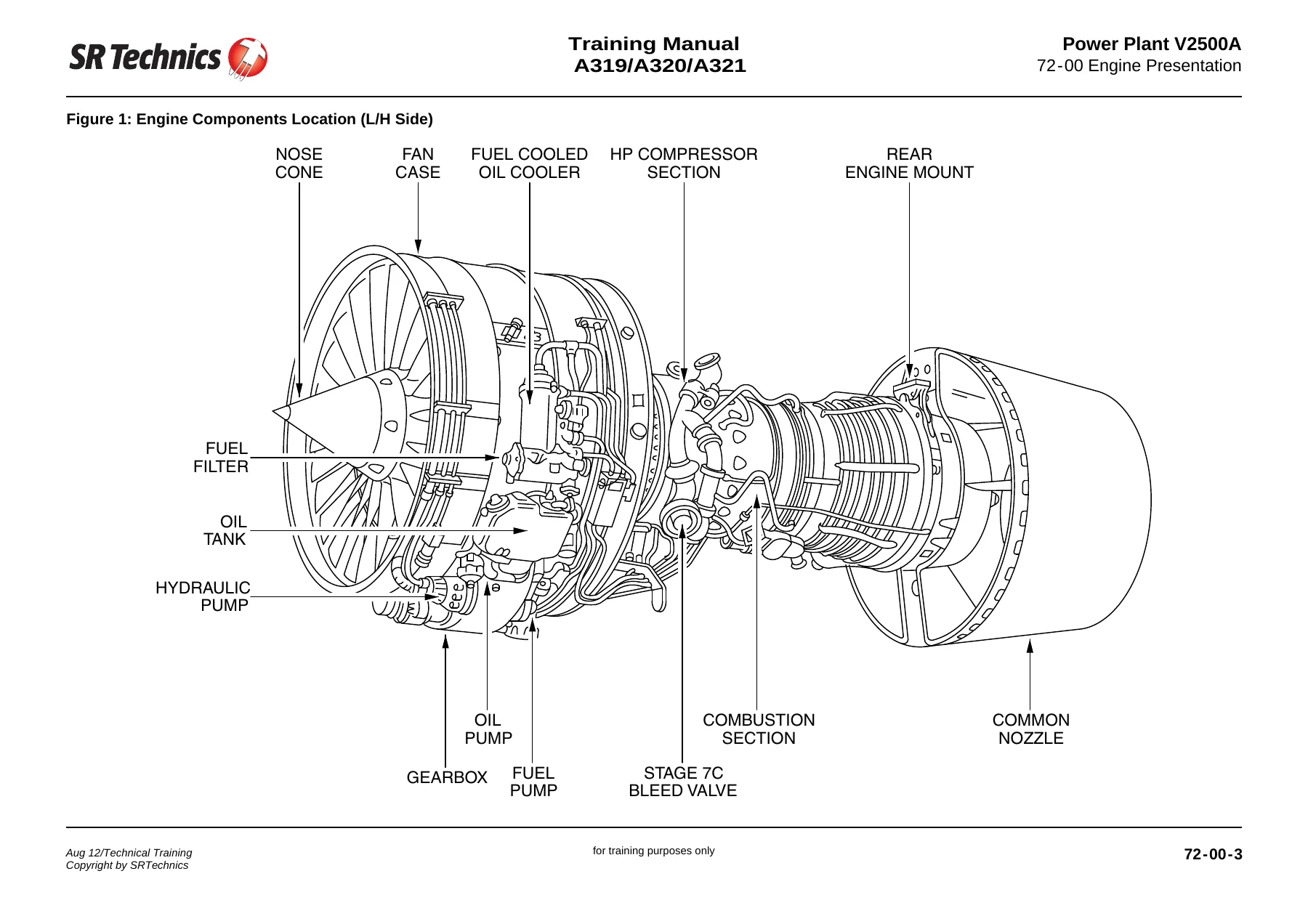
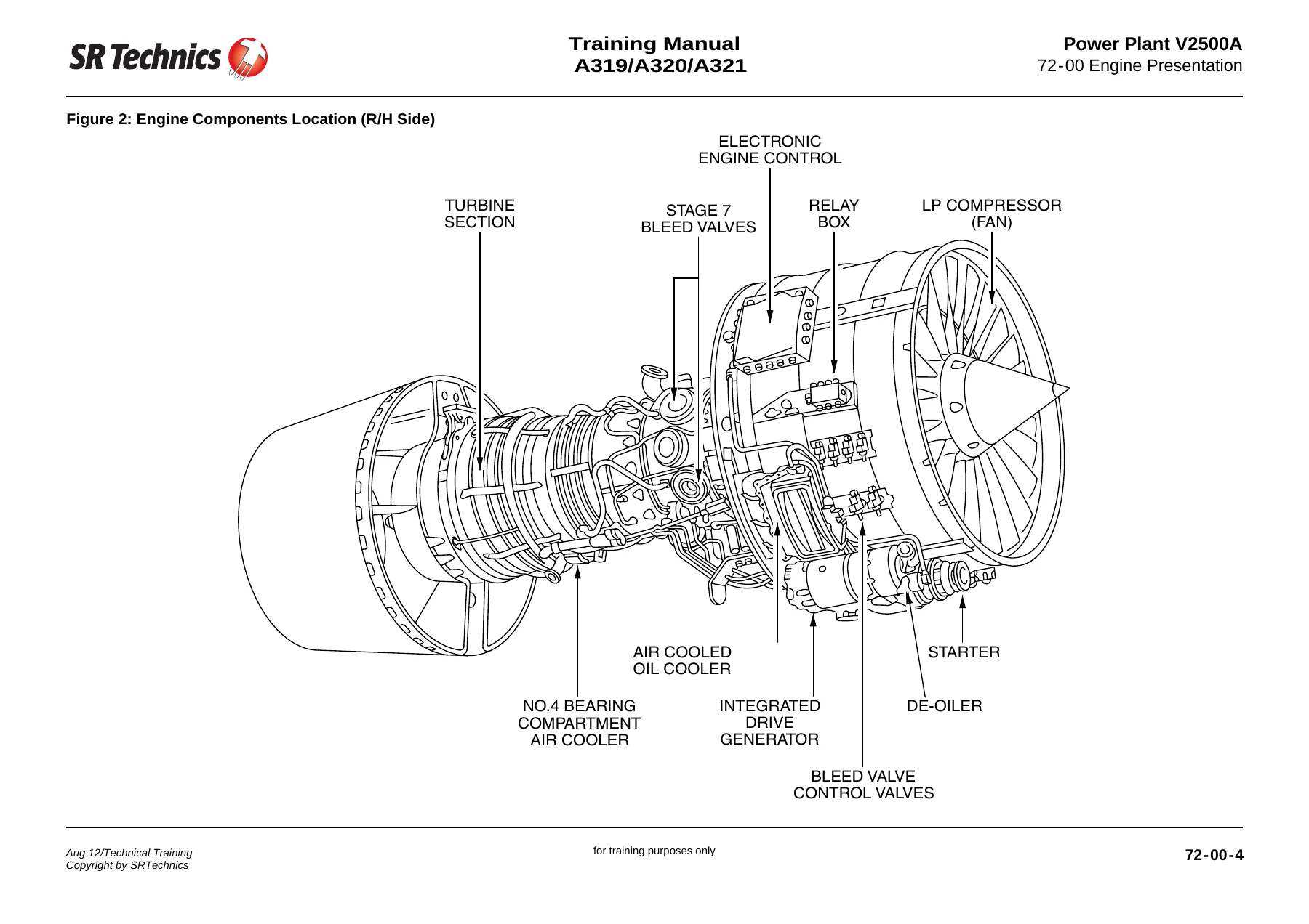
The V2500A powerplant section provides extensive component and gas-path information. It identifies the fan and compressor arrangement, combustion and turbine sections, accessory equipment and the combined nozzle assembly. Left- and right-hand engine illustrations show such components as the fuel-cooled oil cooler, fuel filter, oil tank, pumps, starter, electronic engine control and integrated drive generator. These illustrations are valuable for learning the physical arrangement before studying the individual engine systems.
Further engine subjects address fuel and control, ignition, air, engine controls, indicating, thrust reverser, oil and starting. The V2530-A5 presentation identifies one fan stage, four low-pressure compressor stages, ten high-pressure compressor stages, two high-pressure turbine stages and five low-pressure turbine stages. These are configuration-specific training details; they should not be generalized to every engine mentioned in the aircraft-family comparison.
Using the Diagrams and Comparative Data Effectively
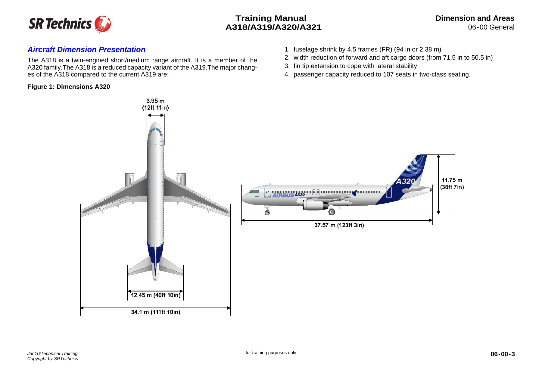
The general aircraft table compares A318, A319, A320 and A321 dimensions and selected weights, capacities and typical seating. It preserves distinctions such as fuselage length and the different values assigned to each model. This gives students a useful starting point for understanding the family, while the system and engine chapters provide the deeper component-level material. The table values belong to the configurations represented in the training source, rather than serving as universal limits for all aircraft carrying those model names.
For focused study, begin with the relevant chapter contents and system presentation, then follow the component diagrams and associated functional explanation. A topic such as emergency electrical supply naturally connects to hydraulic power; flap actuation connects to control computers and position indication; and the powerplant diagrams connect to fuel, oil, air and starting chapters. This approach makes the breadth of the compilation practical without losing the boundaries between different systems.
From Basic Architecture to Detailed Component Identification
The electrical introduction illustrates the level of detail available in the source. It names two main transformer rectifiers and an essential transformer rectifier, two batteries with their charge limiters, and the static inverter used for part of the essential AC supply. Generator control and distribution subjects then show how those components fit into the broader system. A reader can therefore begin with the general power sources and progressively identify the equipment appearing in more detailed diagrams.
The same progression is useful in the engine material. External component illustrations orient the reader to the accessory arrangement before the fuel, oil, air and starting sections describe their own equipment. The separate compressor, combustion and turbine presentation supplies the internal gas-path context. Keeping these views together helps distinguish a component location, its system role and the configuration-specific data attached to it, which is the practical value of a detailed technical training reference.
File Details
- Equipment family: Airbus A318, A319, A320 and A321.
- Publisher identified in the pages: SR Technics Technical Training.
- Manual type: EASA Part 66 Level III technical training compilation.
- Language and format: English PDF, 3730 pages.
- Powerplant depth: detailed V2500A training material, with aircraft-family comparisons elsewhere.
- Document scope: training purposes only; individual sections carry their own dates.
Chapters Covered
- General information, abbreviations and aircraft identification.
- Aircraft general, time limits and maintenance-check context.
- Dimensions and areas; lifting and shoring; leveling and weighing.
- Towing and taxiing; parking and mooring; servicing and maintenance practices.
- Air conditioning and autoflight.
- Communications and electrical power.
- Equipment and furnishings; fire protection.
- Flight controls, including flap actuation and monitoring.
- Fuel systems, indication and A321-specific fuel material.
- Hydraulic power, power transfer and ram air turbine.
- Ice and rain protection; indicating and recording.
- Landing gear, lights and navigation.
- Oxygen, pneumatic supply, water and waste.
- Aircraft information-management and fuel-inerting systems.
- Auxiliary power, including APIC APS3200 and comparison subjects.
- Structures: doors, fuselage, nacelles, stabilizers, windows and wings.
- V2500A powerplant presentation and engine component arrangement.
- Engine fuel and control, ignition, air and controls.
- Engine indicating, thrust reverser, oil and starting.
Keep a Detailed A320-Family Study Reference Available
This PDF brings a large body of aircraft and engine training material into one accessible reference. It supports system familiarization, component identification and structured technical revision while retaining the source’s training-only status and model distinctions. Instant PDF delivery after payment avoids shipping time; use a compatible PDF reader for study and print selected diagrams or reference pages when a paper copy is helpful.
Reviews
There are no reviews yet.