
Swearingen Merlin IIB SA-26AT Aircraft Systems Training Manual PDF
Original price was: $32.95.$18.95Current price is: $18.95.
Swearingen Aviation training manual covering description and operating principles for the Merlin IIB Model SA-26AT: airframe systems, Garrett/AiResearch TPE 331-1-151G powerplants, Hartzell reversible props, pressurization, Freon cooling, and oxygen.
Description
Swearingen Merlin IIB SA-26AT Aircraft Systems Training Manual PDF
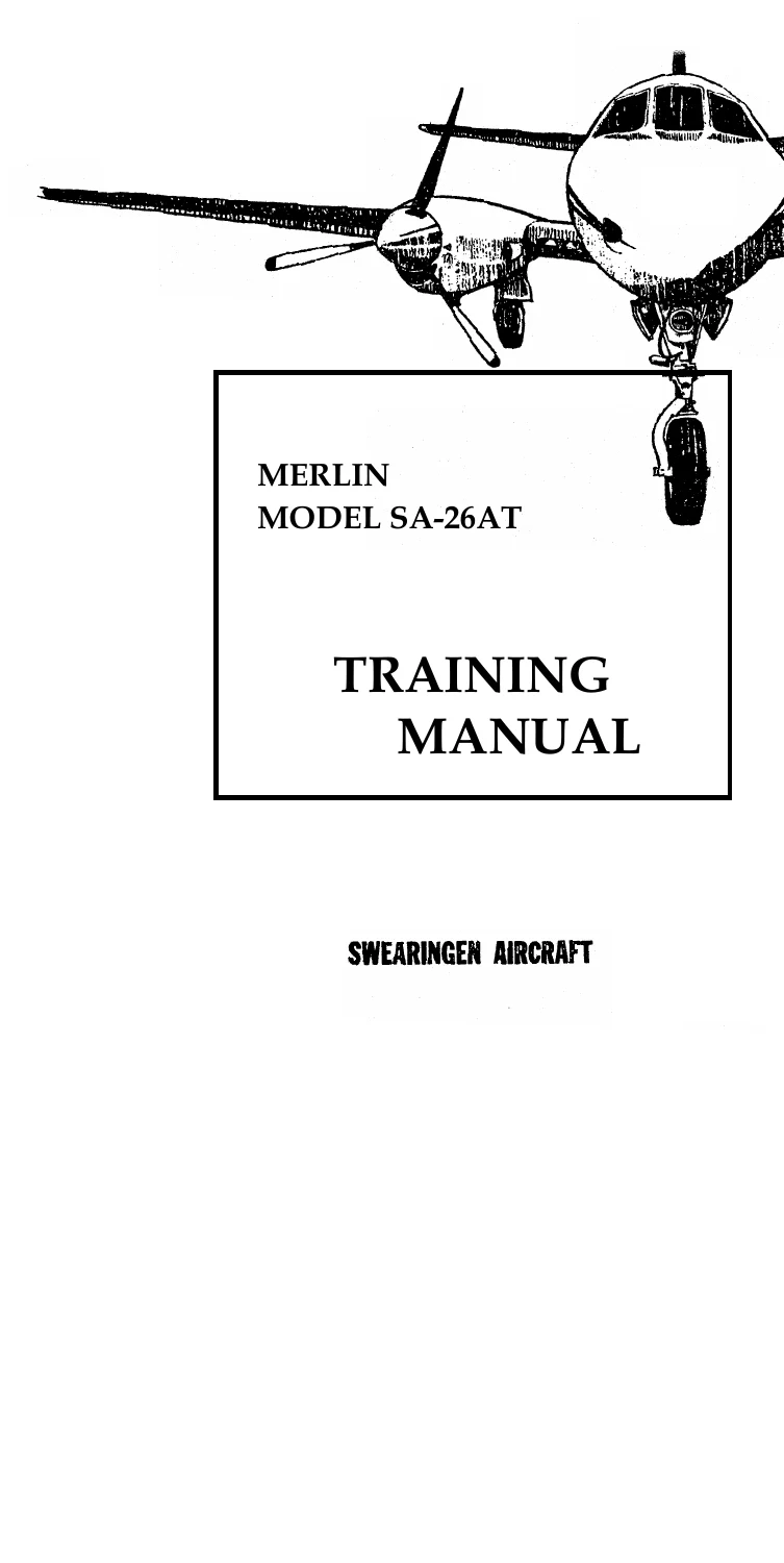
This Swearingen Merlin IIB SA-26AT Aircraft Systems Training Manual PDF is Swearingen Aviation Corporation course material on description and operating principles for the pressurized Merlin IIB, Model SA-26AT. It was prepared from the basic aircraft design and is written for school and shop study of how the airframe, electrical buses, flight controls, landing gear, de-ice gear, TPE 331 powerplants, and environmental systems are put together and how they work. The introduction states that the material neither supersedes nor supplements official publications. For complete coverage the reader is sent to the Merlin IIB Maintenance Manual, the Merlin IIB Illustrated Parts Catalog, the AiResearch TPE 331-1-151G Maintenance Manual, and the AiResearch TPE 331-1-151G Illustrated Parts Breakdown.
File Details
- Manual type: Aircraft systems training manual (description and operating principles)
- Brand / model: Swearingen Aviation Corporation — Merlin IIB, Model SA-26AT (also printed SA26AT)
- Engines: Two Garrett/AiResearch TPE 331-1-151G fixed-shaft turboprops
- Language: English
- Page count: 362
- File format: PDF
Aircraft Covered in This Training Book
General information in the Swearingen Merlin IIB SA-26AT Aircraft Systems Training Manual PDF describes an 8–10 place pressurized executive airplane with dual controls, a low-wing all-metal airframe, full cantilever wing and tail, semi-monocoque fuselage, and fully retractable tricycle landing gear. The cabin is designed for a normal operating pressure of 7.0 psi. The pressure vessel is proof tested to 9.64 psi and is built to take pressurization between stations #51.31 and #406.56. Final assembly mates a nose section, a constant section of four quarter panels, and a tail section. Empennage flight-control runs are enclosed inside the pressure vessel so cable seals are not required at the tail.
The jet-type cylindrical fuselage is described as fail-safe construction using multiple load paths, low stress levels, and slow-crack-growth material. Six 17 × 22 inch dry-air sandwich windows sit in the passenger cabin. The airstair door measures 26 × 64 inches on the left; the emergency exit is 19 × 26 inches on the right. The three-piece windshield uses electrically heated flat glass in front of each pilot and a stretched-acrylic center panel. Pilot side windows and cabin panes are stretched acrylic. The radome nose cap is fiberglass honeycomb sized for an 18 inch antenna. Baggage, clothes rack, snack bar, and lavatory occupy the aft cabin.
Wings and center section originate from Beech Twin Bonanza or Queen Air series hardware remanufactured by Swearingen. All fuel is carried in the wings after conversion to integral tanks. Header tanks in the center section feed the engines. Tank areas are treated with PRI560M then sealed with PRI422A2 or B2. Horizontal controls (ailerons, flaps, stabilizer, elevators) are likewise remanufactured Beech items; the vertical stabilizer, dorsal fin, and rudder are Swearingen-built. Controls are aerodynamic and mass balanced and are flown from dual cockpit stations.
Chapters Covered
- Introduction and general information (airframe, fuselage, wing, controls, landing gear, interior)
- Section One — Basic Aircraft and Aircraft Related Systems
- Structure repair, sealing, main cabin entrance door (seven patented latch assemblies)
- Cockpit and cabin windows; stretched acrylic care, polish, and inspection limits; electrically heated glass windshields
- Approved antenna locations; cockpit instruments and controls
- Electrical system: buses, generator overload and overvoltage, start system, starter-generators, batteries and relays, propeller unfeather pump
- Flight controls: aileron, rudder, elevator, trim tabs, elevator down spring, cable tension vs. temperature, control travel limits
- Flap drive and flap electrical schematic
- Landing gear retract system, gear/flap position indication, nose-gear steering, turn radius and limits
- Main wheel brake system and main landing gear wheels
- Surface de-icer boot system and distributor valve; propeller de-icing (de-icers, slip rings, timer, resistance checks)
- Windshield heat, windshield wiper system, cockpit de-fog
- Stall warning, cabin altitude warning, cabin door warning
- Pitot/static system
- Section Two — Power Plants and Related Systems
- Basic engine description; engine installation, vibration mounts, accessory mount torque limits
- Hartzell propeller installation, removal, spinner/de-icer platter, lubrication
- Power lever, R.P.M. lever, beta light, engine stop and feather, intake heat, chip detector
- Propeller synchronization (components, flight procedures, functional test)
- Turbine inlet temperature system; torque sensing and negative torque; percent R.P.M. and engine speed switch
- Oil system; aircraft fuel system (boost, shut-off, cross flow, quantity rigging, flow, dump, pressure)
- Fire warning; outside air temperature indication
- Section IIA — TPE 331 Turboprop Engine
- Terms and definitions; general information; typical engine limitations
- Introduction to the TPE engine; gas turbine operating cycle; general construction
- Lubrication; power management; fuel system; propeller controls and rigging
- Torque indicator and negative-torque requirement; torque sensor
- Bleed air and anti-ice; engine electrical system; instruments
- Section Three — Reference Tables and Charts (listed in the front table of contents)
- Section Four — Environmental Systems
- Pressurization: pressure supply (TPE 331-1-151G bleed, check valves, mass-flow control valve, heat exchanger, venturi, muffler)
- Pressure control: outflow valve control, cabin outflow and safety valve, cabin air pressure safety valve, manual selector, instruments
- Cabin temperature control (sense elements, selector, control box, heat-exchanger valve)
- Freon air conditioning service, manifold and hose use, leak detection, evacuation, and charging
- Stand-by oxygen system and duration chart
Taken as a whole, the book walks a technician or student through how each major Merlin IIB system is arranged, how cockpit switches and pedestals command those systems, and how the TPE 331-1-151G interfaces with airframe bleed, fuel, oil, electrical, and propeller hardware. School-note pages appear in the front matter for classroom use. Section IIA is presented as the basic training text for the TPE 331 and warns that many pressure, temperature, speed, and power figures in that engine section are chosen for illustration and are not necessarily the certified values for a given engine; the applicable engine maintenance manual is required for actual limits.
IMAGES PREVIEW
Airframe Figures and System Layouts
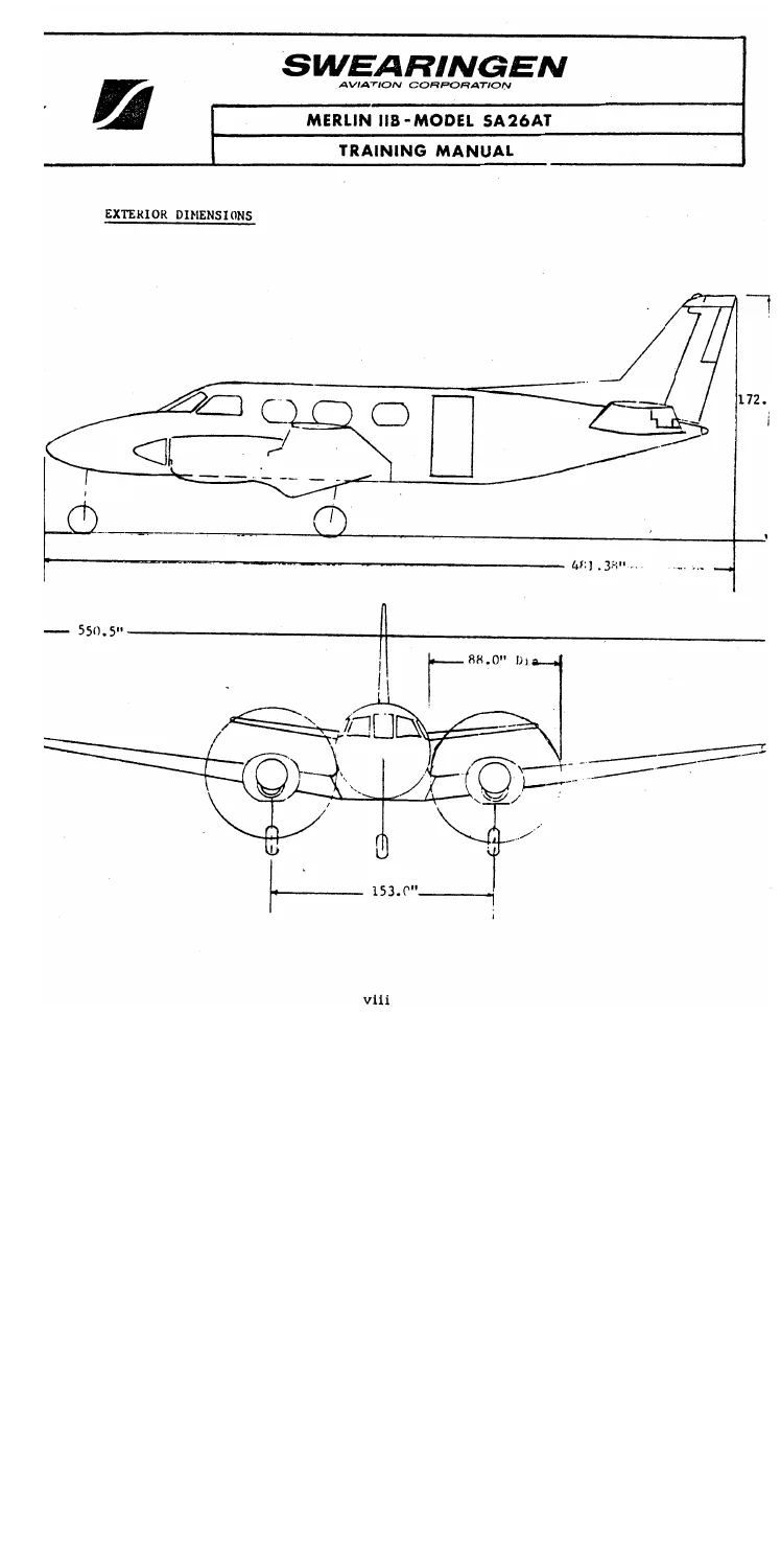
Early pages of the Swearingen Merlin IIB SA-26AT Aircraft Systems Training Manual PDF list airframe dimensions used throughout the course: length 40 ft. 3/8 in., height 14 ft. 13/32 in., span 45 ft. 10.5 in., wing area 279.74 sq. ft., aspect ratio 7.51, mean aerodynamic chord 77.80 in. Cabin figures include 62 in. width, 59 in. height, 255 in. overall cabin length, 57 in. cockpit, and 65 in. lavatory. Design gross weight is 10,000 lb., design empty weight 6,150 lb., landing weight 9,300 lb., ramp weight 10,062 lb., wing loading 35.8 lb/sq. ft., and power loading 7.52 lb/hp. Performance notes include cruise 295 MPH at 15,000 ft., range with 386 gals. of 1785 mi.+ at 27,000 ft., two-engine rate of climb 2,570 ft./min., service ceiling 29,900 ft., single-engine service ceiling 12,500 ft., stall 87 MPH gear and flaps down, and take-off and landing distances over a 50 ft. obstacle of 2,600 ft. each.
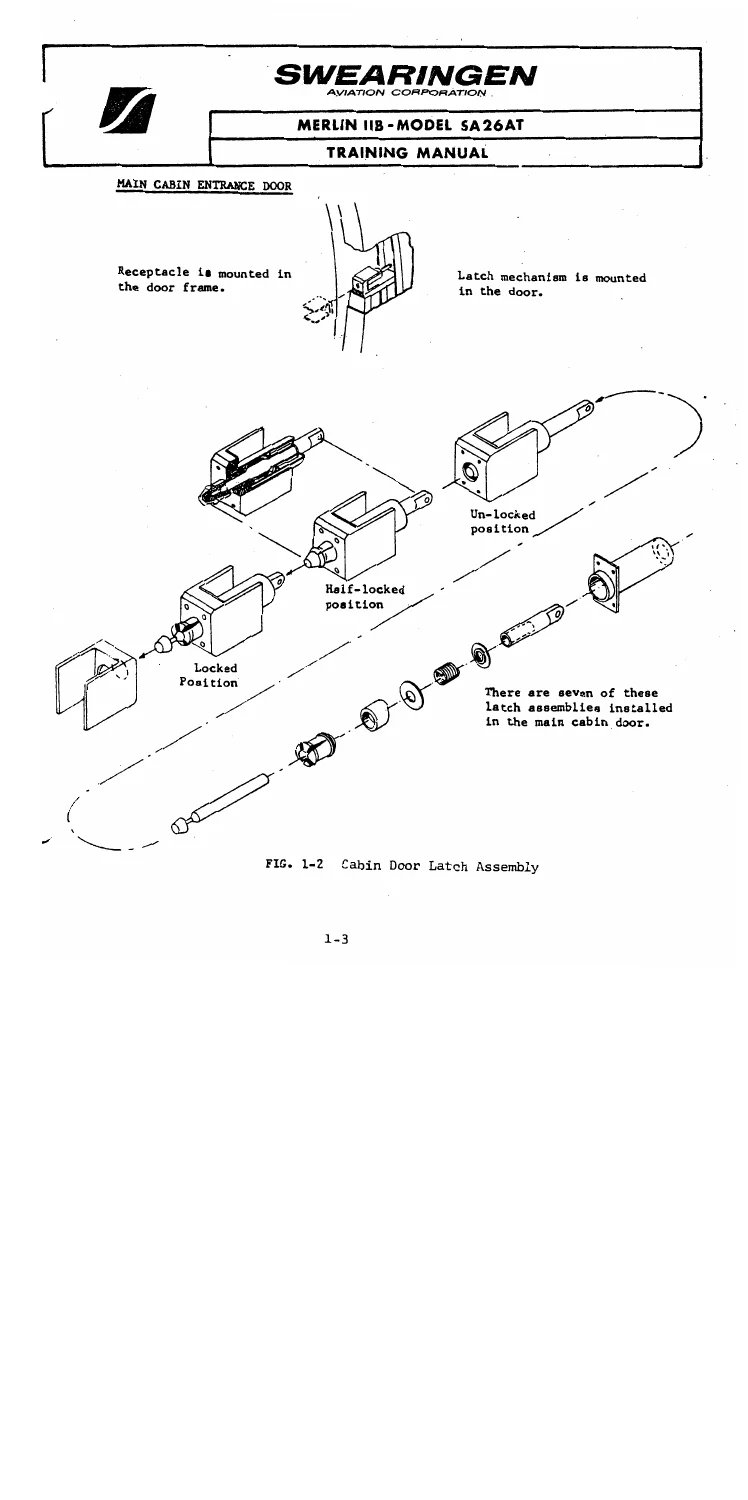
Structure-repair notes send pressurized-area work to Advisory Circular 43.13-1 and 43.13-2 and treat every skin, former, and stringer in the pressure vessel as structure. Sealing calls out PRC PR 1221-A2 (brush) and PR 1221-B2 (injection). The main door uses seven Swearingen patented latches driven by one handle through two stages: bayonet extension into frame receptacles, then plunger expansion of a split barrel. Window inspection text defines craze, star craze, crack, and scratch and gives rejection depths for inner versus outer acrylic panes and for glass windshield scratches, bubbles, and delamination. Heated windshields are Pittsburgh Plate Glass Aircon units with a fine-wire element on the D.C. bus, held at 90–110°F when powered.
Electrical description opens with two essential buses plus a non-essential bus, generator overload and overvoltage protection, and a start system built around starter-generators, series-parallel and start-control relays, an oil vent valve, a propeller unfeather pump, and a battery relay. Lighting is split so pilot flight instruments and map lights live on the left essential bus, co-pilot equivalents on the right essential bus, and remaining cockpit lighting on the non-essential bus. The pedestal groups power and R.P.M. levers, trim wheels, landing-gear and flap handles, parking brake, oxygen and oil-shutter controls, prop-sync, and fuel-management switches.
Landing gear is a single electric motor driving torque shafts, chain, and sprocket, with mechanically operated wheel-well doors and a manual extension path if electrics fail. Struts are air/oil; the nose strut is modified for Swearingen electrical steering on a modified Beech nose gear (P/N 50-820001-9) that remains full-castering when steering is off. Main wheels and self-adjusting hydraulic disk brakes are B.F. Goodrich. Surface de-ice uses a distributor valve cycling boots; propeller de-ice uses timed heater circuits through slip rings and a brush block, with timer and resistance checks in the text. Warning systems cover stall (heated transducer, steady horn about 7–8 MPH above stall), cabin altitude, and the cabin door light. Pitot/static routing and heated masts are drawn at the end of Section One.
Powerplant and Propeller Coverage
Each engine is listed as Garrett/AiResearch TPE 331-1-151G, rated at sea level to 75°F at 665 SHP / 705 ESHP for both take-off and max continuous, with fuel consumption 0.603 lb/ESHP/hr. max., oil consumption 0.02 Gal/hr., and TBO printed as 2,000 hr. with handwritten 3,400 / 3,600 annotations on the spec page. The engine is a fixed-shaft turboprop with compressor, turbine, and reduction-gear sections. The engine oil tank on the reduction-gear housing holds 6.25 U.S. quarts, fed by a pressure pump through filter and regulator and returned by three scavenge pumps. Fuel on the engine side runs through boost and high-pressure pumps, a 40 micron filter, fuel control, solenoid valve (opens near 10 percent engine speed), and a flow divider to primary and secondary nozzles.
Propellers are Hartzell three-blade, full-feathering, reversible units. Power-lever and R.P.M.-lever text explains beta (ground) versus propeller-governing (flight) modes: in beta the pilot selects blade angle and fuel is scheduled automatically; in governing, blade angle is automatic and fuel selection is manual. Negative-torque sensing bypasses governor oil toward feather. Prop sync, TIT (pressure-ratio transducer path), torque indication, percent RPM / speed switch, intake heat, chip detector, fire warning, and OAT (belly resistance bulb, about 5°C frictional rise at cruise) close the airframe-side engine chapter. Section IIA then expands the same engine with construction, lubrication, fuel and propeller controls, rigging, bleed and inlet anti-ice, and typical electrical start/control switches. Compression ratio of the two-stage centrifugal compressor is given as 8.5:1 in the environmental bleed discussion. When the gas generator turns 41,730 R.P.M., the two-stage reduction drives the propeller.
Airframe fuel is stored in integral wing tanks feeding center-section header tanks and submerged boost pumps. A two-inch cross-flow line and valve move fuel side to side. Firewall shut-off switches on the pedestal fuel panel are guarded open. Quantity-system rigging, flow indication, dump, and pressure indication are written as classroom procedures rather than as a substitute for the maintenance manual.
Pressurization, Cooling, and Oxygen
Section Four of the Swearingen Merlin IIB SA-26AT Aircraft Systems Training Manual PDF treats environmental systems as a separate course block. Bleed air from both TPE 331-1-151G engines supplies cabin flow and heat. Engine rules forbid bleed extraction during start, so the control circuit is wired through generator parallel-relay contacts and mixing-valve microswitches: Freon compressor operation needs both engines running and both generators on the line, with the mixing valve at full cold; ground heat needs the mixing valve at full hot plus both generators on the line so the bleed shut-off can open without stealing start air. After lift-off a main-gear strut switch lets the mass-flow control valve open.
Pressure control uses an outflow-valve controller (set to airport elevation for takeoff), cabin outflow and safety valves, a cabin air pressure safety valve, and a manual selector. A minimum 0.5 inch Hg differential across the outflow diaphragm is required to go on control. Isobaric bellows and metering raise cabin pressure with altitude until the 7.0 psi maximum differential is reached. Cabin temperature control uses outside-air, supply-duct, and cabin-air sense elements plus a selector and control box driving the heat-exchanger valve. Freon service pages cover manifold gauges, hoses, service valves, leak detection, abnormal gauge readings, evacuation with a vacuum pump or with the compressor used as a pump, and the filling procedure.
A stand-by oxygen system is standard. A 22 cu. ft. bottle in the unpressurized nose carries regulator, shut-off, and an external service fitting behind the left nose access door. An Arens control on the pedestal turns the system on and off. Outlets exist at every seat including the lavatory. Passenger masks are disposable units in seat-back pockets; crew masks are permanent types stored under the crew chairs with smoke goggles and deliver twice the passenger flow because the orifice is in the bayonet. The bottle is normally serviced to 1800 psi and is stated to supply 8 people for one half hour; an oxygen-duration curve is printed against number of persons.
Use This Manual for System Study and Checkout
The Swearingen Merlin IIB SA-26AT Aircraft Systems Training Manual PDF supports classroom and hangar study of how the SA-26AT is built and how its systems interact: door latching and pressure-vessel sealing, acrylic and heated-glass window limits, essential versus non-essential electrical routing and start/generator logic, cable and electric flight-control and flap paths, gear and nose-steering rigging, brake and wheel hardware, boot and propeller de-ice timing and resistance checks, warning and pitot/static layout, TPE 331-1-151G installation and cockpit control modes, fuel and oil routing, TIT and torque sensing, bleed-air pressurization to 7.0 psi, Freon service steps, and the 22 cu. ft. oxygen bottle. Correct description of bus interlocks, bleed-extraction inhibits, beta versus governing, and outflow-valve control matters because those details are how this airframe was designed to keep start air, cabin flow, and propeller pitch from fighting each other.
Download is instant after purchase. You receive the PDF to use on any device and to print the figures and schematics you need — no shipping delay.
Reviews
There are no reviews yet.