Description
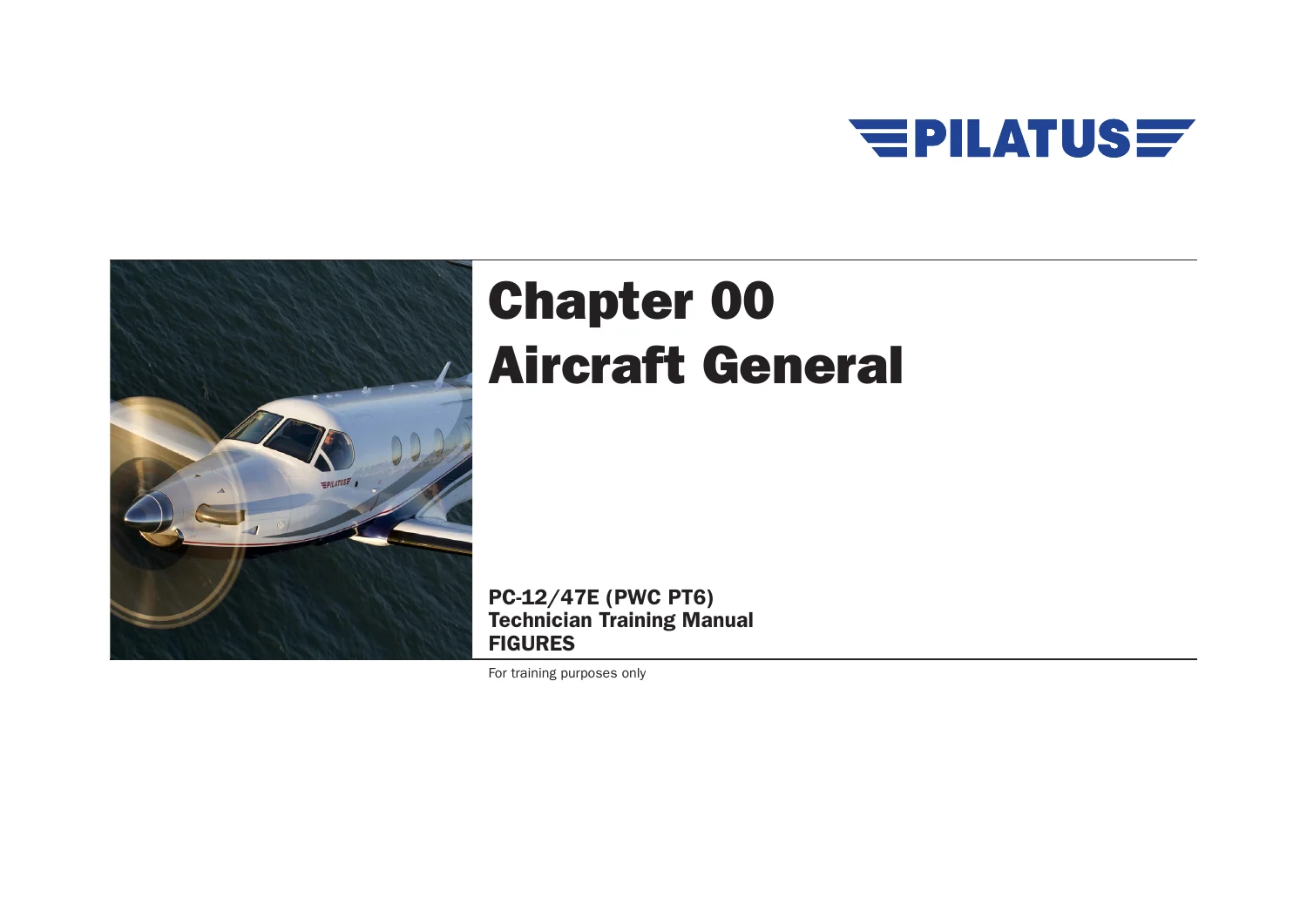
Pilatus PC-12/47E PWC PT6 Technician Training Manual Figures & Notes – Issue 7 (2016)
The Pilatus PC-12/47E PWC PT6 Technician Training Manual Figures & Notes – Issue 7 (2016) is a large-format technical training reference built around the PC-12/47E aircraft and its systems. Across 1163 PDF pages, the publication combines system figures, schematics, component-location illustrations, controls and indication diagrams, technical notes, operating descriptions, safety material and training-oriented explanations. The aircraft introduction identifies the Pratt & Whitney Canada PT6A-67P turboprop engine, while the later engine chapters break the powerplant into its reduction gearbox, compressor, combustion, turbine and accessory sections.
This is much broader than a single-system booklet. It moves from basic aircraft layout and ground handling into environmental control, autoflight, communications, electrical power, furnishings, fire protection, flight controls, fuel, hydraulics, ice protection, indicating systems, landing gear, navigation, oxygen, central maintenance, structures, propeller and engine subjects. The figures are especially useful for understanding where components sit in the aircraft and how individual systems connect to controls, sensors, valves, actuators, buses and cockpit indications.
Training Use and Document Status
This publication is explicitly marked For training purposes only. The preliminary pages state that it is not updated, no amendment service is provided, and its intended use is training only; it may not be used for maintenance or repairs on the related aircraft. The chapter notices also state that the information does not replace the manufacturer’s maintenance documents. It is therefore suited to system familiarization, classroom study, recurrent technical review and visual understanding of the PC-12/47E, while current approved maintenance data must be used for actual aircraft maintenance or repair work.
Issue 7 is dated 31/05/2016. The document issue record states that this issue incorporates Model Year 2016 changes, following earlier updates to individual systems and chapters.
File Details
- Manual type: Technician Training Manual – Figures and Notes
- Brand / model: Pilatus PC-12/47E (PWC PT6)
- Engine identified in the manual: Pratt & Whitney Canada PT6A-67P
- Issue: Issue 7
- Date: 31/05/2016
- Language: English
- Page count: 1163 pages
- File format: PDF
- Document status: For training purposes only
Chapters Covered
- 00 Air Vehicle
- Aircraft Introduction
- Aircraft Documentation
- Electrostatic Devices and Handling
- Safety Introduction
- 06 Dimensions and Areas
- Dimensions and Zones
- Access Panels
- 07 Lifting and Shoring
- 08 Levelling and Weighing
- 09 Handling and Taxiing
- 10 Parking, Mooring and Storing
- 11 Placards and Markings
- 12 Servicing
- 20 Standard Practices
- Locking and Retaining Devices
- Torque Wrenches and Procedures
- Consumable Materials List
- Corrosion
- 21 Air Conditioning
- Distribution
- Pressurization Control
- Heating and Cooling
- Additional Cooling
- Temperature Control
- 22 Auto Flight
- Autopilot
- Speed and Attitude Correction
- 23 Communications
- 24 Electrical Power
- 25 Equipment and Furnishings
- 26 Fire Protection
- 27 Flight Controls
- Aileron Control System
- Rudder Trim
- Elevator Control System
- Horizontal Stabilizer Trim
- 28 Fuel
- Storage
- Distribution
- Fuel Balancing System
- Indicating
- 29 Hydraulics
- 30 Ice and Rain Protection
- 31 Indicating and Recording Systems
- 32 Landing Gear
- 33 Lights
- 34 Navigation
- 35 Oxygen
- 45 Central Maintenance System
- 46 Systems Integration and Display
- 52 Doors
- 53 Fuselage
- 55 Stabilizers
- 56 Windows
- 57 Wings
- 61 Propellers
- 71 Power Plant
- 72 Engine
- Reduction Gearbox
- Air Inlet Section
- Compressor Section
- Combustion Section
- Turbine Section
- Accessory Gearbox
- 73 Engine Fuel and Control
- 74 Ignition
- 75 Air
- 76 Engine Controls
- 77 Engine Indicating
- 78 Exhaust
- 79 Oil
- 80 Starting
Taken together, these chapters give technicians a system-by-system training path from aircraft orientation through major mechanical, electrical, avionics and powerplant subjects. The manual repeatedly combines descriptive notes with figures showing component locations, flow paths, controls, cockpit indications and system logic, making it useful when the objective is to understand how the PC-12/47E is organized rather than simply memorize component names.
Aircraft and Ground-Servicing Reference
The opening material explains aircraft configurations, underfloor equipment layout, antenna locations, manual numbering, wire identification and ESD handling. Dimension and access-panel sections show structural frames, wing and stabilizer ribs, primary and secondary zones, and maintenance access locations. Ground-oriented chapters illustrate complete-aircraft lifting, wheel jacking, weighing and levelling, towing equipment, turning-radius information, parking protection and mooring points.
The servicing material covers fuel replenishment and defueling concepts, brake fluid, engine oil, tire information, oxygen replenishment, exterior and interior cleaning, landing-gear servicing, propeller care and wheel-bearing servicing. Standard-practices training adds locking devices, torque-wrench principles, consumable-material references and corrosion awareness. These sections provide useful context for recognizing servicing points, hardware practices and safety considerations before a technician consults the applicable current maintenance instructions for an actual task.
Systems, Avionics and Flight-Control Training
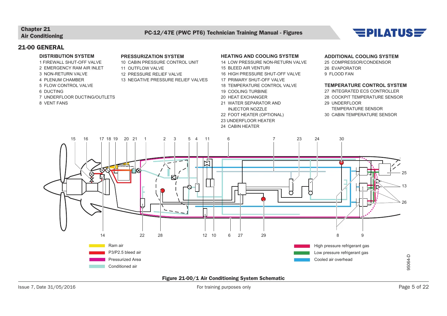
Major aircraft systems are presented with detailed visual logic. The Environmental Control System material includes distribution, cabin pressurization, air-cycle heating and cooling, auxiliary heaters, optional vapour-cycle cooling and automatic temperature control. The Auto Flight chapter covers the Automatic Flight Control System, pitch, roll and yaw servo actuators, trim functions, flight-director modes and the speed-and-attitude correction system with stick shaker and stick pusher components.
Communications, navigation, electrical power, central maintenance and systems-integration chapters provide further cockpit-to-system context. The manual also dedicates substantial coverage to flight controls, fuel storage and distribution, hydraulic power, ice and rain protection, landing gear, lighting, oxygen, doors and structural areas. Many figures identify individual components and their installation positions, while schematics show signal or fluid paths and system interrelationships.
Complete PDF Bookmark Tree
Complete Bookmarks
The complete bookmarks in the “Pilatus PC-12/47E PWC PT6 Technician Training Manual Figures & Notes – Issue 7 (2016)” are as follows:
+PC-12/47E (PWC PT6) TTM FIGURES
TABLE OF CONTENTS
DOCUMENT ISSUE RECORD
+Chapter 00 Aircraft Generalp. 1
+00-03 AIRCRAFT INTRODUCTION
Figure 00-03/1 Aircraft General – Configurations Features
Figure 00-03/2 Interior Configurations
Figure 00-03/3 Underfloor Layout
Figure 00-03/4 Antenna Layout
+00-04 AIRCRAFT DOCUMENTATION
Figure 00-04/1 Wire Numbering – Example
Figure 00-04/2 Wiring Diagram Manual – Example
+00-05 ELECTROSTATIC DEVICES AND HANDLING
Figure 00-05/1 Anti-static Wrist Strap and ESD Symbol
+00-06 SAFETY INTRODUCTION
Figure 00-06/1 Ignition System – Safety
Figure 00-06/2 Hydraulic – Safety
Figure 00-06/3 High Intensity Lights – Safety
+Chapter 06 Dimensions and Areas
+06-10 DIMENSIONS AND ZONESp. 3
Figure 06-10/1 Principle Dimensionsp. 3
Figure 06-10/2 Structure Identification
Figure 06-10/3 Aircraft Primary Zones
Figure 06-10/4 Aircraft Secondary Zones
+06-20 ACCESS PANELS
Figure 06-10/1 Access Panels – Fuselage left and right side
Figure 06-10/2 Access Panels – Fuselage lower side
Figure 06-20/3 Access Panels – Wing lower side
+Chapter 07 Lifting and Shoring
+07-00 GENERAL
Figure 07-00/1 Lifting Complete Aircraft
Figure 07-00/2 Jacking Nose or Main Wheel
+Chapter 08 Leveling and Weighing
+08-00 GENERAL
Figure 08-00/1 Weighing and Leveling
+Chapter 09 Towing and Taxiing
+09-00 GENERAL
Figure 09-00/1 Towing Equipment
Figure 09-00/2 Ground Turning Radius – With NWS, Inside Brake and Partial Powerp. 6
Figure 09-00/3 Ground Turning Radius – With NWS and Partial Power
+Chapter 10 Parking and Mooring
+10-00 GENERAL
Figure 10-00/1 Parking 1
Figure 10-00/2 Parking 2
Figure 10-00/3 Mooring Points
+Chapter 11 Placards and Markings
+11-00 GENERAL
Figure 11-00/1 Exterior Placards and Markings – Example
Figure 11-00/2 Interior Placards and Markings – Example
+Chapter 12 Servicing
+12-00 GENERAL
Figure 12-00/1 Fuel System – Refueling
Figure 12-00/2 Fuel System – Defueling
Figure 12-00/3 Tire Wear Indicators
Figure 12-00/4 Oxygen System Replenishment
Figure 12-00/5 Aircraft Exterior Cleaning Sections
Figure 12-00/6 Nose Landing Gear Bearing Replenishment
Figure 12-00/7 Main Landing Gear Bearing Replenishment
+Chapter 20 Standard Practicesp. 9
+20-20 LOCKING AND RETAINING DEVICES
Figure 20-20/1 Locking and Retaining Devices – Example from AMM
+20-20-01 TORQUE WRENCHES AND PROCEDURES
Figure 20-20-01/1 Standard Torque Values and Torque Wrenches with Extensions
+20-31 CONSUMABLE MATERIALS LIST
Figure 20-31/1 Consumable Material List – Example from AMM
+20-40 CORROSION
Figure 20-40/1 Corrosion Severity Maps 1
Figure 20-40/2 Corrosion Severity Maps 2
+Chapter 21 Air Conditioning
+21-00 GENERAL
Figure 21-00/1 Air Conditioning System Schematic
Figure 21-00/2 Air Conditioning – Controls and Indication
+21-20 DISTRIBUTION
Figure 21-20/1 Distribution – Overview
+21-30 PRESSURIZATION CONTROL
Figure 21-30/1 Pressurization Control – Overview
Figure 21-30/2 PC-12/47E Cabin/Aircraft Pressure Differential Chart (A) and Relative Atmosphere Pressure Chart (B)
Figure 21-30/3 Cabin Altitude at Maximum Differential Pressure Chartp. 10
Figure 21-30/4 Pressurization Control – Controls and Indication
Figure 21-30/5 Pressurization Control – Schematic
+21-40 HEATING AND COOLING
Figure 21-40/1 Air Cycle System – Layout
Figure 21-40/2 Air Cycle System – Location
Figure 21-40/3 Air Cycle System – Schematic
Figure 21-40/4 Auxiliary Heater System – Schematic
+21-50 ADDITIONAL COOLINGp. 11
Figure 21-50/1 Vapour Cycle Cooling System – Layoutp. 11
Figure 21-50/2 Compressor/Condenser Assembly – Location
Figure 21-50/3 Vapour Cycle Cooling System – Electrical Schematic
Figure 21-50/4 Vapour Cycle Cooling System – Hydromechanical Schematic
+21-60 TEMPERATURE CONTROL
Figure 21-60/1 Temperature Control – Schematic
+Chapter 22 Auto Flight
+22-10 AUTOPILOT
Figure 22-10/1 Auto Flight Control Panel – Location
Figure 22-10/2 Trim Adapter – Location
Figure 22-10/3 Pitch Servo-Actuator – Installation
Figure 22-10/4 Roll Servo-Actuator – Installation
Figure 22-10/5 Yaw Servo-Actuator – Installation
Figure 22-10/6 Autopilot – Controls
Figure 22-10/7 Autopilot – Schematic
+22-20 SPEED AND AtTITUDE CORRECTION
Figure 22-20/1 Stick Pusher Computer – Location
Figure 22-20/2 Stick Pusher Servo/Capstan – Installationp. 13
Figure 22-20/3 Stick Shaker Actuator – Location
Figure 22-20/4 Torque Transducer – Location
Figure 22-20/5 Stick Pusher System – Controls and Indication
Figure 22-20/6 Stick Pusher System – Schematic
+Chapter 23 Communicationp. 15
+23-12 VHF COMMUNICATION SYSTEM
Figure 23-12/1 VHF Com System – Controls
Figure 23-12/2 Multi Mode Digital Radio – Location
Figure 23-12/3 VHF Com Antenna – Installations
Figure 23-12/4 VHF Com System – Schematic
Figure 23-12/5 VHF Com System – Displays
+23-16 SATCOM SYSTEM
Figure 23-16/1 SATCOM Antenna Locations and Inmarsat SATCOM System
+23-50 AUDIO INTEGRATING SYSTEM
Figure 23-50/1 Audio Control Panel
Figure 23-50/2 Audio Integrating System – Schematic
+23-60 STATIC DISCHARGING
Figure 23-60/1 Static Dischargers – Installation
Figure 23-60/2 Static Discharger – Operation
+Chapter 24 Electrical Power
+24-00 GENERAL
Figure 24-00/1 Electrical Power System – Basic Schematic
+24-30 DC GENERATION
Figure 24-30/1 DC Generation and Distribution Systems – Schematic
Figure 24-30/2 Generator 1 – Installation
Figure 24-30/3 Starter/Generator 2 – Installation
Figure 24-30/4 Generator Control Unit 1 – Installationp. 18
Figure 24-30/5 Generator Control Unit 2 – Installation
Figure 24-30/6 Battery 1+2 – Installation
Figure 24-30/7 LH Power Junction Box – Installation
Figure 24-30/8 RH Power Junction Box – Installation
Figure 24-30/9 Battery and External Power Junction Box – Installation
Figure 24-30/10 Electrical Power Controls – Overhead Control Panel
Figure 24-30/11 Generator 1 System – Schematic
Figure 24-30/12 Generator 2 System – Schematic
Figure 24-30/13 Battery 1+2 Systems – Schematic
Figure 24-30/14 Bus Tie System – Schematic
Figure 24-30/15 Generator and Battery – Indications
Figure 24-30/16 Electrical System Normal Operation – Both Generators On-Line – Schematic
Figure 24-30/17 Electrical System Abnormal Operation – Generator 1 Off – Schematic
Figure 24-30/18 Electrical System Abnormal Operation – Generator 2 Off – Schematic
+24-40 EXTERNAL POWER
Figure 24-40/1 External Power Receptacle – Installation
Figure 24-40/2 External Power Control Switch and LED Indication – Installation
Figure 24-40/3 External Power System – Schematic
+24-50 LOAD DISTRIBUTION
Figure 24-50/1 Load Distribution Systems Layout – Schematic
Figure 24-50/2 CB Panel LH Side – Installation
Figure 24-50/3 CB Panel RH Side – Installation
Figure 24-50/4 Av 1 Bus and Standby Bus Systems – Schematic
Figure 24-50/5 Av 2 Bus, Main Bus, Non Ess Bus and Cabin Bus Systems – Schematic
+24-52-51 EMERGENCY POWER SUPPLY
Figure 24-52-51/1 Emergency Power Supply System – Schematic
Figure 24-52-51/2 EPS Unit – Installation
Figure 24-52-51/3 EPS – Controls
Figure 24-52-51/4 Electrical System Emergency Operation – EPS – Schematic
+Chapter 25 Equipment and Furnishings
+25-10 FLIGHT COMPARTMENT
Figure 25-10/1 Flight Compartment Layout
Figure 25-10/2 Flight Compartment Crew Seat
Figure 25-10/3 Flight Compartment Trim Panels
Figure 25-10/4 Flight Compartment Storage Boxes
+25-20 PASSENGER COMPARTMENT
Figure 25-20/1 Passenger Compartment Layouts
Figure 25-20/2 Bench Seat
+25-21 EXECUTIVE INTERIOR
Figure 25-21/1 Executive Interior Layout
Figure 25-21/2 Left Storage Cabinetp. 21
Figure 25-21/3 Right Storage Cabinet and Toilet
Figure 25-21/4 Toilet Compartment – Electrical Schematic
+25-22 STANDARD INTERIORp. 22
Figure 25-22/1 Standard Interior Layoutp. 22
Figure 25-23/1 Standard Baggage Net
Figure 25-23/2 Large Baggage Net
+25-50 CARGO COMPARTMENTp. 23
Figure 25-50/1 Cargo Netp. 23
+25-63 EMERGENCY LOCATOR TRANSMITTER
Figure 25-63/1 ELT System – Schematic
Figure 25-63/2 ELT and NAV Interface – Location
Figure 25-63/3 ELT Antenna – Locationp. 24
+25-90 COLD WEATHER PREHEATER SYSTEM
Figure 25-90/1 Cold Weather Preheater System
Figure 25-90/2 Nose Case Preheater System
Figure 25-90/3 Oil Sump Preheater Systemp. 25
Figure 25-90/4 FCU Preheater System
Figure 25-90/5 110VAC Battery Preheater System
Figure 25-90/6 230VAC Battery Preheater Systemp. 26
+Chapter 26 Fire Protection
+26-10 FIRE/OVERHEAT DETECTION
Figure 26-10/1 Fire Wire – Installation
Figure 26-10/2 FIRE WARN Test Switch – Location
Figure 26-10/3 Fire/Overheat Detection System – Schematicp. 32
+26-20 EXTINGUISHING
Figure 26-20/1 Fire Extinguisher – Location
+Chapter 27 Flight Controlsp. 34
+27-00 GENERAL
Figure 27-00/1 Flight Controls – Overview
+27-10 AILERON CONTROL SYSTEM
Figure 27-10/1 Aileron System – Layout
Figure 27-10/2 Aileron/Rudder Interconnection and Bellcranksp. 36
Figure 27-10/3 Pitch and Roll Controls – Cockpit
+27-15 AILERON TRIM
Figure 27-15/1 Aileron Trim Actuator – Location
Figure 27-15/2 Aileron Trim – Indicationp. 37
Figure 27-15/3 Aileron Trim – Schematic
+27-20 RUDDER CONTROL SYSTEM
Figure 27-20/1 Rudder Control System – Layout
+27-25 RUDDER TRIMp. 38
Figure 27-25/1 Rudder Trim Actuator – Locationp. 38
Figure 27-25/2 Rudder Trim – Indication
Figure 27-25/3 Rudder Trim System – Schematic
Figure 27-25/4 Rudder Trim Controlp. 39
+27-30 ELEVATOR CONTROL SYSTEM
Figure 27-30/1 Elevator Control System – Layout
Figure 27-30/2 Elevator Rear Installation Details
+27-40 HORIZONTAL STABILIZER TRIMp. 40
Figure 27-40/1 Pitch Trim Actuator – Locationp. 40
Figure 27-40/2 Pitch Trim – Indication
Figure 27-40/3 Pitch Trim – Schematic
Figure 27-40/4 ALT Pitch Trim – Schematicp. 41
+27-50 FLAPS
Figure 27-50/1 Flap System – Layout
Figure 27-50/2 Flap Position Selector Transmitter – Installation
Figure 27-50/3 Flap Power Drive Unit – Installationp. 42
Figure 27-50/4 Flap Extend/Retract Mechanism
Figure 27-50/5 Flap Actuator – Installation
Figure 27-50/6 Flap Position Sensors – Installationp. 43
Figure 27-50/7 Flap Limit Switches – Installation
Figure 27-50/8 Flap Indication
Figure 27-50/9 Flap System – Schematic
+27-70 GUST LOCK
Figure 27-70/1 Gust Lock – Installation
+Chapter 28 Fuel
+28-00 GENERAL
Figure 28-00/1 Fuel System – Layout
+28-10 STORAGE
Figure 28-10/1 Fuel Tanks
+28-20 DISTRIBUTION
Figure 28-20/1 Transfer Jet Pump – Installation
Figure 28-20/2 Delivery Jet Pump – Installation
Figure 28-20/3 Fuel Compartment – Layout
Figure 28-20/4 Fuel Filterp. 46
Figure 28-20/5 Engine Driven Pump – Low Pressure
Figure 28-20/6 Fuel Booster Pump – Installation
Figure 28-20/7 Fuel Booster Pump Switches – Locationp. 47
Figure 28-20/8 Flapper Valve – Installation
Figure 28-20/9 Fuel Distribution – Schematic
+28-21 FUEL BALANCING SYSTEM
Figure 28-21/1 Fuel Balancing System – Schematic
+28-40 INDICATING
Figure 28-40/1 Fuel Indicating – Schematic
Figure 28-40/2 Fuel Probes and Low Level Sensors – Installation
Figure 28-40/3 Fuel Control and Monitoring Unit – Location
Figure 28-40/4 Fuel Flow Transmitter – Locationp. 48
Figure 28-40/5 Fuel System Window – Indication
+Chapter 29 Hydraulics
+29-00 GENERAL
Figure 29-00/1 Hydraulic System Overview
+29-10 MAIN HYDRAULIC SYSTEM
Figure 29-10/1 Main Hydraulic System – Layout
Figure 29-10/2 Reservoir Tank, Power Package and Service Tray – Location
Figure 29-10/3 Power Pack – Components
Figure 29-10/4 Power Package and Service Tray Assembly – Bottom View
Figure 29-10/5 Low Pressure Switch and System Pressure Switch – Location
Figure 29-10/6 Main Hydraulic System – Electrical Schematic
Figure 29-10/7 Hydraulic Caution – Schematic
+29-20 EMERGENCY HYDRAULIC SYSTEMp. 51
Figure 29-20/1 Emergency Hand Pump – Installationp. 51
Figure 29-20/2 Emergency Hydraulic System – Schematic
+Chapter 30 Ice and Rain Protection
+30-10 AIRFOIL DE-ICE
Figure 30-10/1 Airfoil De-Ice System – Layout
Figure 30-10/2 Airfoil De-Ice System – Controls and Indication
Figure 30-10/3 Airfoil De-Ice System – Schematicp. 53
+30-20 AIR INTAKE DE-ICING
Figure 30-20/1 Air Intake De-Ice System and Inertial Separator System – Layout
Figure 30-20/2 Air Intake De-Ice System – Controls and Indication
Figure 30-20/3 Air Intake De-Ice System – Schematic
+30-30 PROBES DE-ICE
Figure 30-30/1 Probes De-Ice System – Controls and Indication
Figure 30-30/2 AOA Plate Heater Controller – Location
Figure 30-30/3 AOA De-Ice System – Schematic
Figure 30-30/4 LH Pitot and Static Port Heating – Schematicp. 54
Figure 30-30/5 RH Pitot and Static Port Heating – Schematic
+30-40 WINDSHIELD DE-ICING
Figure 30-40/1 Windshield De-Ice System – Controls and Indication
Figure 30-40/2 Windshield De-Ice Controller – Installationp. 55
Figure 30-40/3 Windshield De-Ice System – Schematic
+30-60 PROPELLER DE-ICING
Figure 30-60/1 Propeller De-Ice System – Controls and Indication
Figure 30-60/2 Brush Pack – Installation
Figure 30-60/3 OAT Sensors – Installation
Figure 30-60/4 Propeller De-Ice Timer – Installation
Figure 30-60/5 Four Bladed Propeller De-Ice System – Schematic
Figure 30-60/6 Five Bladed Propeller De-Ice System – Schematic
+Chapter 31 Indicating and Recording Systems
+31-00 GENERAL
Figure 31-00/1 Indicating and Recording Systems
+31-30 RECORDERS – CVFDR (From MSN 1271 -)
Figure 31-30/1 CVFDR – Block Diagram
Figure 31-30/2 CVFDR – Equipment Location
Figure 31-30/3 CV ERASE/CVFDR TEST Switch/LED and MAU DATA LOAD Switch/LED Location
+31-41 MODULAR AVIONICS UNIT
Figure 31-41/1 MAU – Locations
Figure 31-41/2 Modular Avionics Unit (MAU)
Figure 31-41/3 MAU Module Card – Example
Figure 31-41/4 MAU – Layout (Build 8)
Figure 31-41/5 MAU and MAU Module Replacement
Figure 31-41/6 Aircraft Personality Module – Location
Figure 31-41/7 MAU – Block Schematic
Figure 31-41/8 MAU Electrical Power – Schematicp. 57
Figure 31-41/9 ASCB Input Signal Routing – Schematic
Figure 31-41/10 ASCB Output Signal Routing – Schematic
Figure 31-41/11 ASCB Single Bus Failure – Schematicp. 58
Figure 31-41/12 ASCB Dual Bus Failure – Schematic
Figure 31-41/13 Local Area Network – Schematic
+31-50 CENTRAL WARNING SYSTEMp. 59
Figure 31-50/1 Monitor Warning Function – Miscompare and Failurep. 59
+31-51 AURAL WARNING SYSTEM
Figure 31-51/1 Aural Warning System (AWS) – Schematic
Figure 31-51/2 Gear Warning – Activation Logic
Figure 31-51/3 Overspeed Warning – Activation Logic
Figure 31-51/4 Takeoff Configuration Warning – Activation Logic
Figure 31-51/5 Pitch Trim Aural Warning – Activation Logic
Figure 31-51/6 Battery Hot Aural Warning – Activation Logic
Figure 31-51/7 C-Chord – Activation Logic
+31-52 CREW ALERTING SYSTEM
Figure 31-52/1 Crew Alerting System (CAS) Displays
Figure 31-52/2 Crew Alerting – Warning Message
Figure 31-52/3 Crew Alerting – Caution Message Sheet 1 of 2p. 60
Figure 31-52/4 Crew Alerting – Caution Message Sheet 2 of 2
Figure 31-52/5 Crew Alerting – Advisory Message
Figure 31-52/6 Crew Alerting – Status Message
+Chapter 32 Landing Gear
+32-10 MAIN GEAR AND DOORS
Figure 32-10/1 Main Landing Gear and Doors – Layout
Figure 32-10/2 Main Landing Gear Shock Absorber – Operation
+32-20 NOSE GEAR AND DOORS
Figure 32-20/1 Nose Gear and Doors – Layout
Figure 32-20/2 Nose Gear Shock Absorber – Operationp. 64
+32-30 EXTENSION AND RETRACTION
Figure 32-30/1 Extension and Retraction – Schematic
Figure 32-30/2 MLG Actuator Internal Lock Operation
Figure 32-30/3 Extension and Retraction – Layout
Figure 32-30/4 Extension and Retraction – Cockpit Controls
+32-40 WHEELS AND BRAKES
Figure 32-40/1 Brake System – Components
Figure 32-40/2 Brake System – Schematic
+32-50 NOSE WHEEL STEERING
Figure 32-50/1 Nose Wheel Steering System – Layout
Figure 32-50/2 Nose Wheel Steering System – Strut Design
+32-60 POSITION AND WARNING
Figure 32-60/1 Landing Gear Proximity Switches
Figure 32-60/2 Landing Gear Position Indicationp. 65
Figure 32-60/3 Handle Lock Solenoid – Location
Figure 32-60/4 Landing Gear Position Indication – Schematic
+32-10E MAIN GEAR AND DOORS
Figure 32-10e/1 Main Landing Gear and Doors – Layout
Figure 32-10e/2 Main Landing Gear Shock Absorber – Operation
+32-20E NOSE GEAR AND DOORS
Figure 32-10e/1 Nose Landing Gear and Doors – Layout
Figure 32-20e/2 Nose Gear Shock Absorber – Operation
+32-30E EXTENSION AND RETRACTION
Figure 32-30e/1 Normal Extension and Retraction System – Schematics
Figure 32-30e/2 Main Landing Gear Electro-Mechanical Actuator
Figure 32-30e/3 Nose Landing Gear Electro-Mechanical Actuator
Figure 32-30e/4 Landing Gear Control Unit (LGCU) with Landing Gear Selector
Figure 32-30e/5 Landing Gear Relay Unit (LGRU)
Figure 32-30e/6 Electromechanical Landing Gear System – Schematic
Figure 32-30e/7 Emergency Landing Gear Extension System – Components
Figure 32-30e/8 Normal Landing Gear Extension System – Operation (NLG)
Figure 32-30e/9 Normal Landing Gear Extension System – Operation (MLG)
Figure 32-30e/10 Emergency Extension and Retraction – Operation
+32-60E POSITION AND WARNING
Figure 32-60e/1 Main Landing Gear Door Proximity Switch – Location
Figure 32-60e/2 Main Landing Gear Down and Lock Microswitch and MLG WOW Proximity Switch – Location
Figure 32-60e/3 Nose Landing Gear Door Proximity Switch and NLG LEG Proximity Switch – Locationp. 66
Figure 32-60e/4 Landing Gear Position Indication
Figure 32-60e/5 Left Hand WOW – Electrical Schematic
Figure 32-60e/6 Right Hand WOW – Electrical Schematic
+Chapter 33 Lights
+33-10 FLIGHT COMPARTMENT LIGHTSp. 69
Figure 33-10/1 Cockpit Lighting Control Panelp. 69
Figure 33-10/2 Cockpit Light Dim Unit – Installation
Figure 33-10/3 Cockpit LED Flood Lights – Installation
Figure 33-10/4 Cockpit Dome and Map LED Lights – Installationp. 70
Figure 33-10/5 45 Seconds Switch – Installation
Figure 33-10/6 Passenger Oxygen Switch Panel LED Light and Cockpit Power Junction Boxes LED Lights – Installation
Figure 33-10/7 Flight Compartment Lights System – Schematic
Figure 33-10/8 Map Light System – Schematic
+33-20 PASSENGER COMPARTMENT LIGHTS
Figure 33-20/1 Cabin Flood Lights – Installation
Figure 33-20/2 Cabin Reading Lights and Passenger Door Light – Installation
Figure 33-20/3 Passenger Door Stair and Logo Lights – Installation
Figure 33-20/4 Toilet Compartment Light – Installation
Figure 33-20/5 Passenger Warning Lights – Installation
Figure 33-20/6 Passenger Warning Lights’ Control Switches
Figure 33-20/7 Cabin Flood Lights and Passenger Door Light Systems (LED) – Schematic
Figure 33-20/8 Cabin Reading Lights System (LED) – Schematic
Figure 33-10/9 Passenger Warning Lights System – Schematic
+33-30 CARGO AND SERVICE COMPARTMENT LIGHTS
Figure 33-30/1 Baggage Light – Installation
Figure 33-30/2 Cargo Door Light – Installationp. 71
Figure 33-30/3 Service Compartment Lights System – Schematic
+33-40 EXTERIOR LIGHTS
Figure 33-40/1 Exterior Lights – Filament Type Configuration
Figure 33-40/2 Exterior Lights – LED Type Configurationp. 72
Figure 33-40/3 Exterior Lights – Controls
Figure 33-40/4 Exterior Lights Ground Operation – Schematic
+33-40-12 WING INSPECTION LIGHT
Figure 33-40-12/1 Wing Inspection Light Assembly – Installation
Figure 33-40-12/2 Wing Inspection Light System – Schematic
+33-41 LANDING LIGHT
Figure 33-41/1 Landing Lights – Installation
Figure 33-41/2 Landing Light System – Schematic
+33-42 TAXI LIGHT
Figure 33-42/1 Taxi Light – Installation
Figure 33-42/2 Taxi Light System – Schematic
+33-43 NAVIGATION AND STROBE LIGHTS
Figure 33-43/1 Navigation Lights – Installation
Figure 33-43/2 Strobe Lights and their Power Supply Units – Installation
Figure 33-43/3 Navigation and Strobe Light Systems – Schematic
Figure 33-43/4 Combined LED Anti-Collision/Position Lights – Installation
Figure 33-43/5 Anti-Collision Light’s Power Supply Unit – Installation
+33-44 RECOGNITION LIGHTS
Figure 33-44/1 Filament Recognition Light Assembly and Power Supply Unit – Installation
Figure 33-44/2 Pulse Recognition Light Assembly – Installation
Figure 33-44/3 Pulse Recognition Light Control Unit – Installation
Figure 33-44/4 LED Pulse Recognition Light Assembly – Installation
Figure 33-44/5 Filament Recognition Light System – Schematic
Figure 33-44/6 Pulse Recognition Light System – Schematicp. 73
+33-45 LOGO LIGHT (OPTIONAL)
Figure 33-45/1 Logo Light – Installation
Figure 33-45/2 Logo Light System – Schematic
+33-46 RED FLASHING BEACONS
Figure 33-46/1 Red Filament Type Flashing Beacons – Installation
Figure 33-46/2 Red LED Type Flashing Beacons – Installation
Figure 33-46/3 Red Flashing Beacon System – Schematic
+Chapter 34 Navigation
+34-00 GENERAL
Figure 34-00/1 Primus Apex System – Block Diagram
+34-11 PITOT STATIC SYSTEM
Figure 34-11/1 Pitot Tubes – Location
Figure 34-11/2 Static Ports – Locationp. 76
Figure 34-11/3 Drain Traps – Locations
Figure 34-11/4 Pitot Static System – Schematic
+34-12 OUTSIDE AIR TEMPERATURE SYSTEMp. 77
Figure 34-12/1 OAT Sensors – Locationp. 77
Figure 34-12/2 OAT Schematic
Figure 34-12/3 OAT Indication – PFD
+34-15 ANGLE OF ATTACK SYSTEM
Figure 34-15/1 AOA Transmitters – Location
Figure 34-15/2 AOA Schematic
Figure 34-15/3 AOA Related Indications – PFD
+34-21 STANDBY MAGNETIC COMPASS (MSN 1001 – 1575: Standard / MSN 1576 ON: Option)
Figure 34-21/1 Standby Magnetic Compass
+34-25 AIR DATA ATTITUDE HEADING REFERENCE SYSTEM (ADAHRS)p. 78
Figure 34-25/1 ADAHRU – Locationp. 78
Figure 34-25/2 ADAHRS Integration – Schematic
Figure 34-25/3 Magnetometer – Location
Figure 34-25/4 ADAHRS – Schematic
Figure 34-25/5 ADAHRS – Control and Display
Figure 34-25/6 Heading/Track Override Switch – Location
+34-26 ELECTRONIC STANDBY INSTRUMENT SYSTEM (ESIS) (MSN 1001 to 1270)p. 79
Figure 34-26/1 ESIS – Components Integration Schematicp. 79
Figure 34-26/2 ESIS – Typical Operational Display
Figure 34-26/3 ESIS – Maintenance Page and Fault Flag Displays
+34-26 ELECTRONIC STANDBY INSTRUMENT SYSTEM (ESIS) (MSN 1271 -)
Figure 34-26/1 ESIS – Components Integration Schematic
Figure 34-26/2 ESIS – Typical Operational Display
Figure 34-26/3 ESIS – System Identification, System Fail, System Status, Access Code, Main Menu and Options Page Displays
+34-32 MARKER SYSTEMp. 80
Figure 34-32/1 Marker Antennap. 80
Figure 34-32/2 Marker System – Schematic
Figure 34-32/3 Marker Indication – PFD
Figure 34-32/4 Marker System – Controlsp. 81
+34-41 WEATHER RADAR SYSTEM
Figure 34-41/1 Weather Radar Transceiver/Antenna – Location
Figure 34-41/2 Weather Radar – Schematic
Figure 34-41/3 Weather Radar Control and Display – PFD
+34-42 RADAR ALTIMETER SYSTEM
Figure 34-42/1 Radar Altimeter Transceiver – Location
Figure 34-42/2 Radar Altimeter Antennae
Figure 34-42/3 Radar Altimeter System – Schematic
Figure 34-42/4 Radar Altitude Indication – PFD
+34-44 TRAFFIC COLLISION AVOIDANCE SYSTEM (TCAS) (KTA 970)
Figure 34-44/1 TCAS Processor
Figure 34-44/2 TCAS Antennae
Figure 34-44/3 TCAS System – Schematic
Figure 34-44/4 TCAS Display on PFD
+34-45 MK VI ENHANCED GROUND PROXIMITY WARNING SYSTEM (EGPWS)
Figure 34-45/1 EGPWS Inputs and Outputs – Schematic
Figure 34-45/2 EGPWS Computer
Figure 34-45/3 EGPWS Control and Display
+34-45-10 MULTI HAZARD AWARENESS SYSTEM (MHAS) (KMH 980)
Figure 34-45-10/1 MHAS Inputs and Outputs
Figure 34-45-10/2 Terrain Awareness and Warning System (TAWS) Principal
Figure 34-45-10/3 Transponder Interrogation Capabilities
Figure 34-45-10/4 Multi Hazard Awareness System (MHAS) Computer
Figure 34-45-10/5 Multi Hazard Awareness System (MHAS) Config Module
Figure 34-45-10/6 TCAS Directional Antennae
Figure 34-45-10/7 TAWS Terrain Display
Figure 34-45-10/8 TAWS Display Controlp. 82
Figure 34-45-10/9 Terrain Display Color Patterns – Low Altitudes
Figure 34-45-10/10 TCAS Traffic Display
Figure 34-45-10/11 TCAS Display Control
Figure 34-45-10/12 TCAS PFD Displays
Figure 34-45-10/13 TCAS System Status Failure Annunciator and Test Control
+34-51 VHF NAVIGATION SYSTEM
Figure 34-51/1 Multi Mode Digital Radio 1 and 2 – Location
Figure 34-51/2 VHF NAV – Antennae
Figure 34-51/3 VHF NAV – Schematic
Figure 34-51/4 VHF NAV – Controls
Figure 34-51/5 VHF NAV – Indications
+34-52 DISTANCE MEASURING EQUIPMENT
Figure 34-52-0A/1 DME System Schematic
Figure 34-52/2 DME Antennap. 83
Figure 34-52/3 DME – Schematic
Figure 34-52/4 DME Display and detail page
Figure 34-52/5 DME Indication – PFD
+34-53 AUTOMATIC DIRECTION FINDING
Figure 34-53/1 ADF Antenna
Figure 34-53/2 ADF System – Schematic
Figure 34-53/3 ADF System – Controls
Figure 34-53/4 ADF Indication – PFD
+34-54 AIR TRAFFIC CONTROL SYSTEM
Figure 34-54/1 Variants of ATC Transponder Systems
Figure 34-54/2 ATC Transponder – Location
Figure 34-54/3 ATC Antennae
Figure 34-54/4 ATC Transponder System – Schematic
Figure 34-54/5 ATC Transponder System – PFD Control and Display
+34-57 GLOBAL POSITIONING SYSTEMp. 84
Figure 34-57/1 GPS Locationp. 84
Figure 34-57/2 GPS Antenna
Figure 34-57/3 GPS – Schematic
Figure 34-57/4 SBAS GPS Data Display – MFD
+Chapter 35 Oxygen Systemp. 91
+35-10 CREW OXYGEN SYSTEM
Figure 35-10/1 Standard Oxygen System – Layout
Figure 35-10/2 Standard Oxygen Cylinder – Location
Figure 35-10/3 Large Capacity Oxygen System – Layout
Figure 35-10/4 Large Capacity Oxygen Cylinder – Location
+35-20 PASSENGER OXYGEN SYSTEM
Figure 35-20/1 Three Position Control Valve
Figure 35-20/2 Oxygen Masks
Figure 35-20/3 Passenger Oxygen System – Schematicp. 92
+Chapter 45 Central Maintenance System (CMS)
+45-00 GENERAL
Figure 45-00/1 CMCF Reporting – Black Diagram
Figure 45-00/2 ACMF Reporting – Block Diagramp. 93
Figure 45-00/3 MAU Functional Layout – Build 8
Figure 45-00/4 Secure Digital (SD) Data Card Slot on Multi Function Controller (MFC)
Figure 45-00/5 LAN Connector on Maintenance Panel
Figure 45-00/6 PRIMUS EPIC LAN Interface Kit – LANTAP-10
Figure 45-00/7 PRIMUS EPIC LAN Interface Kit – LANTAP-100
Figure 45-00/8 Remote Terminal (RT) Navigation in CMC – Main Menu
Figure 45-00/9 Remote Terminal Navigation Tree Structure
Figure 45-00/10 Remote Terminal Typical CMC Connection Failure Messages
+Chapter 46 System Integration and Display
+46-00 GENERALp. 96
Figure 46-00/1 Basic APEX System Architecture and Main Componentsp. 96
+46-21 WIRELESS DATA LOADING SYSTEM (CONNECTED FLIGHT DECK)
Figure 46-21/1 Wireless Data Loading System (Connected Flight Deck) – Schematic
Figure 46-21/1 Aspen Connected Gateway CG100P Unit – Installation
+46-30 DISPLAY AND CONTROL
Figure 46-30/1 Cockpit Display – Configuration
Figure 46-30/2 Primary Flight Display (PFD) Example – Normal Layout
Figure 46-30/3 Upper Multi Function Display (MFD) Example – Normal Layout
Figure 46-30/4 Lower Multi Function Display (MFD) Example – Normal Layout
Figure 46-30/5 Primary Flight Display (PFD) Controller – Location
Figure 46-30/6 Multi Function Controller – Location
Figure 46-30/7 Multi Function Controller – Layout
Figure 46-30/8 Display Reversion Control Panel (DRCP) – Location
Figure 46-30/9 Display Reversion Control Panel (DRCP) – Layout
Figure 46-30/10 Cursor Control Device (CCD) – Location
Figure 46-30/11 Cursor Control Unit – Location
Figure 46-30/12 Display Control – Overview
Figure 46-30/13 Primary Flight Display Controller – System Integration Schematic
Figure 46-30/14 Multi Function Controller – System Integration Schematic
Figure 46-30/15 Cursor Control Device (CCD) – System Integration Schematic
+Chapter 52 Doors
+52-10 PASSENGER/CREW DOOR
Figure 52-10/1 Passenger/Crew Door – Installation (MSN 1001 – 1575)
Figure 52-10/2 Passenger/Crew Door – Installation (MSN 1575 – 9999)
Figure 52-10/3 Passenger/Crew Door Mechanism – (MSN 1001 – 1575)
Figure 52-10/4 Passenger/Crew Door Mechanism – (MSN 1575 – 9999)
+52-20 EMERGENCY EXIT
Figure 52-20/1 Emergency Exit Door – Components
Figure 52-20/2 Emergency Exit Door – Sealing
Figure 52-20/3 Emergency Exit Door – Operation
+52-30 CARGO DOOR
Figure 52-30/1 Cargo Door – Components
Figure 52-30/2 Cargo Door Lowering Mechanism
+52-40 SERVICE DOORp. 98
Figure 52-40/1 Service Doorp. 98
+52-70 DOOR WARNING
Figure 52-70/1 Shoot Bolt Microswitches – Installation
Figure 52-70/2 Crew/Passenger Door Reed Switch – Installation
Figure 52-70/3 Cargo Door Microswitch – Installation
Figure 52-70/4 Door Warning System – Schematic
+Chapter 53 Fuselage
+53-00 GENERAL
Figure 53-00/1 Fuselage Sections
Figure 53-00/2 Airplane Material
Figure 53-00/3 Forward Fuselage
Figure 53-00/4 Center Fuselage
Figure 53-00/5 Pressure Domep. 100
Figure 53-00/6 Cut-Out Floor Frame 20 for MAU
+Chapter 55 Stabilizers
+55-00 GENERAL
Figure 55-00/1 Stabilizers – Layout
Figure 55-00/2 Stabilizers – Description
+Chapter 56 Windows
+56-00 GENERAL
Figure 56-00/1 Windows – Locations
+56-11 FLIGHT COMPARTMENT WINDOWS
Figure 56-11/1 Flight Compartment Window Assembly
Figure 56-11/2 Direct Vision Window
+56-20 PASSENGER COMPARTMENT WINDOWS
Figure 56-20/1 Passenger Compartment Windows
+Chapter 57 Wings
+57-00 GENERALp. 104
Figure 57-00/1 Wing Attachment Assemblyp. 104
+Chapter 61 Propeller
+61-00 GENERAL
Figure 61-00/1 Hartzell Propeller Identification – HC-E4A-3D/E10477SK
Figure 61-00/2 Hartzell Propeller Identification – HC-E5A-3A/NC10245B
Figure 61-00/3 Four-Blade Propeller Blade Angles
Figure 61-00/4 Five-Blade Propeller Blade Angles
Figure 61-00/5 Propeller System – Major Components
Figure 61-00/6 Propeller – Servicingp. 106
+61-10 PROPELLER ASSEMBLY
Figure 61-10/1 Four-Bladed Propeller Assembly
Figure 61-10/2 Five-Bladed Propeller Assembly
Figure 61-10/3 Five-Bladed Propeller Hub Assembly
Figure 61-10/4 Four-Bladed Propeller Aluminium Blade Retention
Figure 61-10/5 Five-Bladed Propeller Composite Blades
+61-20 PROPELLER CONTROLLINGp. 107
Figure 61-20/1 Propeller Controlling – Schematicp. 107
Figure 61-20/2 Propeller Pitch Change Mechanism
Figure 61-20/3 Propeller Governor – Installation
Figure 61-20/4 Propeller Overspeed Governor – Installation
Figure 61-20/5 Low Pitch Warning Switch – Installation
Figure 61-20/6 Propeller Governor – Schematic (On Speed)
Figure 61-20/7 Beta Mode – Forward Operation
Figure 61-20/8 Beta Mode – Reverse Operationp. 108
Figure 61-20/9 Overspeed Governor – Schematic (Overspeed Condition)
Figure 61-20/10 Overspeed Governor – Schematic (Feather Condition)
+61-40 INDICATING
Figure 61-40/1 Propeller Indicating – Schematic
Figure 61-40/2 Indication – PFD Engine Window
+Chapter 71 Power Plant
+71-00 GENERAL
Figure 71-00/1 Power Plant – Components
Figure 71-00/2 Engine
+Chapter 72 Engine
+72-00 GENEGAL
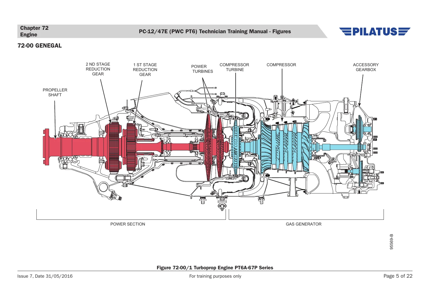
Figure 72-00/1 Turboprop Engine PT6A-67P Series
Figure 72-00/2 External Components – RH Sidep. 111
Figure 72-00/3 External Components – LH Side
Figure 72-00/4 Major Assemblies & Flanges – Gas Generator Section
Figure 72-00/5 Major Assemblies & Flanges – Power Section
Figure 72-00/6 Engine Stations
Figure 72-00/7 Main Engine Bearings – Location
+72-11 REDUCTION GEARBOX
Figure 72-11/1 Reduction Gearbox
Figure 72-11/2 Torque System
+72-20 AIR INLET SECTION
Figure 72-20/1 Compressor Air Inlet
+72-30 COMPRESSOR SECTION
Figure 72-30/1 Compressor Rotor & No. 1 Bearing Area
+72-40 COMBUSTION SECTION
Figure 72-40/1 Combustion Chamber – Layout
+72-50 TURBINE SECTION
Figure 72-50/1 Compressor Turbine Vane Assembly
Figure 72-50/2 Compressor Turbine
Figure 72-50/3 Inter Turbine Stage and T5 Probesp. 112
Figure 72-50/4 Power Turbines
+72-60 ACCESSORY GEARBOX
Figure 72-60/1 Accessory Gearbox – Layout
Figure 72-60/2 Accessory Gearbox Breather
+Chapter 73 Engine Fuel and Control
+73-00 GENERAL
Figure 73-00/1 Engine Fuel – Main Components
+73-10 ENGINE FUEL
Figure 73-10/1 Engine Fuel System – Layout
Figure 73-10/2 Torque Limiter – Location
Figure 73-10/3 Fuel Heater
Figure 73-10/4 High Pressure Fuel Pump
Figure 73-10/5 Fuel Flow Divider and Purge Valve
Figure 73-10/6 Fuel Nozzle
Figure 73-10/7 Torque Limiterp. 115
+73-20 FUEL CONTROL
Figure 73-20/1 Fuel Control Unit – Components
Figure 73-20/2 Fuel Control Unit – Main Flow
Figure 73-20/3 Fuel Control Unit – Metering Section
Figure 73-20/4 Fuel Control system – Schematic
+Chapter 74 Ignition
+74-00 GENERAL
Figure 74-00/1 Ignition Switch – Location
Figure 74-00/2 Ignition Components – Location
Figure 74-00/3 Fire/Ignition System – Schematic
+Chapter 75 Air
+75-00 GENERAL
Figure 75-00/1 Turbine Cooling and Air Bleed System
Figure 75-00/2 Bearing Compartment Sealing
+75-30 COMPRESSOR BLEED VALVE
Figure 75-30/1 Compressor Bleed Valve – Location and Operation
+Chapter 76 Engine Controlsp. 120
+76-00 GENERAL
Figure 76-00/1 Engine Controls – Cockpit
Figure 76-00/2 Manual Override – Operation
+Chapter 77 Engine Indicating
+77-00 GENERAL
Figure 77-00/1 Engine Torque Transducer – Location
+77-40 INTEGRATED ENGINE INSTRUMENT SYSTEM
Figure 77-40/1 Engine Indication – Schematic
Figure 77-40/2 Torque Indication
Figure 77-40/3 Inter Turbine Temperature Indication
Figure 77-40/4 Gas Generator Speed Indication
+Chapter 78 Exhaust
+78-00 GENERAL
Figure 78-00/1 Exhaust Ducts
+Chapter 79 Oil
+79-00 GENERAL
Figure 79-00/1 Oil System – Bottom View
+79-20 DISTRIBUTION
Figure 79-20/1 Oil System (Front)
Figure 79-20/2 Oil System (Rear)
Figure 79-20/3 Oil Pressure Regulating and Filtration
Figure 79-20/4 Thermostatic Bypass and Check Valve
Figure 79-20/5 Oil Tank Pressurizing Valve
+79-30 INDICATING
Figure 79-30/1 Oil Pressure Switch, Oil Pressure Transducer and Oil Temperature Sensor – Location
Figure 79-30/2 Chip Detector – Location
Figure 79-30/3 Oil Indication – Schematic
Figure 79-30/4 Oil Indication – PFD Engine Windowp. 124
+Chapter 80 Starting
+80-00 GENERALp. 125
Figure 80-00/1 Starting – Controls and Indicationp. 125
+80-10 CRANKING
Figure 80-10/1 Starting – Schematic
PT6A-67P Powerplant Coverage
The powerplant section identifies the PC-12/47E engine as the Pratt & Whitney Canada PT6A-67P. Engine training figures show the free-turbine layout, external components, major assemblies and flanges, engine stations, main bearings and the reduction gearbox. Separate sections address the air inlet, compressor, combustion chamber, compressor turbine, power turbines and accessory gearbox. Additional chapters continue into engine fuel and control, ignition, air, engine controls, engine indicating, exhaust, oil and starting.
The notes explain how the gas-generator and power-turbine sections relate to the propeller shaft, how air moves through the compressor and combustion areas, and how engine indications and related systems fit into the broader aircraft architecture. This makes the Pilatus PC-12/47E PWC PT6 Technician Training Manual particularly useful for learners who want both aircraft-level and powerplant-level context in one publication.
Develop PC-12/47E Technical Familiarity Before the Job
Use the Pilatus PC-12/47E PWC PT6 Technician Training Manual Figures & Notes – Issue 7 (2016) to study system operation, component locations, servicing concepts, cockpit indications, safety precautions and the technical relationships that sit behind maintenance tasks and fault investigation. Understanding those relationships helps a technician approach current approved procedures and specifications with better context and reduces the risk of treating a component in isolation. Because this manual is training material, actual maintenance and repair must be performed using the applicable current maintenance documentation rather than this publication.
After payment, the manual is delivered as an instant PDF download with no physical shipping. The file can be opened on compatible computers, tablets and phones, and pages can be printed when a paper reference is useful for study or classroom use.


Reviews
There are no reviews yet.