
Airbus A380-800 Aircraft Characteristics Airport and Maintenance Planning Manual – AC Revision 17
Original price was: $39.95.$24.95Current price is: $24.95.
Airbus A380-800 Aircraft Characteristics – Airport and Maintenance Planning (AC) manual, Revision 17 dated Nov 01/20. Full ground maneuvering, terminal servicing, engine danger areas, jacking, pavement data and ACN/PCN plus ACR/PCR coverage for every A380-800 weight variant and both the Engine Alliance GP7200 and Rolls-Royce Trent 900 powerplants.
Description
Airbus A380-800 Aircraft Characteristics – Airport and Maintenance Planning Manual
This is the complete Airbus A380-800 Aircraft Characteristics – Airport and Maintenance Planning (AC) manual at Revision No. 17, dated Nov 01/20. It is the reference document issued for the A380 series aircraft to give airport operators, airlines and Maintenance/Repair Organizations the data needed to plan airport infrastructure and maintenance facilities around the aircraft. Everything in it is written around the physical aircraft itself – its dimensions, clearances, turning geometry, servicing points, engine efflux, jacking loads and pavement behaviour – rather than around line maintenance tasks.
File Details
- Manual type: Aircraft Characteristics – Airport and Maintenance Planning (AC)
- Brand / manufacturer: Airbus
- Model covered: A380-800
- Document revision: Revision No. 17
- Revision date: Nov 01/20
- Language: English
- Page count: 311 pages
- File format: PDF
Chapters Covered
- 1 – Scope: Introduction, Glossary
- 2 – Aircraft Description: General Aircraft Characteristics Data, General Aircraft Dimensions, Ground Clearances, Interior Arrangement – Plan View, Interior Arrangements – Cross Section, Cargo Compartments, Door Clearances, Escape Slides, Landing Gear, Landing Gear Maintenance Pits, Exterior Lighting, Antennas and Probes Location, Power Plant, Leveling Symmetry and Alignment, Jacking for Maintenance
- 3 – Aircraft Performance: General Information, Payload/Range ISA Conditions, Take-Off Weight Limitation ISA Conditions, Take-Off Weight Limitation ISA + 15 C Conditions, Aerodrome Reference Code, Landing Field Length, Final Approach Speed
- 4 – Ground Maneuvering: General Information, Turning Radii, Minimum Turning Radii, Visibility from Cockpit in Static Position, Runway and Taxiway Turn Paths, Runway Holding Bay (Apron), Minimum Line-Up Distance Corrections, Aircraft Mooring
- 5 – Terminal Servicing: Aircraft Servicing Arrangements, Typical Ramp Layout (Open Apron), Typical Ramp Layout (Gate), Typical Turn-Round Time via Main and Upper Deck, Typical Turn-Round Time via Main Deck, Ground Service Connections Layout, Grounding (Earthing) Points, Hydraulic, Electrical, Oxygen, Fuel, Pneumatic, Oil, Potable Water and Waste Water servicing, Cargo Control Panels, Engine Starting Pneumatic Requirements, Ground Pneumatic Power Requirements, Preconditioned Airflow Requirements, Ground Towing Requirements, De-Icing and External Cleaning
- 6 – Operating Conditions: Engine Exhaust Velocities and Temperatures, Danger Areas of the Engines, APU Exhaust Velocities and Temperatures
- 7 – Pavement Data: General Information, Landing Gear Footprint, Maximum Pavement Loads, Landing Gear Loading on Pavement, Flexible Pavement Requirements, Rigid Pavement Requirements, ACN/PCN Reporting System, ACR/PCR Reporting System
- 8 – Scaled Drawings
- 10 – Aircraft Rescue and Fire Fighting
What This A380 Airport and Maintenance Planning Manual Gives You
The A380-800 is a subsonic, very long range, very high capacity civil transport, offered with two engine types – the Engine Alliance GP7200 series and the Rolls-Royce Trent 900 series. This AC manual is built to describe that aircraft to the people who have to fit it into an airport: the planners drawing taxiway fillets, the engineers designing stands and pits, and the MRO teams working out how to lift and service an aircraft of this size.
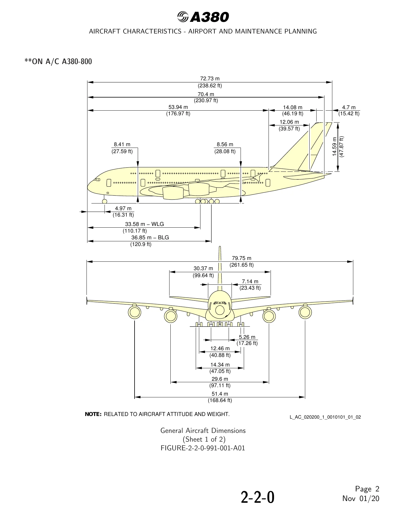
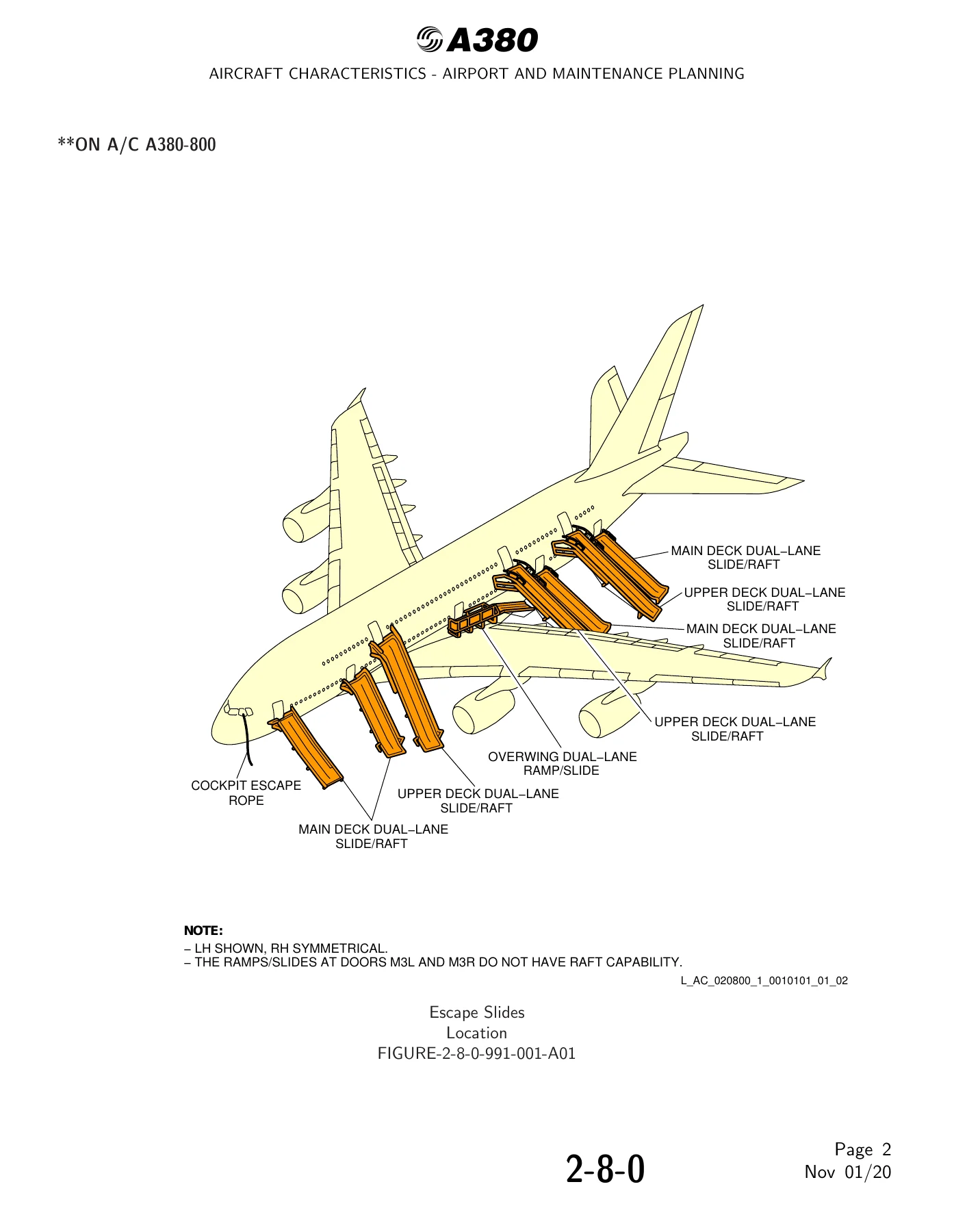
Section 2 opens with the general aircraft characteristics data for every weight variant, then moves into the dimensional drawings – overall length and height, wheelbase measured to the Wing Landing Gear and to the Body Landing Gear, track, and the wing span figures. Ground clearances are given for a range of configurations including leading edge slats extended, trailing edge flaps extended, spoilers extended, ailerons up and down, flap tracks extended, and the trimmable horizontal stabilizer and elevators down. Door clearances are broken out by door group: forward passenger doors, main and upper deck passenger doors, aft passenger doors, forward and aft cargo compartment doors, forward nose landing gear doors, wing landing gear main doors, body landing gear outer and inner doors, and the APU door. Escape slide locations and dimensions are given for the upper deck, the main deck and the overwing ramp/slides.
The landing gear chapter covers the two Wing Landing Gears with their four-wheel bogies, the two Body Landing Gears with six-wheel bogies, and the twin-wheel Nose Landing Gear, including servicing points, charging valves, seal changeover valves, ground lock safety devices, tow truck power connector and the landing gear maintenance pit envelopes with the necessary pit depths for the WLG and BLG.
Ground maneuvering data is unusually detailed and is one of the reasons this document is worth having on hand. It includes turning radii and minimum turning radii tables giving R3 NLG, R4 WING, R5 NOSE and R6 THS values against steering angle for Type 1 and Type 2 turns, the visibility from the cockpit in static position, and the full set of runway and taxiway turn path drawings – 135 and 90 degree turns from runway to taxiway, 180 degree turns on a runway, 135 and 90 degree turns from taxiway to taxiway – each presented with both the judgemental oversteer method and the cockpit tracks centerline method. Minimum line-up distance corrections are tabulated for 90 degree turns on runway entry, 180 degree turns on a runway turn pad, and 180 degree turns on runway width, for both 45 m and 60 m runway widths.
Terminal servicing covers ramp layouts for open apron and gate stands, plus turn-round time charts for servicing via the main and upper deck and via the main deck only. Every ground service connection is located with its access door number, distance aft of the nose, distance from the aircraft centerline and mean height from the ground – hydraulic reservoir servicing panel and hydraulic ground connectors, external power receptacles and the tow truck power connector with its pin allocation, oxygen filling points, refuel/defuel control panel and pressure refuel connectors with overpressure protector and NACA flame arrestor locations, low pressure and high pressure pneumatic connectors, engine oil, VFG oil, starter oil and APU oil servicing for both the Trent 900 and the GP7200, potable water, waste water and the forward and aft cargo control panels.
Operating conditions in Section 6 give engine exhaust velocities and temperatures at ground idle, breakaway and maximum take-off power for both engine types, plus the danger areas of the engines at each of those power settings with the intake suction danger area radius and the exhaust danger area length. APU exhaust velocities and temperatures are also charted for maximum ECS conditions and for MES conditions.
Section 7 is the pavement planning material: landing gear footprint, maximum pavement loads per strut under braking and static conditions, and the reporting systems. ACN data is tabulated for both rigid pavement subgrades (high, medium, low, ultra-low) and flexible pavement subgrades (CBR 15, 10, 6 and 3) at maximum ramp weight and at 300 000 kg for every weight variant, and the newer Aircraft Classification Rating table is provided alongside it.
Weight Variants and Engines Covered
The characteristics tables in this manual are specific to each A380-800 weight variant, from WV000 through WV014. The maximum ramp weight, maximum taxi weight, maximum take-off weight, maximum landing weight and maximum zero fuel weight are given for each variant, with imperial equivalents. Both powerplant options are addressed throughout – the Engine Alliance GP7200 series and the Rolls-Royce Trent 900 series – with engine dimensions, nacelle dimensions, fan cowl handling, thrust reverser cowl and fan exhaust cowl handling data given separately for each engine. The document also records the aircraft’s final approach speed of 138 kt at a maximum landing weight of 395 000 kg, which classifies the A380 into Aircraft Approach Category C, and confirms that the A380 can operate on aerodromes classified as code 4F under the ICAO Aerodrome Reference Code, and on code 4E aerodromes provided specific conditions are met.
Who This Manual Is For
Airport planners sizing taxiways, aprons and runway turn pads for the A380 will find the turning path geometry, minimum line-up distance corrections and pavement load data they need. Ground handling and ramp teams get the stand layouts, service connection locations and turn-round time baselines. Maintenance and MRO organizations get the jacking points with their maximum eligible loads, the jacking heights for landing gear extension and removal, the landing gear jacking point heights for wheel and brake changes on the NLG, WLG and BLG, and the maintenance pit envelopes. Rescue and fire fighting personnel get the last chapter, covering highly flammable and hazardous materials, battery locations and access, crew rest compartments, wheel and brake overheat safety areas, composite materials location, ground lock safety devices, emergency evacuation devices, passenger and cargo doors, control panels, APU compartment access, aircraft ground clearances and structural break-in points.
IMAGES PREVIEW
Instant PDF Delivery
This Airbus A380-800 Aircraft Characteristics Airport and Maintenance Planning manual is delivered as an instant PDF download – no shipping, no waiting. Open it on a laptop, tablet or phone in the office, on the ramp or in the hangar, and print whichever drawings, clearance tables or servicing sheets you need for the job in front of you. With the dimensional drawings, turn path geometry, service connection coordinates, jacking loads and pavement ratings all in one document, this AC manual gives you the correct figures to plan, position and support the A380-800 without working from second-hand numbers.

Reviews
There are no reviews yet.