
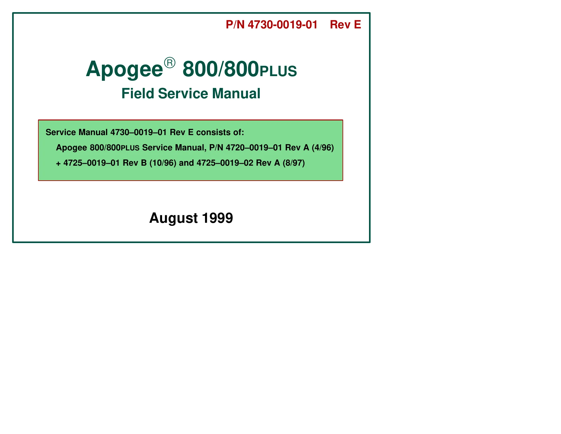

ATL Apogee 800 800PLUS Ultrasound Field Service Manual 4730-0019-01 Rev E
Original price was: $49.95.$29.95Current price is: $29.95.
Field service reference for ATL Apogee 800 and Apogee 800PLUS ultrasound systems covering system theory, installation, performance testing, adjustments, cabling, preventive maintenance, troubleshooting, disassembly, software changes, specifications, configuration data, PCB reference information, and field-replaceable parts.
Description
The ATL Apogee 800 800PLUS Ultrasound Field Service Manual 4730-0019-01 Rev E is a detailed technical service reference for the Apogee 800 and Apogee 800PLUS ultrasound systems. It addresses the v1.2, v1.9x, and v3.x system families and is structured around the work required to understand system architecture, install and verify equipment, perform performance checks and alignments, diagnose faults, service electronic assemblies, identify cabling and parts, and maintain hardware/software compatibility. The manual combines functional theory with service procedures, diagnostic information, specifications, interconnection drawings, PCB references, mechanical illustrations, and parts data.
System Architecture and Service Scope
The manual begins by identifying the major differences between Apogee 800 system versions. It explains changes to the keyboard, system processor, floppy-disk interface, PCBs, front-end electronics, cart construction, EMC shielding, cooling, scanhead switching, and other features associated with the v1.9x Advanced Performance Upgrade and v3.x Apogee 800PLUS systems. Operating modes documented include 2D/B-mode, M-mode, color flow, Color M-mode, pulsed-wave Doppler, continuous-wave Doppler, High PRF Doppler, and Color Power Angio where applicable.
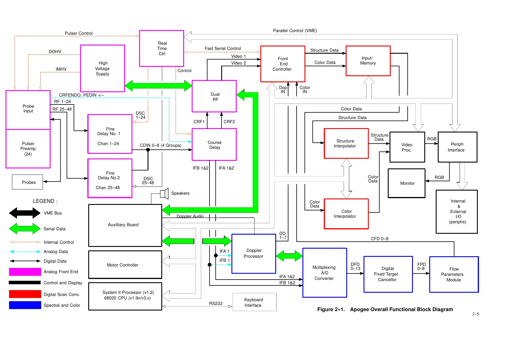
The theory section traces system operation through the control subsystem, Electronic Front End, Doppler Spectrum Analyzer, Color Flow Module, Digital Scan Converter, and display subsystem. Individual coverage is provided for the SYS/CPU, Auxiliary, Motor Controller, Real-Time Control, High Voltage, Probe Input, Probe Select, Pulser/Preamp, Fine Delay, Coarse Delay, Dual RF, Doppler Processor, Multiplexing A/D Converter, Digital Fixed Target Cancellor, Flow Parameters Module, Front End Controller, Input/Memory, Image/Memory, Structure and Color Interpolators, Video Processor, and Peripheral Interface PCBs. Signal-flow explanations cover tissue imaging, spectral Doppler, color flow, ECG, video, and audio paths.
Performance Testing and Alignment
A major part of the ATL Apogee 800 800PLUS Ultrasound Field Service Manual 4730-0019-01 Rev E is devoted to confirming correct operation after installation, upgrade, preventive maintenance, or repair. The performance-test procedures include power-supply voltage checks, initialization, user-interface tests, image-quality evaluation, save/recall functions, M-mode and Doppler quality checks, color Doppler testing, video-monitor checks, external and internal I/O verification, ECG functions, printers, VCR operation, and safety testing.
The adjustment section documents service alignment work for the front end, Dual RF and FEC PCBs, Video Processor PCB, Doppler Processor baseline noise, and monitor systems. It includes test-point locations, required equipment, setup conditions, reference voltages, tolerances, test patterns, and monitor geometry procedures. The manual specifically notes situations in which adjustment is not recommended, such as a DC power supply that fails specified voltage tolerances and should instead be replaced.
Troubleshooting and Diagnostic Tools
The troubleshooting material provides a structured fault-isolation process based on observed symptoms, functional checks, service software, theory of operation, and previously encountered failures. Symptom/action tables cover conditions such as failure to power on, no monitor display, initialization errors, scanhead identification problems, keyboard communication faults, missing ultrasound data, degraded Doppler performance, color-path failures, and RGB display problems.
For v1.2 systems, the manual lists service error messages covering processor, keyboard, Auxiliary PCB, interpolator, memory, Front End Controller, Motor Controller, serial paths, board versions, and other system conditions. The service-software section explains use of diagnostic test patterns and utilities for B-mode, M-mode, color, video, the Color Flow Module, board revision information, and front-end testing. Hardware/software configuration is treated as part of fault diagnosis because PCB revision, Board ID, and Hardware Configuration Number compatibility can affect system operation.
Cabling, Configuration, and Parts Identification
System interconnect information is presented with diagrams for the v1.2/v1.9x and v3.x configurations. These drawings identify links among the monitor, keyboard, speakers, Internal and External I/O assemblies, card cage, probe/front-end assembly, Motor Controller, disk drive, AC/ISO enclosure, DC power supply, fans, ECG connections, peripherals, ISEM, and AAM. Additional drawings document connector panels, backplanes, cable assemblies, wire lists, power connections, keyboard wiring, speaker and headphone cabling, and printer interfaces.
Configuration material covers system software replacement levels, PCB identification, compatibility, Board ID and Hardware Configuration Number information, component-reference drawings, and scanhead configuration. The parts section provides recommended field-replaceable parts for Apogee 800 v1.2, v1.9x, and v3.x systems and uses illustrations and keyed tables to locate assemblies, subassemblies, and components by part number and description.
System Specifications and Scanhead Data
The specifications section records system dimensions, weight, environmental requirements, power requirements, video characteristics, scanhead specifications, applications, and standards information. The Apogee system is listed at 145.11 cm / 57.13 in high with the monitor, 111.40 cm / 43.86 in without the monitor, 68.58 cm / 27 in wide, and 86.36 cm / 34 in deep, with a weight of 141 kg / 310 lbs without peripherals. Operating temperature is given as 16-35 degrees C / 61-90 degrees F, with operating humidity of 30-75% RH non-condensing and heat output of 2300 BTU/Hr (670 W). Power data covers 120 VAC and 230 VAC operation at 45-65 Hz. The scanhead tables include probe type, dimensions, imaging depth, Doppler frequencies, color frequencies, and applicable clinical applications for supported configurations.
File Details
- Manual type: Field Service Manual
- Brand: ATL Ultrasound
- Models: Apogee 800 / 800PLUS
- System versions covered: v1.2, v1.9x, v3.x
- Document number: 4730-0019-01 Rev E
- Date: August 1999
- Language: English
- Pages: 686
- Format: PDF
Chapters Covered
- 1 General Information
- System overview, applications, operating modes, display formats, image/data memories, controls, calculations, supported scanheads, system components and peripherals
- 2 Theory of Operation
- Operating modes, bus structure, control subsystem, Electronic Front End, Doppler Spectrum Analyzer, Color Flow Module, Digital Scan Converter, display subsystem, probe theory, power distribution and signal-flow paths
- 3 Safety
- Electrical safety, mechanical safety, equipment protection and symbol definitions
- 4 Installation/De-Installation
- Uncrating, monitor installation, system installation, OEM peripheral installation, printer/camera/VCR connections, ISEM/AAM information and crating procedures
- 5 Performance Tests
- DC power checks, initialization, user-interface testing, 2D image quality, save/recall, M-mode, PW/CW/HPRF and color Doppler testing, monitor, I/O, ECG, printer, VCR and safety checks
- 6 Adjustments
- Front-end alignment, RF/FEC adjustment, Video Processor alignment, Doppler Processor baseline noise, 14-inch monitor alignment and Apogee 800PLUS Electrohome monitor adjustments
- 7 Cabling
- System interconnection diagrams, connector assemblies and cable assemblies
- 8 Preventive Maintenance
- Cleaning, inspection, verification, alignment/calibration and functional testing
- 9 Troubleshooting
- Functional checks, fault isolation, error messages, previously encountered failures, service software diagnostics, test patterns and board-information tools
- 10 Disassembly
- General disassembly procedures and mechanical reference illustrations for Apogee 800 and Apogee 800PLUS systems
- 11 Software Change History
- Software releases, feature additions, performance improvements, supported features and upgrade differences
- 12 Specifications
- Dimensions, weight, environmental requirements, power, video and scanhead specifications, applications and standards compliance
- 13 Configuration
- Software compatibility, PCB reference data, Board ID/HCN information, software part numbers, PCB identification and scanhead configuration
- 14 Parts
- Recommended field-replaceable parts, ordering information, keyed illustrations, assembly breakdowns, part numbers and descriptions
Together these sections give trained service personnel a connected reference from system architecture and signal flow through verification, alignment, diagnosis, mechanical access, configuration control, specifications, and replacement-part identification. This is particularly useful where troubleshooting requires moving between a symptom, an electronic subsystem, a test procedure, an interconnection drawing, and the applicable PCB or component reference.
Service Reference for Apogee 800 and 800PLUS
The ATL Apogee 800 800PLUS Ultrasound Field Service Manual 4730-0019-01 Rev E supports practical service work including installation verification, preventive maintenance, image and Doppler performance checks, power-supply testing, PCB and signal-path diagnosis, front-end and video alignment, monitor adjustment, peripheral connection, fault isolation, disassembly, configuration checking, cable tracing, and parts identification. Procedures include measured values, test points, diagnostic menus, diagrams, system-specific cautions, and performance criteria that help technicians work against the documented service requirements rather than relying on general assumptions.
IMAGES PREVIEW
Supplied as an instant PDF download after payment, there is no physical shipping required. The manual can be viewed on compatible phones, tablets, laptops, or desktop computers and pages can be printed when a workshop reference copy is useful.

Reviews
There are no reviews yet.