
Bell B35B 6×6 ADT Parts Manual – December 1996 Illustrated Parts Catalog PDF (P/N 870166)
Original price was: $34.95.$20.95Current price is: $20.95.
Illustrated parts catalog for the Bell B35B 6×6 ADT articulated dump truck, issued December 1996 under document part number 870166. 339 pages covering engine, power train, hydraulic, pneumatic and electrical systems, frame, body, cab and decals with exploded views and matching parts lists.
Description
The Bell B35B 6×6 ADT Parts Manual is the illustrated parts catalog published by Bell Equipment Company for the B35B six-wheel-drive articulated dump truck. Issued in December 1996 under document part number 870166, this 339-page PDF walks the complete machine in five sections, from the engine and power train through the hydraulic, pneumatic and electrical systems to the frame, body, cab and decal set. Every assembly is presented as an illustrated breakdown supported by a matching parts list, exactly as Bell’s Technical Documentation Department produced it.
File Details
- Manual type: Illustrated Parts Manual (Parts Catalog)
- Brand / manufacturer: Bell Equipment Company, Richards Bay
- Model: B35B 6X6 ADT (Articulated Dump Truck)
- Document part number: 870166
- Issue: December 1996
- Language: English
- Page count: 339 pages
- File format: PDF
Chapters Covered
- Section 1 – General Information: Bulletins, List of Abbreviations, Ordering of Parts, General Dimensions, Machine Labels and Identification Plates, Service Kits – B35B
- Section 2 – Engine: Engine and Miscellaneous Parts, Air Cleaner Assembly, Exhaust Assembly, Fuel System, Stop Cable Assembly, Throttle Assembly, Accelerator Foot Valve, Pneumatic Modulator, Air Throttle Control, Engine Cooling System
- Section 3 – Power Train: Transmission and Miscellaneous Parts, Oil Cooler Assembly, Transfer Case and Miscellaneous Parts, Transfer Case (Housing, Front Housing, Rear Housing, Drive Shaft, Double Gear, Output Shaft, Flange, Gear Shifting, Differential Shifting Lock), Propshaft Layout, Propshafts, Driveline, Mechanical C Clamp Brake Assembly, Front Axle Miscellaneous Parts, Suspension Strut, Front Axle Assembly STD, Rear Suspension, Middle Axle Assembly STD (4.11:1), Rear Axle Assembly STD (4.11:1), Front Differential, Thru Drive 4.11:1, Rear Differential (4.11:1), Brake System, Brake Caliper Assembly, Wheel Assembly
- Section 4 – Systems: 4A Hydraulic System (with and without emergency steering, Control Valve, Hydraulic Pump, Hydraulic Tank, Hydraulic Filter Assembly, Flow Amplifier, Priority Valve, Steering Valve, Steering Cylinder, Cab Tilt Cylinder, Lift Cylinder)
- Section 4B – Pneumatic System: Front Pneumatic System, Cab Pneumatic Circuit, Rear Pneumatic Circuit, Push Button Valve, Park Brake Spring Actuator, Air / Hydraulic Brake Actuator, Relay Emergency Valve, Solenoid Valve, Pressure Protection Valve, Unloader Valve with Integral Air Drier Assembly, Park Brake Valve, Brake Valve, Control Valve
- Section 4C – Electrical System: Schematic symbols for lights, manual switches, pressure and temperature switches / senders, gauges, electronic devices, solenoid controlled devices, general wiring, battery and electric motors; Starting Charging Circuit, Gauges and Warning Light Circuit, Aircon and Wiper Circuit, Reverse and Stop Light EVB Circuit, Lighting Circuit, Turn Indicators and Hazard, Low Range / High Range Selector Circuit, Connectors 1–8, Instrument Panels, Indicator Switch, Circuit Breaker Board, Battery, Clamps and Cables, Windscreen Wiper and Washer, Headlight, Rear Lights, Indicator and Siren
- Section 5 – Frame and Body: Bonnet Assembly, Bonnet Latch Assembly, Cab Exterior Fittings, Cab Interior Fittings, Airconditioner and Heater System, Door Handle Assembly, Seat Assembly, Steering Column, Front Frame and Body, Rear Frame and Bin, Articulation and Oscillation Assembly, Steering Cylinder Mountings, Tip Cylinder Mountings, Bin Heater Assembly, Articulation Joint Bearing Assembly, Cab Tilt Assembly, Decals
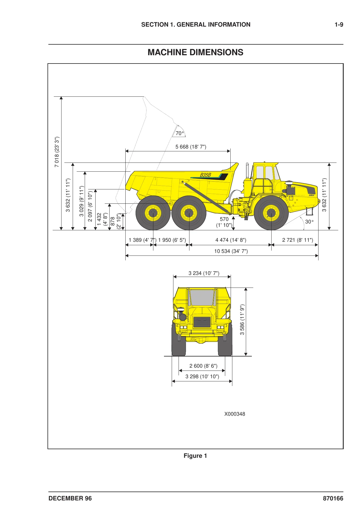
What makes this Bell B35B 6×6 ADT parts catalog genuinely useful is that nothing is left as a bare number. Each of the assemblies above is drawn as an exploded illustration with ballooned item numbers, and the facing page carries the corresponding list of item numbers, part numbers, quantities, descriptions and remarks. That structure is repeated from the smallest clip and washer in the cab interior fittings right through to the ring gear and pinion set in the rear differential. The opening General Information section adds the practical layer around the parts data — a full abbreviation key covering terms such as ADE, ATDC, BTDC, CTD, FMC, SMC, SAE, SMR and ZF, an eight-point checklist of the information Bell requires when you order, and the machine’s key overall dimensions so you can confirm you are looking at the right truck before you spend money on the wrong component.
How the Illustrated Breakdowns Are Organised
Each section opens with an illustrated reference page that keys the major assemblies to their page numbers, so you can move from a general view of the machine straight to the correct breakdown. The engine section, for example, begins with a full machine illustration keyed to Engine and Miscellaneous Parts, Air Cleaner Assembly, Exhaust Assembly, Fuel System, Stop Cable Assembly, Throttle Assembly, Accelerator Foot Valve, Pneumatic Modulator, Air Throttle Control and Engine Cooling System. The power train section follows the same logic across twenty-three listed assemblies, and the Frame and Body section repeats it across sixteen, ending with the complete decal schedule.
The transfer case is broken down further into its own internal sub-assemblies — housing, front housing, rear housing, drive shaft, double gear, output shaft, flange, gear shifting and differential shifting lock — so that internal components can be identified individually rather than as one sealed unit. Brake hardware appears in several places through the power train section, covering the mechanical C clamp brake assembly and the brake caliper assembly, with separate front and rear brake pipe and caliper callouts in the axle and differential breakdowns.
Service Kits Listed for the B35B
The General Information section includes the factory service kit listings for the B35B at four service intervals, each with its own part number and a full contents list of part numbers, quantities and descriptions:
- 100 SMR service kit – P/N 360877 (including rocker cover gasket, spin-on element, fuel filter, oil filter element and fuel filter element)
- 250/750 SMR service kit – P/N 360878 (including sealing washer, primary air filter, safety air filter, oil filter element and fuel filter element)
- 500 SMR service kit – P/N 360879 (including drive belt, compressor drive belt, rocker cover gasket, fuel spin-on filter, filter element, air filters and Loctite)
- 1000 SMR service kit – P/N 360880 (including drive belts, oil pan plug, pan filter kit, spin-on element, air filters, oil and fuel filter elements and Loctite)
Having the kit part numbers and the individual contents of each kit side by side means a workshop can either order the complete kit for a scheduled service or pull only the specific line items it actually needs.
Systems Coverage Beyond the Mechanical Sections
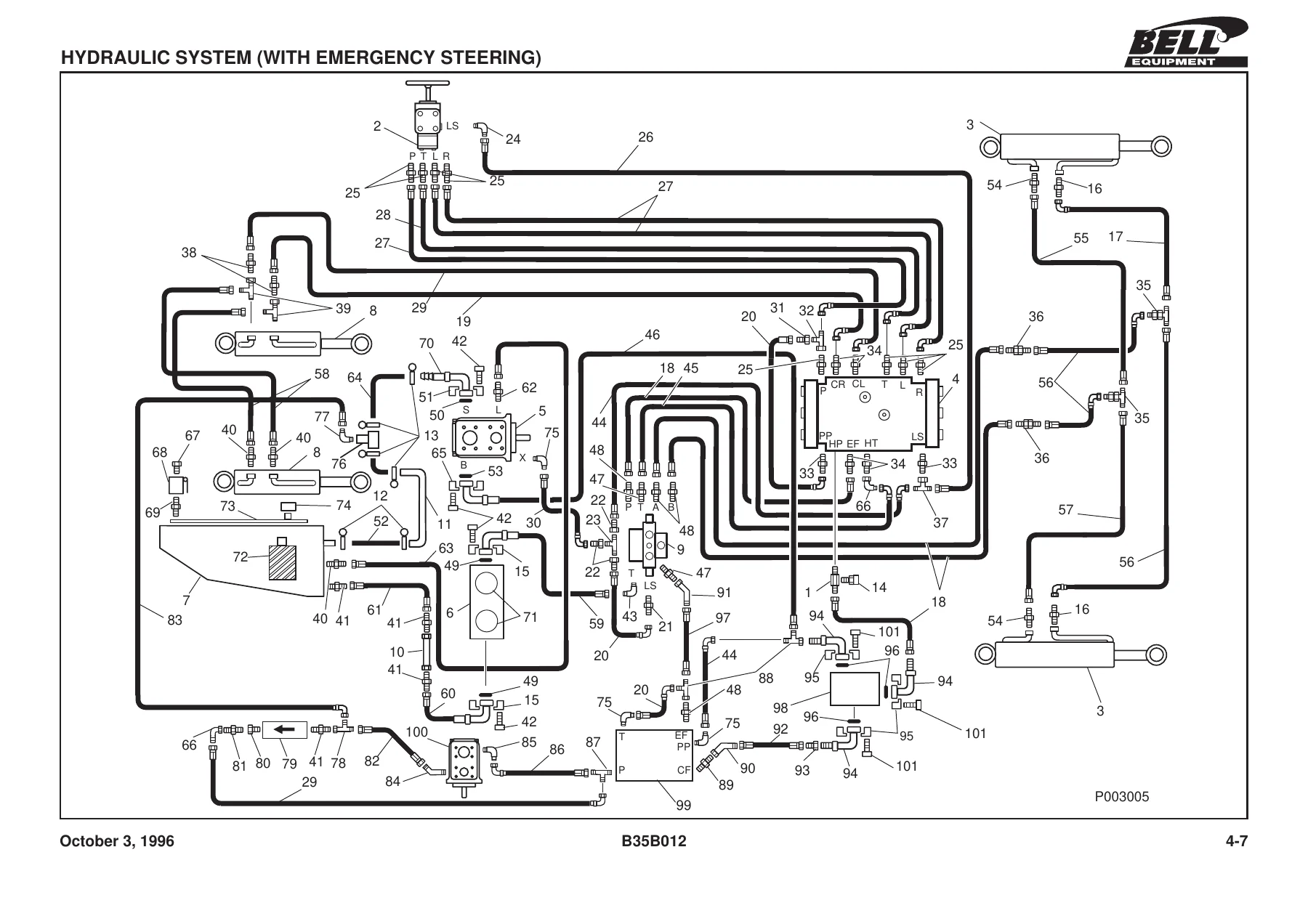
The hydraulic coverage in this Bell B35B 6×6 ADT parts manual is split into two complete system schematics — one with emergency steering and one without — each keyed to the same numbered parts list so every hose assembly, adaptor, elbow, tee piece, bulkhead, flange half, ball valve and cylinder is individually identifiable. The pneumatic side is treated the same way across front, cab and rear circuits, with dedicated breakdowns for the push button valve, park brake spring actuator, air / hydraulic brake actuator, relay emergency valve, solenoid valve, pressure protection valve, unloader valve with integral air drier assembly, park brake valve and brake valve. Repair kit part numbers are listed against several of these valves, with the individual seal, O-ring and spring items they include marked so you know exactly what the kit contains before ordering. The electrical section carries schematic symbols and complete circuits for starting and charging, gauges and warning lights, air conditioning and wiper, reverse and stop lights, lighting, turn indicators and hazard, and low range / high range selection, plus connector pin-out tables, instrument panel layouts, the circuit breaker board, battery cables and the individual lamp assemblies.
Identify the Right Part the First Time
For anyone maintaining or rebuilding a Bell B35B 6×6 articulated dump truck, the hard part is rarely the repair itself — it is ordering the correct component. This catalog solves that by tying every part number to a specific ballooned position on a specific illustration for a specific assembly. Whether you are replacing a failed hydraulic hose, chasing a transmission pressure switch, rebuilding a front or rear differential, renewing the bin heater hardware, sourcing brake caliper repair parts or simply restocking consumables for the next service interval, the illustrated breakdown and its parts list give you the item number, quantity and description you need to raise the order accurately.
Working from the correct Bell parts data also protects the machine. Fitment errors on brake, steering and hydraulic components are expensive and potentially dangerous, and the section-by-section structure lets you confirm the exact configuration — standard or emergency steering, front, middle or rear axle position, left or right hand — before committing to a purchase. With the abbreviation key, the ordering checklist and the service kit contents all in the same document, there is no need to cross-reference several sources to place a single order.
IMAGES PREVIEW
Delivered as an instant PDF download after payment, the Bell B35B 6×6 ADT Parts Manual requires no shipping and no waiting. Open it on a workshop PC, laptop, tablet or phone at the machine, print the specific illustrated pages you need for the job and take them into the workshop, or keep the whole 339-page catalog on file for the life of the truck.

Reviews
There are no reviews yet.