Description
Bell E-Series Articulated Dump Truck Service Manual – Complete Workshop Reference
The Bell E-Series Articulated Dump Truck Service Manual is the full workshop reference for the B18E, B20E, B25E, B30E, 2304E and 2806E haulers built to PIN 2.0. Issued as document BN035357 Rev B in May 2015, this 604-page PDF follows a technician through every major system on the machine – from the Allison 3000PR ORS and 3500P ORS transmissions, through the load-sensing hydraulic system and the pneumatic brake circuits, to the HVAC module and the complete electrical architecture built around the CCU2, OEU2, CDU, SSM and memory module controllers.
This is not a slim owner’s booklet. It is the service-level document used to diagnose faults, set pressures, overhaul assemblies and plan scheduled maintenance on Bell E-Series articulated dump trucks and haulers, and it carries the fault-code tables, pin configurations and pressure specifications that make that work possible.
File Details
- Manual type: Service / workshop manual
- Brand: Bell Equipment
- Series: E-Series articulated dump trucks and haulers (PIN 2.0)
- Document number: BN035357
- Revision: Rev B
- Publication date: May 2015
- Language: English
- Page count: 604
- File format: PDF
Chapters Covered
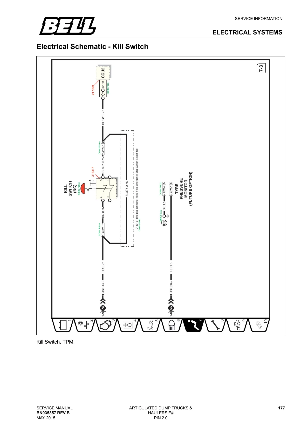
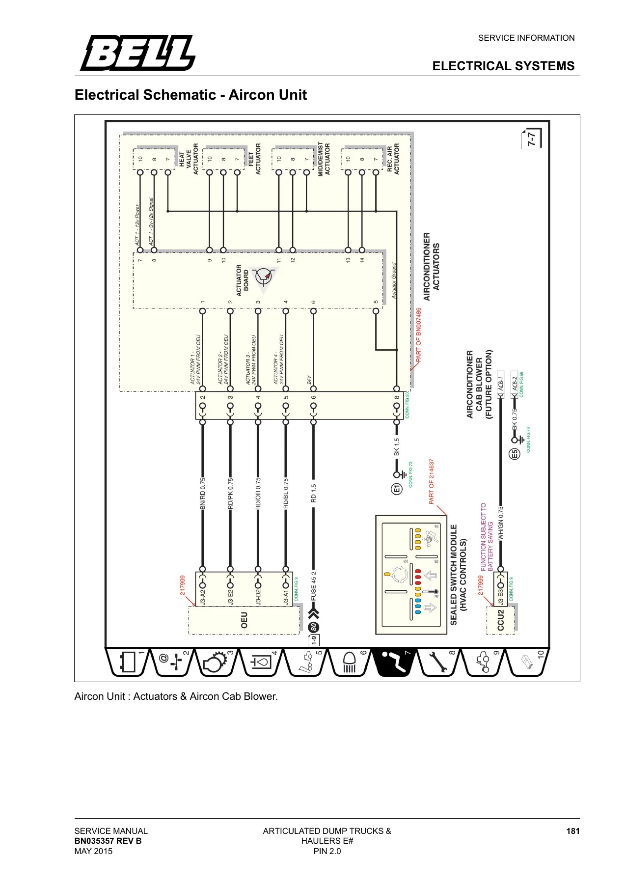
- Electrical Schematics – kill switch and tyre pressure monitor; back-up alarm, electric horn and cab buzzer; electric seat, occupancy and belt switch; wiper motor and washer bottle; aircon actuators and cab blower; aircon blower, temperature, pressure switch and clutch solenoid; radio, speakers and 2-way radio; electric mirrors; bonnet up/down relays and bonnet actuator; diagnostic connector and generic special spare; Igan interface, trailer brake switch and solenoid
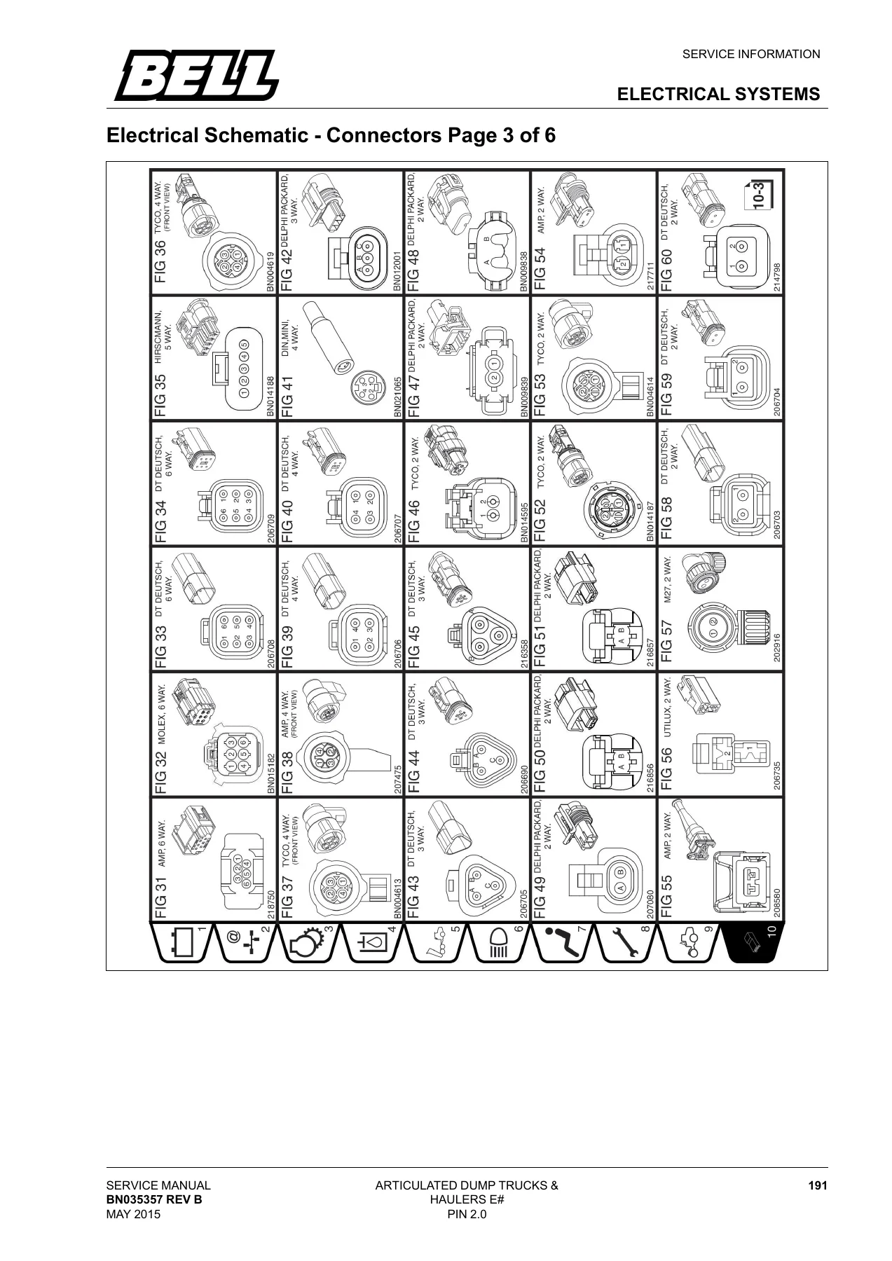
- Connector Identification – six pages of connector figures with mating views and part numbers
- B30E Electrical – ghosting
- Plug Pin Configurations – CCU2 J3, OEU2 J1, OEU2 J2, OEU2 J3, Memory Module 15-pin and 21-pin, and CPC4 connectors 1, 2 and 3 with wire colours, ranges and functions
- CDU and SSM Controls – soft button navigation, toggle device, and the full switch module input/output schedule by function
- Specifications and Tests – pneumatic pressure switches, system air pressure sensor, pneumatic solenoid, hydraulic temperature sensors, bin position sensor, transmission speed sensors, bistable battery switch, fuel level sensor, transmission solenoids
- Bin Angle Sensor calibration and OBW / ASG load cell testing
- Fault Codes and CDU Fault Display – CPC4/ADM3 engine fault codes, ADM3 K-line codes, PLD-MR engine fault codes, ACM fault codes, MCM fault codes, Allison transmission fault codes, analog fault codes, digital input and output fault codes, and the Failure Mode Identifier list
- Transmission – Allison 3000PR ORS, 3000P ORS, 3200P ORS and 3500P ORS general description, cross-sectional diagram, power flow, hydraulic system, clutch application, control module, speed sensors, torque converter, stall testing, planetary gear sets, clutches, autodetect feature, hydraulic circuits by range, retarder, oil level sensor, troubleshooting and clutch pressure tests
- Transfer Case – function, idler assembly, input assembly, output main assembly and line drawings
- Pneumatic System – schematics by model and emission stage, compressor, air drier and unloader valve, pneumatic manifold, exhaust brake and exhaust valve brake circuit, park brake circuit, seat height circuit, inter-axle lock circuit, fault finding, adjustments and tests
- Hydraulic System – theory of operation, schematics, main hydraulic pump, steering valve, secondary steering pump, hydraulic system manifold, service brake system, brake valve, steering and secondary steering operation, bin operation, bin protection, bin versus vehicle speed limit, diagnostic information, pressure tests and pressure settings, auto greaser
- Heating, Ventilation and Air Conditioning – cycle of operation, heater core, fault finding, component location, R134a system test, freeze control switch test, compressor clutch test, high/low pressure switch test, expansion valve test and refrigerant leak test
- General Service Information – service position, service safety, service history and daily walk round checks
- Service and Checks – daily and after every shift, recommended service guide, lubrication specifications, and 500, 1000, 2000 and 4000 hour service and checks
Put together, the Bell E-Series Articulated Dump Truck Service Manual gives a workshop everything it needs to keep a fleet of B18E, B20E, B25E, B30E, 2304E and 2806E machines running to specification. The electrical half of the book is unusually deep – it pairs page-by-page schematics with full connector pin-out tables, so a technician can trace a circuit from the CCU2 or OEU2 plug right through to the component, then cross-reference the symptom against the CDU fault display tables. The mechanical half covers strip-down and rebuild level detail on the Allison transmission, the transfer case, the hydraulic manifold and the pneumatic brake system, with the pressure settings and test procedures written out step by step.
Electrical Schematics and Fault Diagnostics
Every major electrical circuit on the machine is drawn out – kill switch and tyre pressure monitoring, back-up alarm, electric horn and cab buzzer, electric seat occupancy and belt switch, wiper motor and washer bottle, both air conditioning circuits, radio and speakers, electric mirrors, bonnet relays and actuator, diagnostic connector, and the Igan interface with trailer brake switch and solenoid. The connector chapter follows with six pages of illustrated connector figures, so the physical plug can be matched to the schematic before any pin is probed.
The pin configuration tables then decode the main controllers. CCU2 J3 lists every pin with wire colour, range and function – alternator D+, lock up control, bin up and bin down solenoids, CDU wake up signal, seat belt beacon light, fan cut solenoid, brake light, generic special spares, beacon light, mirror heating, relay overspeed, brake charge cut solenoid, aircon cab blower, hydraulic temperature sensor, park brake solenoid, hardware detection, and the ignition and ground pins. OEU2 J1, J2 and J3 are similarly documented, covering headlight bright and dip, aircon fin temperature, input indicator switches, wiper low and high speed, autogreaser pressure and level switches, artic angle sensor, hydraulic high pressure switch, aircon blower, CAN high and low, cab door switch status, cold start light, height sensors, engine air intake pressure switch, hazards and CCU2 wake up, wiper park signal, engine cooling fan, suspension system pressure sensor, washer pump, steering wheel angle sensor, park lights, aircon pressure status and fault, aircon clutch solenoid, aircon evaporator temperature, WDB level sensor, A/C inlet temperature and autogreaser direction solenoid. Memory module plug 15 and 21 pin tables are included, along with CPC4 connector 1, 2 and 3 covering dual speed axle, park brake interlock, throttle signals, ignition and battery supplies, SAE J1939 and powertrain CAN lines, air filter restriction, coolant level, remote throttle, and the extensive output configuration parameters.
Specifications and Service Data
The specifications and tests chapter provides the measurement values needed to confirm a component is good before replacing it – pneumatic pressure switch contact closure points, the system air pressure sensor voltage-to-pressure relationship, solenoid click testing, hydraulic temperature sensor resistance curve, bin position sensor supply and output signal characteristics, transmission speed sensor resistance, and the fuel level sensor resistance curve from full to empty.
Hydraulic pressure settings are listed per model so the main pump, emergency steering pump, steering, brake and pilot pressures can all be set and verified. The pneumatic section covers main system pressure, park brake pressure, park brake adjustment and pad thickness limits, plus wheel brake and park brake test rpm values by machine. Transmission clutch pressure test conditions and specifications are tabulated for neutral, reverse and every forward range, with main pressure, range clutch pressure, lube pressure and lockup pressure given as minimum and maximum values.
Service Schedules and Lubrication
A full recommended service guide breaks the machine down by system – engine, transmission, transfer case, hydraulics, axles, chassis and suspension, cab, pneumatics and electrical, and lubrication – and maps each task to the daily, 500 hour, 1000 hour, 2000 hour or 4000 hour interval. The accompanying lubrication specification tables give the approved oil and coolant standards, viscosity grades and operating ambient temperature windows for engine, transmission, transfer case, hydraulic system, dry disc brake axles, wet disc brake axles and grease. Fluid capacities, filter part references and torque values for drain plugs, filter caps and propshaft bolts are included alongside the procedures.
Complete PDF Bookmark Tree
Complete Bookmarks
The complete bookmarks in the “Bell E-Series Articulated Dump Truck Service Manual – B18E B20E B25E B30E 2304E 2806E” are as follows:
Service Manualp. 3
EC Declaration Of Conformityp. 3
Location Of Operationsp. 5
Bulletinsp. 7
Feedback Formp. 9
+Federal Emissions Warranyp. 11
California Emission Warrantyp. 11
Manufacturer"s Warranty Coveragep. 12
+Owner"s Warranty Rightsp. 12
California Emission Warranty Parts List:p. 13
+Introductionp. 25
+Introductionp. 27
Forewordp. 27
For Your Safetyp. 27
Machine Identificationp. 28
Warrantyp. 28
Disclaimerp. 28
Contact Detailsp. 28
Dealer Stampp. 28
+Safetyp. 29
+Certifications And Standardsp. 31
Safety Specificationp. 31
Unauthorized Machine Modificationsp. 31
+Roll Over And Falling Objects Protective Structure (ROPS/FOPS)p. 31
Unauthorized Modifications Of Machine Cab (ROPS And FOPS)p. 31
Loosening Or Removal Of ROPS And FOPSp. 31
Material Safety Data Sheet (MSDS)p. 31
Noise Emission Levelsp. 32
Safety Regulationsp. 32
+Safety And Operator Conveniencesp. 33
+General Safety Precautionsp. 35
General Safetyp. 35
Operator Qualificationsp. 35
Wear Protective Equipmentp. 35
Stay Clear Of Moving Partsp. 36
Avoid High Pressure Fluidsp. 36
Beware Of Toxic Fumesp. 37
Measures To Prevent Firesp. 37
Clean Trash From Machinep. 37
Prevent Battery Explosions And Acid Burnsp. 38
+Handling Chemical Products And Flammable Fluids Safelyp. 38
Clean Machine Regularlyp. 39
+Health And Safety Information On Lubricants, Fluids And Gasesp. 39
Fluids And Lubricantsp. 40
Dispose Of Waste Properlyp. 41
Prepare For Emergenciesp. 41
+Operating Safety Precautionsp. 43
Mounting And Dismounting Machinep. 43
Start Form Operator Seatp. 43
Use Seat Beltp. 43
Leaving Machinep. 44
Avoid Work Site Hazardsp. 44
Keep Riders Off Machinep. 44
Avoid Reversing Accidentsp. 44
Avoid Machine Tipping Accidentsp. 44
Operating On Slopesp. 45
Travelling On Public Roadsp. 45
Inspect And Maintain ROPSp. 45
+Human Vibrationp. 46
Factors Effecting Drive Exposure to Whole Body Vibrationp. 46
Provisions Aimed at Reducing Exposure to Vibrationsp. 46
Legal Requirementsp. 47
Determination And Assessment of Daily Exposure to Vibrationsp. 47
Vibration Values for Different Construction Vehiclesp. 48
Determination of the Duration of Driver Exposure to Vibrationp. 48
Practical Examplesp. 51
Comfort Ridep. 53
+Maintenance Safety Precautionsp. 55
Prepare For Maintenance And Servicep. 55
Inspect Cooling Systemp. 56
Make Welding Repairsp. 56
Storage For Flexible Hosesp. 56
Replacing Hosesp. 56
Filter And Filter Elementsp. 56
Accumulator Maintenancep. 56
+Safety Signsp. 57
+Tyre Informationp. 79
Tyres And Rimsp. 79
Tyre Pressure – Generalp. 79
Tyre Pressure – Inflation Pressure, Hot vs. Coldp. 79
Recommended Operator Position During Tyre Inflationp. 81
Wheels and Wheel Componentsp. 82
Identify a Damaged Rim or Wheelp. 82
Mounting Of Tyre Onto Wheel Rimp. 83
Fastening of wheel nutsp. 83
Wheel Maintenancep. 83
+Service Informationp. 85
+Operational Checksp. 87
+Operational Checks-Out Procedurep. 87
Ignition Button Pressed Oncep. 87
Ignition Button Pressed (Second Stage), Engine Startp. 88
Engine Stop Button Pressedp. 91
+Enginep. 93
+Engine Descriptionp. 94
Pump Classificationp. 95
Electronic Unit Injector Fuel Systemp. 96
Fuel Deliveryp. 96
Cold Start Operation (Optional for S.A)p. 98
Diagnose Engine Malfunctionsp. 100
+Adjustmentsp. 101
Valve Clearance Adjustmentp. 101
Exhaust Brake Adjustmentp. 102
+Testsp. 103
Cylinder Compression Testp. 103
Fuel Pump Pressure Testp. 104
Oil Pump Pressure Testp. 105
906/ 926 Engine Schematicp. 106
+Engine – OM 936 LAp. 107
Engine Description (B30E Only)p. 107
Engine Datap. 109
+Limp-Home Modep. 111
Failure of drive train CANp. 111
Failure of camshaft position sensorp. 111
Failure of crankshaft position sensorp. 111
Failure of temperature sensorsp. 111
Failure of components of exhaust gas recirculation (EGR)p. 111
Control unit failurep. 111
+Fuel System (Refers to system with DEF filter)p. 112
Low fuel pressurep. 114
High fuel pressurep. 115
The Injectorp. 115
Fuel returnp. 115
+Single-stage turbochargerp. 116
Boost pressure controlp. 116
+Two-stage turbochargerp. 117
Function of two-stage turbochargerp. 118
High-pressure stagep. 119
Low-pressure stagep. 119
+Engine brakep. 119
Functional descriptionp. 119
Principle of decompression brakep. 120
Brake cam contourp. 120
Deactivate engine brakep. 122
Activate engine brakep. 122
+Exhaust gas recirculation on engine OM936p. 122
+Exhaust gas recirculation Overviewp. 123
Exhaust gas recirculation coolerp. 124
+Exhaust gas recirculation controllerp. 124
Recirculation Controller Functionp. 125
Oxygen sensorp. 125
+SCR Systemp. 126
Exhaust Temperature Sensorp. 127
Function of exhaust after-treatment (ACM) control unitp. 127
AdBlue® pump modulep. 127
Heatingp. 128
Metering unit A67p. 128
Reactorp. 129
Adblue Low Level Decalp. 130
+Sensorsp. 130
Crankshaft position sensor B600p. 130
Engine oil level sensor B605p. 131
Fuel temperature sensor B602p. 131
Charge-air temperature sensor B617p. 132
Charge-air pressure and temperature sensor B616p. 132
Rail pressure sensor B622p. 133
Oil pressure switch B604p. 134
Coolant outlet temperature sensor B606p. 134
Compressor housing charge-air temperature sensor B614p. 134
Camshaft position sensor B601p. 135
NOx sensorp. 135
Tank sensorp. 136
Fuel Pressure control valve Y634p. 136
Charge-air pressure actuator Y636p. 137
Flow control valve Y643p. 137
Exhaust recirculation actuator Y621p. 138
Engine brake solenoid Y637p. 138
+Cylinder Headp. 139
Adjusting the valve clearancep. 139
Test Compression Pressurep. 140
Fuel Pressure Measurementp. 144
Engine Management Networkingp. 145
MCM Engine Controllerp. 145
Troubleshooting – Engine Problemsp. 146
+Electrical Systemsp. 149
Can Bus Electrical Schematicp. 150
CAN Circuit Testp. 152
+Controller Area Network (CAN) Diagnosticp. 153
1 System Checkp. 153
2 CAN Termination Resistor Checkp. 153
3 CAN Hi Wire Voltage Checkp. 153
4 CAN Lo Wire Voltage Checkp. 153
5 CAN Hi Wire Voltage Checkp. 153
6 CAN Lo Wire Circuit Checkp. 153
7 Controller Checkp. 154
8 Total resistance checkp. 154
9 Can High shorted to ground testp. 154
Electrical Schematic Symbolsp. 155
Battery And Isolator Switch Electrical Schematicp. 156
Electrical Schematic – Remote Isolator Optionp. 157
Electrical Schematic Start And Charge Circuitp. 158
Electrical Schematic Battery Powerp. 159
Electrical Schematic Battery Powerp. 160
Electrical Schematic Ignition Powerp. 161
Electrical Schematic Ignition Powerp. 162
Electrical Schematicp. 163
Electrical Schematic Ignition Powerp. 164
Electrical Schematic – CCU2 Sensor Power And Sensor Groundp. 165
Electrical Schematic – OEU & XCU Sensor Power & Sensor Groundp. 166
Electrical Schematic Power Circuitp. 167
Electrical Schematic – CAN Circuit Stage 2 & 3Bp. 168
Electrical Schematic – Can Circuit Stage 4p. 169
Electrical Schematic – Memory Modulep. 170
Electrical Schematic Drivelinep. 171
Driveline – Stage 4 Engine – CPC4, ACCP & R2p. 172
Electrical Schematic Drivelinep. 173
Electrical Schematic Drivelinep. 174
Electrical Schematic Drivelinep. 175
Electrical Schematic Drivelinep. 176
Electrical Schematic Drivelinep. 177
Electrical Schematic – Transmissionp. 178
Electrical Schematic – SCR System Stage 3Bp. 179
Electrical Schematic – SCR System Stage 4p. 180
Electrical Schematic – Fanp. 181
Electrical Schematic – Hydraulic Systemp. 182
Electrical Schematic – WDBp. 183
Electrical Schematic – WDB Temperaturep. 184
Electrical Schematic – Hydraulic & Pneumaticp. 185
Electrical Schematic – Brake Pressure 1 & 2, Brake Charge Cut & Braketarder Activation.p. 186
Electrical Schematic – Park Brake, EB & EVB Solenoidp. 187
Electrical Schematic – Automatic Greasingp. 188
Electrical Schematic – Brake High Pressure Filterp. 189
Electrical Schematic -Steering Wheelp. 190
Electrical Schematic – Bin Position Sensor, Bin Up And Down Solenoidp. 191
Electrical Schematic – Suspensionp. 192
Electrical Schematic – Strutsp. 193
Electrical Schematic – Suspension Pressurep. 194
Electrical Schematic – Active Strain Gaugep. 195
Electrical Schematic – Headlights Brights And Dipsp. 196
Electrical Schematic – Park And Brake Lightsp. 197
Electrical Schematic – Front, Side And Rear Indicatorsp. 198
Electrical Schematic – Reverse, Artic And Worklightsp. 199
Electrical Schematic – Interior Light And Bin Side Lightsp. 200
Electrical Schematic – Colour Display Unit Circuitp. 201
Electrical Schematic – SSMp. 202
Electrical Schematic – Kill Switchp. 203
Electrical Schematic – Back Up Alarm, Electric Horn And Cab Buzzerp. 204
Electrical Schematic – Electrical Seat, Occupancy And Belt Switchp. 205
Electrical Schematic – Wiper Motor And Washer Bottlep. 206
Electrical Schematic – Aircon Unitp. 207
Electrical Schematic – Aircon Unitp. 208
Electrical Schematic – Radio, Speakers And 2 way Radiop. 209
Electrical Schematic – Electric Mirrorsp. 210
Electrical Schematic – Bonnet Sensor, Bonnet Switch 1 & 2p. 211
Electrical Schematic – Bonnet Up & Down Relays & Bonnet Actuatorp. 212
Electrical Schematic – Diagnostic Connectorp. 213
Electrical Schematic – Iqan Interface, Trailer Brake Switch & Solenoid.p. 214
Electrical Schematic – Connectors Page 1 of 6p. 215
Electrical Schematic – Connectors Page 2 of 6p. 216
Electrical Schematic – Connectors Page 3 of 6p. 217
Electrical Schematic – Connectors Page 4 of 6p. 218
Electrical Schematic – Connectors Page 5 of 6p. 219
Electrical Schematic – Connectors Page 6 of 6p. 220
Earth Connectionsp. 221
Earth Connections – B30E Ghostingp. 222
Fuse and Relay Layoutp. 223
Fuse and Relay Layoutp. 224
Plug Pin Configurationp. 225
CCU2 J1 – Plug Pin Configurationp. 225
CCU2 J2 – Plug Pin Configurationp. 226
CCU2 J3 – Plug Pin Configurationp. 228
OEU2 J1 – Plug Pin Configurationp. 230
OEU2 J2 – Plug Pin Configurationp. 231
OEU2 J3 – Plug Pin Configurationp. 233
Memory Module Plug 15 – Pin Configurationp. 235
Memory Module Plug 21 – Pin Configurationp. 236
CPC4 Connector ST1p. 237
CPC4 Connector ST2p. 240
CPC4 Connector ST3p. 243
CPC4 Connector ST4p. 249
Sealed Display Controller(SDC) Inputs and Outputsp. 255
SSM Inputs and Outputsp. 256
CCU Inputs and Outputsp. 261
OEU Inputs and Outputsp. 265
+Specifications and Testsp. 267
Pneumatic Pressure Switchesp. 267
System Air Pressure Sensor Testp. 267
Pneumatic Pressure Switches Testp. 267
Pneumatic Solenoid Testp. 267
Hydraulic Temperature Sensorsp. 267
Bin Position Sensor Testp. 268
Transmission Speed Sensorsp. 268
Bistable Battery Switchp. 268
Fuel Level Sensorp. 269
Transmission Speed Sensors Testp. 269
Transmission Solenoids Testp. 269
ON/OFF Solenoidsp. 269
PCS Solenoidsp. 269
Bin Angle Sensorp. 270
+OBW Testingp. 270
ASG OBW Systemp. 270
Ensure Correct Gain Factorsp. 270
Zero with Ideal Conditionsp. 270
Confirm Load Cell Sensitivityp. 271
+Fault Codes And CDU Fault Displayp. 273
Engine Fault Codes (CPC4)p. 273
Engine Fault Codes (ADM 3)p. 314
Engine Fault Codes (PLD-MR)p. 323
MCM Fault Codesp. 341
ACM Fault Codesp. 388
+Transmission Fault Codesp. 414
Allison Fault Codesp. 414
Allison Fault Codes Page 2 of 5p. 415
Allison Fault Codes Page 3 of 5p. 416
Allison Fault Codes Page 4 of 5p. 417
Allison Fault Codes Page 5 of 5p. 418
Analog Fault Codep. 419
Digital Input Fault Codep. 420
Digital Input Frequency Fault Codep. 421
Digital Input Intermittent Fault Codesp. 421
Digital Output Fault Codesp. 421
Information message Fault Codep. 423
Failure Mode Identifierp. 424
+Transmissionp. 427
Transmission General Descriptionp. 427
Transmission Cross Sectional Diagramp. 428
Power Flowp. 430
Functional Description Hydraulic Systemp. 431
Main-Pressure Circuitp. 431
Regulator Valvesp. 431
Clutch Applicationp. 432
Hydraulic Operation During Electrical Interruptionp. 432
Latch Valvesp. 432
Control Main Circuitp. 433
Torque Converter Circuitp. 433
Converter- In Pressure Circuitp. 433
Normal Converter-in Pressurep. 433
Excessive Converter-in Pressurep. 433
Lubrication and Coding Circuitsp. 433
Exhaust Circuitp. 434
Exhaust Backfill Circuitp. 434
Clutch and Solenoid Apply Chartp. 435
General Description Allison Gen 4p. 435
Allison Cab Harnessp. 437
Allison Transmission Harnessp. 438
Speed Sensorsp. 439
Control Modulep. 439
Wiring Harnessesp. 440
Allison Gen 4 Internal Wiring Harnessp. 441
Transmission Identificationp. 442
Torque Converterp. 442
Operational Overviewp. 442
Torque Converter Operationp. 442
Stator One-way Clutch Operationp. 443
Vortex Flow (Torque Multiplication)p. 443
Rotary Flow (Fluid Coupling)p. 443
Lock-Up Clutch Operationp. 443
Stall Testingp. 444
+Stall Protectionp. 444
Stall Test Procedurep. 444
Checking of Stall RPMp. 444
Stall Speedsp. 445
Analysing Stall Test Resultsp. 445
Trouble Shooting A Freewheeling Statorp. 446
Troubleshooting A Stuck Statorp. 446
Planetary Gears Setsp. 446
Gen – 4 Transmission Planetary Configurationp. 446
P3 Planetary configurationp. 446
P2 Planetary Configurationp. 446
P1 Planetary Configurationp. 446
Clutchesp. 447
Control Module Solenoid Locationp. 448
+Autodetect Featurep. 448
Function performed by TCUp. 448
Retarderp. 448
Oil Level Sensor (OLS)p. 449
Throttle Sourcep. 449
Engine Coolant Temperaturep. 449
Trans ID (TID)p. 449
Hydraulic Circuitsp. 450
Neutral to Drive Transitionp. 450
1st Range Operationp. 451
1st Range to 2nd Range Transitionp. 451
First to Second (Step 1)p. 452
First to Second (Step 2)p. 452
2nd Range Operationp. 453
2nd Range Lockup Operationp. 454
2nd Range to 3rd Range Transitionp. 454
3rd Range Operationp. 455
3rd – Lockupp. 455
3rd Range to 4th Range Transitionp. 456
4th Range Operationp. 456
4th Range to 5th Range Transitionp. 457
5th Range Operationp. 457
5th – Lockupp. 458
5th Range to 6th Range Transitionp. 458
Fifth to Sixth (Step 1)p. 458
Fifth to Sixth (Step 2)p. 459
6th Range Operationp. 459
6th – Lockupp. 460
Reverse Operationp. 460
Neutral to Reversep. 460
Solenoid Designations and Modulated Main Pressurep. 461
Main Modulation Solenoidp. 462
Diagnostic Pressure Switch (PS1)p. 462
Neutral And Reversep. 463
2nd, 3rd, 4th and 5thp. 463
1stp. 464
6thp. 464
Torque Converter And Lube Pressure Circuitsp. 464
Converter Flow Valve Operationp. 464
Exhaust Backfill Pressurep. 465
Transmission Retarderp. 465
Retarder Circuit Componentsp. 465
+Definitions And Abbreviationsp. 466
Abbreviations Tablep. 467
System Overviewp. 469
Troubleshootingp. 469
TCU Diagnostic Procedurep. 470
Oil Level Sensor (OLS)p. 470
+Identification of Potential Circuit Problemsp. 471
+Check Clutch Pressuresp. 471
Clutch Pressure Test Conditionsp. 473
Main Pressure and Clutch Pressure Specificationsp. 474
+Transfercasep. 479
+Transfer Case Functionp. 479
Transfer Case Idler Assemblyp. 480
Transfer Case Input Assemblyp. 481
Transfer Case Output Main Assemblyp. 483
+Transfercase Line Drawingp. 484
Inter Axle Not Engagedp. 484
Inter Axle Engagedp. 485
+Pneumatic Systemp. 487
Pneumatic Schematic – B18E & B20E Stage 2p. 487
Pneumatic Schematic – B25E & B30E Stage 4p. 488
Pneumatic Schematic – B25E & B30E SCR Stage 3Bp. 489
Pneumatic Schematic – 2304E & 2806E Stage 2p. 490
Compressorp. 491
Air Drier and Unloader Valvep. 491
Drying The Airp. 491
Unloading The Compressorp. 491
Charging The Regeneration Air Reservoirp. 491
Supplying The Pneumatic Manifoldp. 491
Charging The Pneumatic Systemp. 491
Purging The Air Drierp. 492
Pneumatic Manifoldp. 492
Exhaust Brake and Exhaust Valve Brake Circuitp. 493
Park Brake Circuitp. 493
Seat Height Circuitp. 493
Inter-Axle Lock Circuitp. 493
Fault Findingp. 495
+Adjustments and Testsp. 496
Pneumatic System Main Pressure Test and Adjustmentp. 496
Park Brake Pressure Testp. 497
Park Brake Adjustmentp. 498
Brake Testp. 499
Park Brake Pad Thickness Checkp. 500
+Hydraulic Systemp. 501
Theory Of Operationp. 501
Hydraulic System Circuit Symbolsp. 501
Hydraulic Schematic (B20E Homolagation)p. 502
Hydraulic Schematic (B18E, B25E & B30E)p. 503
Hydraulic Schematic (2304E & 2806E)p. 504
Articulated Dump Truck Hydraulic System Operationp. 505
Main Hydraulic Pump Operationp. 507
Main Hydraulic Pump Load Sense Operationp. 508
Residual Pressurep. 508
Working Pressurep. 509
Compensating Pressurep. 509
Steering Valvep. 510
Secondary Steering Pumpp. 512
Hydraulic System Manifold (Top View)p. 513
Hydraulic System Manifold (Front View)p. 514
Hydraulic System Manifold (Right View)p. 515
Hydraulic System Manifold (Left View)p. 516
Manifold Schematicp. 517
General Descriptionp. 518
+Service Brake System Operationp. 518
Charging Systemp. 518
Charged Systemp. 518
Brake Valve Operationp. 519
Brake Valve – Actuatedp. 519
Steering And Secondary Steering System Operationp. 519
+Bin Operationp. 520
+Diagnostic Informationp. 521
Diagnostic Procedurep. 521
+Testsp. 522
+Hydraulic System Depressurising Procedurep. 522
Pressurised Systemsp. 522
+Procedurep. 522
Bin Hoistingp. 522
Suspensionp. 522
Steering Systemp. 522
Cab Tilting Systemp. 522
Brake Charge Systemp. 522
Methods to discharge brake system:p. 522
+Hydraulic Pressure Settingsp. 523
Table Of Figuresp. 523
Tools And Hydraulic Gaugep. 524
+Machine Settingp. 524
Activating Hydraulic Pump modep. 524
+Setting the Emergency Steering Pump Pressuresp. 524
Toolsp. 524
Set the Emergency Steering Pump Residual Pressurep. 524
Set the Emergency Steering Pump Compensating Pressurep. 525
Fault Findingp. 526
Set the Main Pumpp. 526
Set the Steering Pressurep. 527
Set the Brake Circuit Pressuresp. 528
Set the Bin Tip Pilot Pressurep. 528
Bin Lowering Procedure After Engine/Pump Failurep. 529
Set the Rear Brake System Pressure Reducing Valve pressurep. 530
+Auto Greaserp. 532
Principle Of Operationp. 532
+Modes Of Operationp. 532
Normal Modep. 532
Test Line A/Bp. 533
Test Multi-Cyclep. 533
Fill Line A/Bp. 534
+Troubleshootingp. 534
+Troubleshooting Proceduresp. 536
Operation of the Pump and the Directional solenoid valvep. 536
Internal System Leak is Suspectedp. 536
Main Line Filling and De-aerationp. 537
+Heating, Ventilation and Air Conditioningp. 539
Air Conditioning System Cycle Of Operationp. 539
Heater Core Operationp. 540
Fault Findingp. 541
HVAC Component Locationp. 543
+Testsp. 544
+Operational Checksp. 544
Visual Inspection of Componentsp. 544
All Lines and Hosesp. 544
Air Conditioner Compressor Checkp. 544
Condenser Checkp. 544
Heater/Evaporator Core Checkp. 545
Freeze Control Switch Capillary Tube Checkp. 545
Cab Door and Window Seals Checkp. 545
Filter Checkp. 545
+R134A Air Conditioning System Testp. 545
R134a Air Conditioner System Testp. 545
Diagnose malfunction using the following Diagnostic Chart.p. 546
Air Freeze Control Switch Testp. 549
Air Compressor Clutch Testp. 549
Air High/Low Pressure Switch Testp. 549
Air Expansion Valve Testp. 550
Expansion Valve Bench Testp. 551
Refrigerant Leak Testp. 551
+General Service Informationp. 553
Service Positionp. 554
Service Safetyp. 555
Service Historyp. 556
Daily Walk Round Check Before Servicingp. 556
+Service and Checksp. 557
+Daily and After Every Shiftp. 559
+Check Engine Oil and Coolant levelsp. 559
Check Engine Oil Levelp. 559
Check Coolant Levelp. 559
Check for Oil leaksp. 559
Check Transmission For Oil Leaksp. 559
Check Transmission Oil Levelp. 560
Check the Transfer Case Oil levelp. 560
Check Hydraulic Oil Levelp. 561
Check Grease Levelp. 561
Grease Hingesp. 561
Recommended Service Guidep. 563
+Lubrication Specificationsp. 566
+500 Hours Service and Checksp. 569
Change Engine Oil and Filterp. 569
Drain water from the Primary Fuel Filterp. 570
Check Engine Oil Levelp. 570
Check Coolant Levelp. 571
Replace Fuel Tank Breather Filterp. 572
Check Condition of Fan Belts, including Idler and Tensioner Pulley'sp. 572
Change AdBlue / DEF Tank Breather Filter (Where applicable)p. 573
Replace Transmission Breatherp. 573
Replace Transfer Case Breatherp. 573
Change the Hydraulic Tank Breather Filterp. 574
Test the Brake Accumulator functionp. 574
Check Service and Park Brake Pads And Disks for wearp. 575
Check And Adjust Bin Pad Spacingp. 576
Check Suspension Strut Height, Oil Leaks And General Conditionsp. 577
Set Suspension Strut Height (B30E Shown)p. 578
Inspect and clean Axle Breathersp. 580
Check Operator Controls, Buzzers and Instruments.p. 580
Check working lights, Reverse Buzzerp. 580
Check Electrical Connections and Wire Routing for chaffingp. 580
Record And Delete Fault Codes Found on CDU Displayp. 581
Clean or replace Air Conditioner Filterp. 581
Check the Grease level in the Auto Greasing System (Where applicable)p. 581
Change the Auto Greasing Filler Filterp. 581
Inspect And grease Slip Joints And Propshaft Crosses/Rollersp. 581
Grease all remaining greasable Lube Points, including Oscillation Jointp. 581
Check the Tyre Pressurep. 582
+1000 Hours Service and Checksp. 583
Change the Primary Fuel Filter and Water Separator (RACOR)p. 583
Change Engine Secondary Fuel Filterp. 583
Clean and Replace the Fuel "Pre-Filter" Screenp. 584
+Bleeding & Draining the Fuel Systemp. 584
Bleeding the fuel system without a fuel prefilter on the chassis framep. 584
Bleeding the fuel system with a fuel prefilter on the chassis framep. 584
Clean Crankcase Breather Filterp. 585
Check the Coolant Mixturep. 587
Adjust the Valve Clearancep. 587
Replace Fuel Tank Breather Filterp. 587
Change the Power Core Primary Air Filterp. 587
Change AdBlue / DEF Tank Breather Filterp. 588
Change AdBlue / DEF Filterp. 588
Change the Transmission Oil Filterp. 588
Replace Transmission Breatherp. 589
Replace Transfer Case Breatherp. 589
Replace High Pressure Hydraulic Filter Kitp. 590
+Check the Oil Level in the Differentials and Final Drivesp. 590
Check the Oil Level in the Differentialsp. 590
Check the Oil Level in the Final Drivesp. 590
Check Condition of all Drive Shafts and Suspension Fastenersp. 591
Check Condition of All Axle Drive-line Cross and Rollersp. 591
Change the Air Drier Filterp. 591
Carry out Oscillation Joint Maintenance Procedurep. 591
+2000 Hours Service and Checksp. 593
Replace Fuel Tank Breather Filterp. 593
Change the Power Core Safety Air Filter (Secondary Filter)p. 593
Check and adjust AdBlue / DEF Pressure Storage Accumulatorp. 593
Change the Transmission Oilp. 593
Change the Transfer Case Oilp. 594
Change the Transfer Case Breatherp. 594
Change the Hydraulic Oil Return Filterp. 594
+Change all Axle and Final Drive Oilsp. 596
Change all Axle Oilsp. 596
Change the WDB Axle Oil Filterp. 597
Change all Final Drive Oilsp. 597
Check Rear Brake System Pressure Reducing Valve Functionalityp. 597
+4000 Hours Service and Checksp. 599
Replace Fan Beltp. 599
Replace Fan Belt (936 Engine)p. 599
Change the Hydraulic Oilp. 600
Replace Suction Screensp. 601
Why This Manual Matters
Articulated dump trucks work in conditions that punish every system on the machine. Getting a brake charge pressure wrong, fitting the wrong viscosity oil, or misreading a fault code can turn a routine service into a repeat failure. The Bell E-Series Articulated Dump Truck Service Manual supplies the correct procedure, the correct specification and the correct sequence for each job, so the repair is done once and done properly.
Because the fault code tables are cross-referenced to recommended actions and fault locations, diagnosis stops being guesswork. Because the schematics carry wire colours and pin numbers, tracing an intermittent fault becomes a methodical process rather than a hunt. Because the service guide is interval-based, maintenance planning can be built around the machine rather than around failures.
Instant PDF Delivery
The manual is delivered as a PDF the moment payment clears – no shipping, no waiting for a parcel, no risk of a damaged binder arriving in the post. It opens on a laptop, desktop, tablet or smartphone, and because the pages are laid out for working from, any section can be printed and taken out to the machine. Search, zoom and print as often as the job requires, for as long as the machine stays in service.
Reviews
There are no reviews yet.