
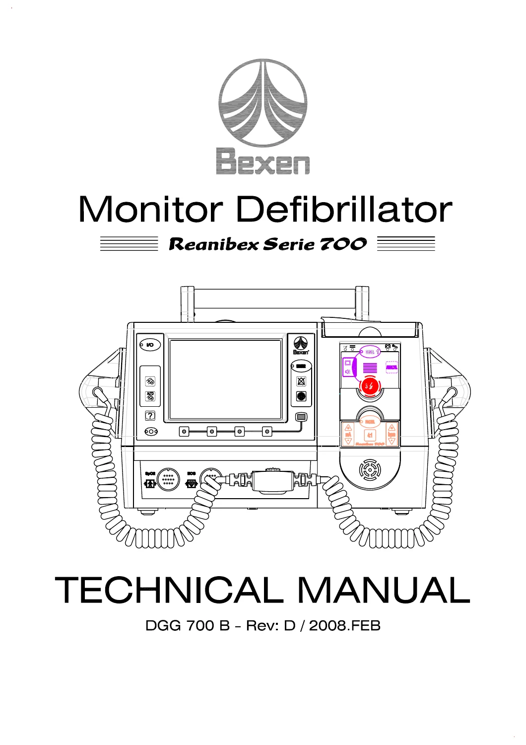
Bexen REANIBEX Serie 700 Monitor Defibrillator Technical Service Manual 2008
Original price was: $34.95.$19.95Current price is: $19.95.
Technical service manual for the Bexen REANIBEX Serie 700 monitor/defibrillator, covering safety, technical specifications, block and connection diagrams, CPU and high-voltage electronics, optional pacemaker circuitry, display and printer boards, self-testing, error codes, troubleshooting, component replacement guidance, and detailed parts lists.
Description
Bexen REANIBEX Serie 700 Monitor Defibrillator Technical Service Manual 2008
The Bexen REANIBEX Serie 700 Monitor Defibrillator Technical Service Manual 2008 is a detailed technical reference for the REANIBEX Serie 700 monitor/defibrillator manufactured by OSATU S.Coop. It combines equipment description, service-level electronic architecture, operating specifications, diagnostic routines, board-level information, troubleshooting procedures, component lists, and replacement guidance in one document. The manual is particularly useful when work goes beyond routine operation and requires understanding how the monitor, defibrillator, power supply, patient interface, optional pacemaker, optional pulse oximetry, recorder, display, Compact Flash system, and internal self-tests interact.
The manual identifies the unit as a portable monitor/defibrillator with Monitor mode, Manual Defibrillator mode, optional Semi-Automatic Defibrillator mode, and optional external transcutaneous Pacemaker mode. It also documents ECG monitoring through 3, 5, or 10 lead patient cables, reusable paddles, and multifunction electrodes, along with optional SpO2 monitoring and optional data recording. Detailed diagrams show the physical layout of the unit, connectors, front panel functions, internal board relationships, and the circuitry used for energy charging, discharge, battery charging, patient impedance measurement, and signal processing.
File Details
- Manual type: Technical Manual
- Brand/model: Bexen REANIBEX Serie 700
- Document number: DGG 700 B
- Revision: D
- Date: February 2008
- Language: English
- Pages: 162
- File format: PDF
Equipment Functions and Service Scope
This REANIBEX Serie 700 technical manual starts with safety and preventive-maintenance information before moving into the construction and service architecture of the unit. It describes the front, upper, and rear views; identifies the patient cable, pulse oximetry, multifunction, power, recorder, and paddle connections; and explains the controls used in monitor, defibrillator, and pacemaker operation. The screen layout, display resolution, ECG presentation, alarm indications, device status symbols, battery symbols, and accessory interfaces are also covered.
The technical specifications section provides service-relevant operating data for the monitor, defibrillator, optional pulse oximeter, optional pacemaker, screen, recorder, data storage, battery, mains supply, direct external supply, environmental limits, and physical dimensions. Defibrillation is described as a truncated exponential biphasic waveform with energy compensation based on patient impedance. The document also gives the selectable manual defibrillation energy levels for external and internal paddles, charge-time information, output-energy accuracy, synchronization functions, semi-automatic defibrillation behavior, pacemaker pulse width and current/frequency ranges, recorder speed, Compact Flash capacity, battery endurance, supply ranges, and operating/storage conditions.
Internal Electronics and Board-Level Information
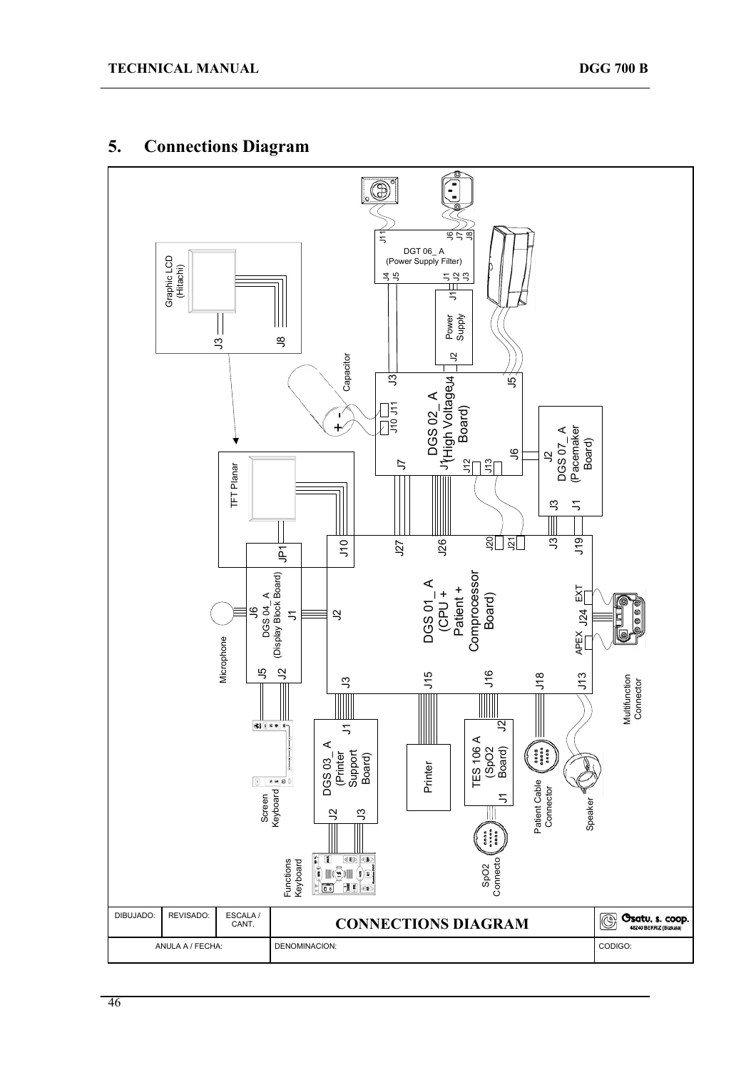
A major portion of the Bexen REANIBEX Serie 700 Monitor Defibrillator Technical Service Manual 2008 is devoted to the internal electronics. The general block diagram and connections diagram show how the CPU, high-voltage section, display, printer support, optional pacemaker, optional SpO2 board, power-supply filter, paddles, electrodes, patient cable, screen, recorder, speaker, microphone, Compact Flash memory, and external supplies are interconnected.
IMAGES PREVIEW
The CPU board chapter divides the board into control, patient monitor, and optional coprocessor functions. It explains how the unit controls the high-voltage board, optional SpO2 and pacemaker boards, recorder, screen, keyboards, audio, and other modules. The patient-monitor section covers ECG capture and filtering, QRS detection, patient impedance measurement, patient-cable identification, loose-lead detection, and communication with reusable paddles. The impedance-measurement discussion includes the injected test signal and the impedance ranges used to distinguish short circuit, patient connected, electrodes badly connected, and patient not connected conditions.
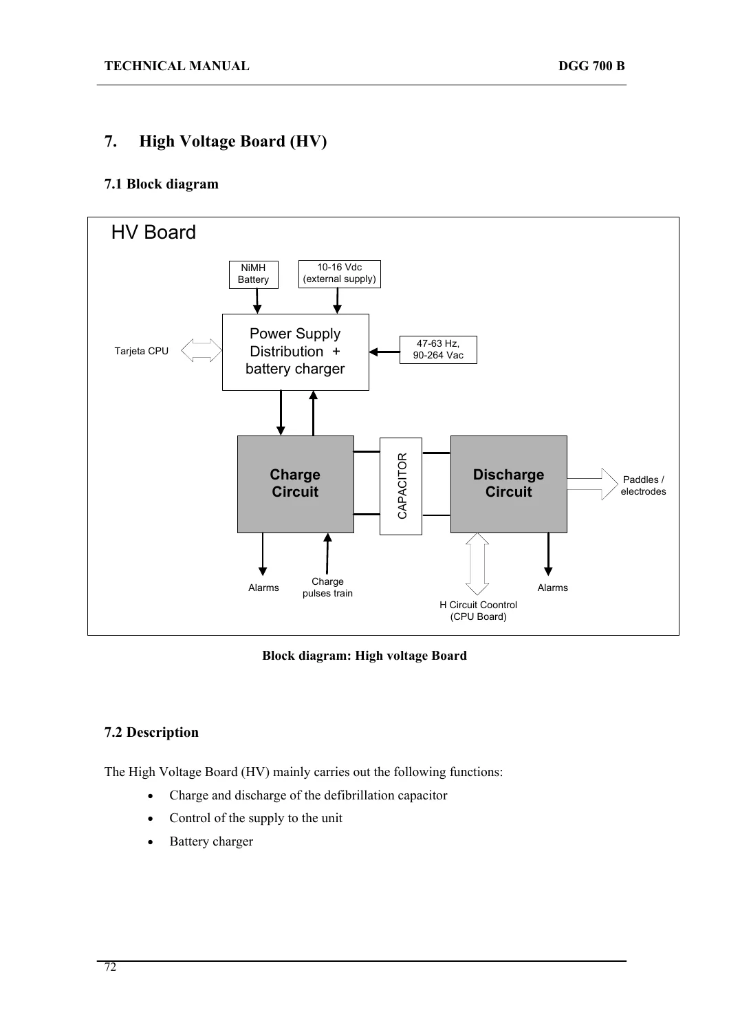
The high-voltage board section explains the charge and discharge process of the defibrillation capacitor, power-supply distribution, internal battery charging, patient-impedance verification before and after charging, and the internal discharge logic used when a shock is not delivered within the permitted time. Board block diagrams, component-location drawings, and extensive lists of materials identify many individual electronic components and references used on the CPU and HV assemblies.
The optional pacemaker board chapter documents its constant-current pulse generation, pulse monitoring, protections, component locations, and parts list. Separate sections cover the display board, printer support board, and supply filter board, including their functions, block diagrams, component layouts, and material lists. For technicians tracing faults between modules, this gives a clearer picture of which board is responsible for each function and how signals and power are routed through the unit.
Self-Testing, Error Codes and Troubleshooting
The REANIBEX Serie 700 incorporates self-tests at start-up and during operation, and this manual explains those checks in detail. The self-test chapter lists tests for FLASH and RAM memory, DUART, real-time clock, supply, battery, ambient temperature, defibrillator circuits, patient monitoring, optional coprocessor, optional pacemaker, pulse oximetry, recorder, paddles/patient cable, and Compact Flash. It also explains the manual Hardware Test, Accessories Test, Front Panel Test, and Paddles Interface Test available through Configuration mode.
The troubleshooting section is one of the most practical parts of the manual. Error codes are grouped by subsystem, including general errors, patient subsystem faults, high-voltage charging and discharge circuit faults, pacemaker errors, pulse oximetry errors, printer errors, coprocessor errors, real-time clock errors, and battery errors. The following test descriptions explain what the unit checks internally and the conditions that can trigger specific codes. This includes CPU and supply checks, patient-monitor calibration and ECG tests, coprocessor communication, defibrillator charging and discharge tests, semiconductor and relay tests, pacemaker current and protection tests, pulse oximeter identification, and recorder status checks.
A problem-summary table then connects observed symptoms with service actions. It covers physical damage, failure to start, keyboard and indicator faults, incorrect date/time, patient-impedance problems, poor ECG signals, missing SpO2 readings, display and audible-message problems, incorrect rhythm-response behavior, defibrillator capacitor charging and discharge faults, pacemaker output faults, recorder problems, and Compact Flash issues. The guidance includes connection checks, use of built-in tests, module isolation, and replacement of specific boards or components where required.
Chapters Covered
- 1. Warnings
- Safety
- General
- Design and Fabrication
- Preventive Maintenance
- Check list
- Cleaning
- Storage
- Explosions
- Batteries
- Repairs and Inspection
- Recycling
- REANIBEX 700 Series Symbols
- On-screen symbols
- Battery symbols
- Unit labels
- Battery labels
- 2. General description
- Front view
- Upper view
- Rear view
- Front panel
- Screen
- Paddles, electrodes and patient cable
- 3. Technical specifications
- General
- Defibrillation waveform
- 4. General Block Diagram
- 5. Connections Diagram
- 6. CPU Board
- Block Diagram
- Description
- Location of Components
- List of Materials
- 7. High Voltage Board (HV)
- Block diagram
- Description
- Location of Components
- List of Materials
- 8. Pacemaker Board (Optional)
- Block diagram
- Description
- Location of Components
- List of Materials
- 9. Display Board
- Block diagram
- Description
- Location of Components
- List of Materials
- 10. Printer Support Board
- Block diagram
- Description
- Location of Components
- List of Materials
- 11. Supplies Filter Board
- Block diagram
- Description
- Location of Components
- List of Materials
- 12. Unit Self-Testing
- Description of the self-checks
- Hardware Test
- Accessories Test
- Front Panel Test
- Paddles Interface Test
- 13. Troubleshooting
- Error Codes
- Tests
- Actions to be Performed
- Problems Summary Table
- Appendix
- Manufacturer’s guide and declaration of Electromagnetic Compatibility
- Essential functions
- Procedures for Changing Components
- Assembly Diagrams
Taken together, these chapters provide a complete technical view of the REANIBEX Serie 700 from external controls and specifications down to the internal boards, high-voltage circuitry, patient-monitor signal path, self-diagnostic logic, error reporting, and service checks. The inclusion of component-location drawings and long lists of materials makes the manual useful not only for identifying a failed module but also for understanding the electronic construction of individual assemblies.
Component Replacement and Service Safety
The appendix includes procedures for changing components and emphasizes the hazards associated with the energy-storage capacitor and high-voltage sections. It instructs qualified personnel to disconnect cables before opening the unit, confirm that stored energy has been discharged, use antistatic precautions, label cables and connections for reassembly, and perform a Hardware Test after reassembly. The manual also calls for checking discharged energy at different energy levels after service work. These instructions make the service content especially important when the unit must be opened, boards are handled, or internal modules are replaced.
Use This Manual for Accurate REANIBEX 700 Service Work
The Bexen REANIBEX Serie 700 Monitor Defibrillator Technical Service Manual 2008 supports technical work ranging from preventive checks and built-in diagnostics to fault isolation, board replacement, connection tracing, high-voltage circuit testing, pacemaker verification, ECG and patient-interface troubleshooting, recorder and display checks, and investigation of error codes. Having the documented procedures, limits, diagrams, component references, and test logic available helps technicians work from the unit’s actual design rather than relying on guesswork when diagnosing faults or confirming correct operation.
After purchase, the manual is delivered instantly as a PDF download. There is no physical shipping delay, and the file can be viewed on compatible computers, tablets, and phones or printed for workshop and service use.




Reviews
There are no reviews yet.