Description
Bobcat E85 Compact Excavator Service Manual – Complete PDF Workshop Guide
The Bobcat E85 Compact Excavator Service Manual (document number 7320318enUS) is the comprehensive workshop resource for professional technicians and serious owner-operators maintaining the E85 compact excavator. This 968-page PDF covers everything from routine maintenance intervals and fluid specifications to complete engine teardown, hydraulic pump calibration, electrical diagnostics, and undercarriage service. Whether you are adjusting valve clearance on the Bobcat D24NAP Tier 4 engine, troubleshooting a swing motor issue, or rebuilding a boom cylinder, this manual provides the procedures, torque values, and specifications needed to complete the job accurately.
File Details
- Manual Type: Service Manual
- Brand: Bobcat
- Model: E85 Compact Excavator
- Engine: Bobcat D24NAP Tier 4 diesel
- Language: English
- Page Count: 968 pages
- File Format: PDF
- Document Number: 7320318enUS
The manual covers serial number B48411001 and above, with specific sections addressing earlier and later model variations where procedures differ. This makes it suitable for a wide range of E85 machines in service today.
Chapters Covered
- Safety Instructions, Fire Prevention, Serial Number Locations, and Excavator Identification
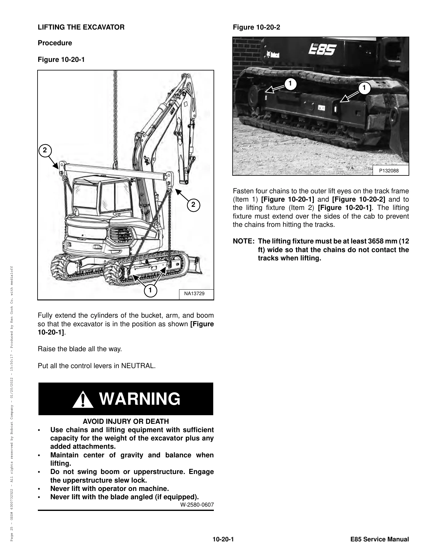
- Lifting and Blocking the Excavator, Lifting the Excavator, and Transporting on a Trailer
- Operator Cab (ROPS/TOPS/FOPS) and Cab Door/Window Service
- Maintenance Intervals and Service Schedule
- Air Cleaner Service and Cab Filters
- Engine Cooling System, Fuel System, and Engine Lubrication System
- Hydraulic System Maintenance and Fluid Service
- Lubricating the Excavator and Pivot Pins
- Travel Motor Service
- Emergency Exit, Seat Belt, and Control Console Lockouts
- Towing the Excavator and Remote Start Tool
- Hydraulic System Troubleshooting
- Hydraulic Cylinders – Boom, Arm, Boom Swing, Bucket, Blade, and Clamp
- Valves – Main Relief, Port Relief, Cross Port Relief, and Pressure Reducing
- Hydraulic Control Valve
- Hydraulic Pump – Testing, Removal, Disassembly, and Assembly
- Manifold Assembly / Accumulator
- Travel Motor and Swivel Joint
- Swing Motor and Swing Motor Drive Carrier
- Control Pattern Selector Valve
- Right and Left Control Levers (Joysticks)
- Hydraulic Filter Mount and Hydraulic Reservoir
- Oil Cooler and Blade Control Lever
- Travel Control Valve
- Removing Air from the Hydraulic System
- Manifold (Pin Grabber) and Secondary Auxiliary Valve
- Valve (Boom Lock) and Valve (Arm Lock)
- Blade Removal and Installation
- Track Undercarriage Components – Rubber, Steel, and Segmented Track
- Track Maintenance and Damage Identification
- Swing Circle Gear
- Upperstructure Removal and Installation
- Cab – Removal, Door, Windows, and Glass
- Seat, Right Console, and Left Console
- Upperstructure Covers, Counterweight, and Travel Levers
- Floor Mat, Fuel Tank, Horn, and Swing Frame
- Boom, Arm, Bucket, and Clamp
- Tailgate, Quick Coupler (Pin Grabber), and Side Covers
- Electrical System Information and Troubleshooting
- Battery, Alternator, and Starter
- Lights, Magnetic Lockout Sensor, and Fuel Level Sender
- Diagnostic Service Codes
- Control Panel Setup and Instrument Panel
- Controllers – Gateway, Auxiliary, and Pin Grabber
- Engine Control Unit (ECU)
- Key Switch, Wiper Motor, and Motion Alarm System
- Service PC (Laptop Computer) and Shut-Off Switch
- Travel Motor Auto-Shift and Auto Idle Pressure Sensor
- Bobcat Machine IQ Wireless Communications
- Engine Information, Specifications, and Torque Values
- Diesel Oxidation Catalyst (DOC)
- Air Cleaner, Engine Cooling System, and Lubrication System
- Fuel System – Transfer Pump, High Pressure Pump, Injectors
- Cylinder Head – Glow Plugs, Valve Clearance, Removal and Installation
- Crankshaft and Pistons – Removal, Inspection, and Installation
- Camshaft, Gearcase, Turbocharger, and Flywheel
- Exhaust Gas Recirculation (EGR) System
- Heating, Ventilation and Air Conditioning – System Flow, Troubleshooting, and Service
- Specifications – Excavator, Engine, Torque, Hydraulic, and Conversions
- Alphabetical Index
What This Service Manual Covers in Detail
The Bobcat E85 service manual opens with safety instructions and fire prevention guidelines, then moves into excavator identification, serial number locations, and lifting procedures. The maintenance section provides a complete service schedule with intervals at 10, 50, 250, 500, 1000 hours and 24 months, covering engine oil and filter changes, fuel filter service, hydraulic filter replacement, track tension checks, and lubrication points.
Complete PDF Bookmark Tree
Complete Bookmarks
The complete bookmarks in the “Bobcat E85 Compact Excavator Service Manual – PDF Download” are as follows:
MAINTENANCE SAFETYp. 3
CONTENTSp. 5
+FOREWORDp. 7
FOREWORDp. 9
SAFETY INSTRUCTIONSp. 11
+FIRE PREVENTIONp. 13
Maintenancep. 13
Operationp. 13
Electricalp. 13
Hydraulic Systemp. 13
Fuelingp. 13
Startingp. 13
Spark Arrester Exhaust Systemp. 13
Welding And Grindingp. 14
Fire Extinguishersp. 14
+SERIAL NUMBER LOCATIONSp. 15
Excavator Serial Numberp. 15
Engine Serial Numberp. 15
DELIVERY REPORTp. 16
EXCAVATOR IDENTIFICATIONp. 17
+SAFETY AND MAINTENANCEp. 19
+LIFTING AND BLOCKING THE EXCAVATORp. 23
+LIFTING THE EXCAVATORp. 25
+OPERATOR CAB (ROPS / TOPS)p. 27
Descriptionp. 27
Cab Doorp. 28
Front Windowp. 29
Front Wiperp. 30
Window Washer Reservoirp. 30
Right Side Windowsp. 31
+OPERATOR CAB (ROPS / TOPS / FOPS)p. 33
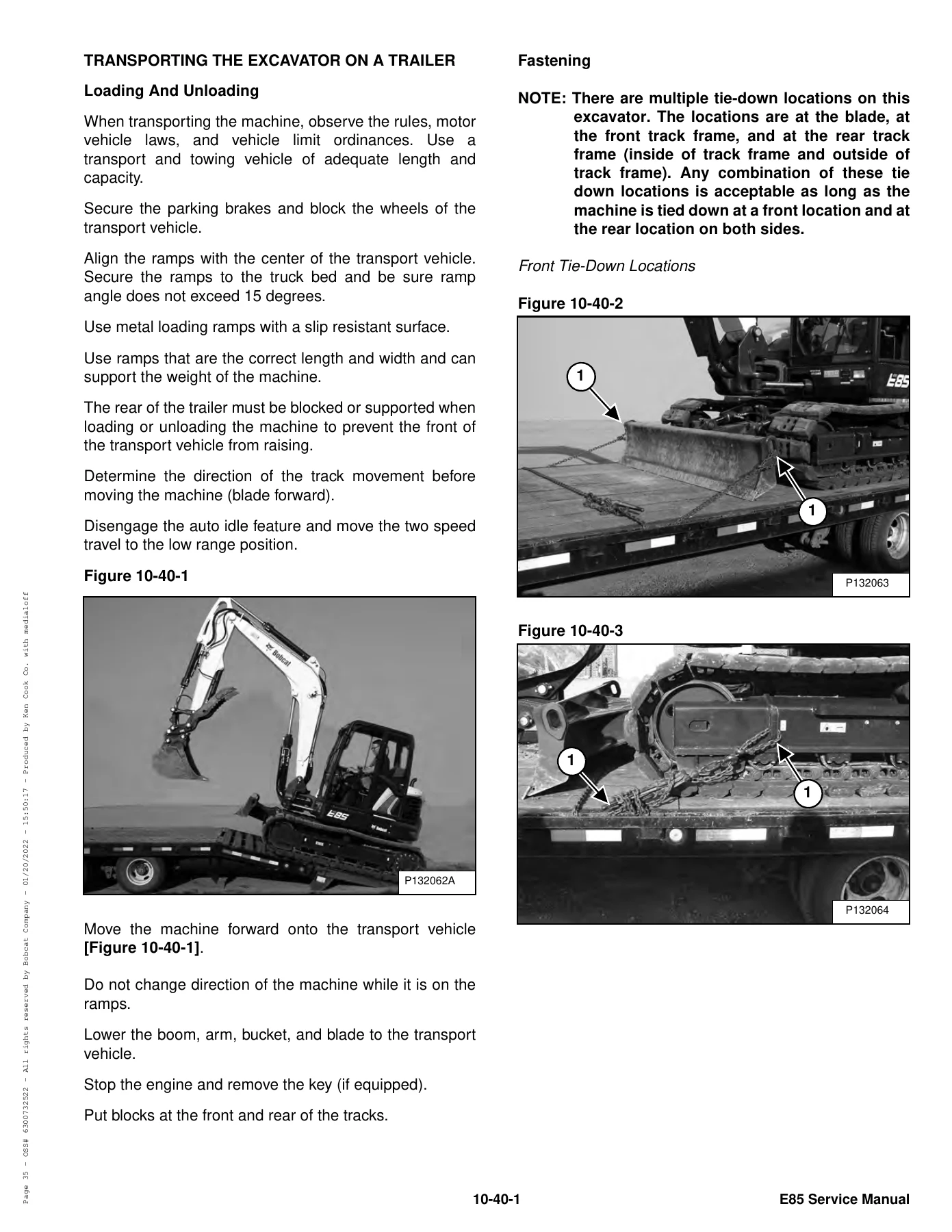
+TRANSPORTING THE EXCAVATOR ON A TRAILERp. 35
Loading And Unloadingp. 35
Fasteningp. 35
+TAILGATEp. 37
Opening And Closingp. 37
Adjusting The Latchp. 37
+RIGHT SIDE COVERp. 39
+CENTER COVERp. 41
Removal And Installationp. 41
+SERVICE SCHEDULEp. 43
Maintenance Intervalsp. 43
+AIR CLEANER SERVICEp. 45
Replacing The Filter Elementsp. 45
+CAB FILTERSp. 47
Cleaning And Maintenancep. 47
+ENGINE COOLING SYSTEMp. 49
Cleaningp. 49
Checking Levelp. 50
Removing And Replacing Coolantp. 51
+FUEL SYSTEMp. 53
Fuel Specificationsp. 53
Biodiesel Blend Fuelp. 53
Filling The Fuel Tankp. 54
Fuel Filtersp. 55
Removing Air From The Fuel Systemp. 56
Replacing The Fuel Tank Breatherp. 56
Draining The Fuel Tankp. 57
+ENGINE LUBRICATION SYSTEMp. 59
Checking And Adding Engine Oilp. 59
Engine Oil Chartp. 59
Removing And Replacing Oil And Filterp. 60
+HYDRAULIC SYSTEMp. 61
Checking And Adding Hydraulic Oilp. 61
Hydraulic / Hydrostatic Fluid Chartp. 62
Removing And Replacing The Hydraulic Filtersp. 62
Removing And Replacing The Hydraulic Fluidp. 64
Checking Swing Motor Gear Box Fluid Levelp. 65
Removing And Replacing Swing Motor Gear Box Fluidp. 65
+LUBRICATING THE EXCAVATORp. 67
Lubrication Locationsp. 67
+PIVOT PINSp. 71
Inspection And Maintenancep. 71
+TRAVEL MOTORp. 73
Checking And Adding Oilp. 73
Removing And Replacing Oilp. 73
+EMERGENCY EXITp. 75
Right Side Rear Windowp. 75
Front Windowp. 75
+SEAT BELTp. 77
Inspection And Maintenancep. 77
+CONTROL CONSOLE LOCKOUTSp. 79
Inspection And Maintenancep. 79
+TOWING THE EXCAVATORp. 81
+REMOTE START TOOL KIT – MEL1563p. 83
Remote Start Tool – MEL1563p. 83
Service Tool Harness Control – MEL1565p. 84
Service Tool Harness Communicator – MEL1566p. 85
+REMOTE START TOOL (SERVICE TOOL) KIT – 7217666p. 87
Descriptionp. 87
Remote Start Tool (Service Tool) – 7022042p. 88
Excavator Service Tool Harness – 6689747p. 89
Computer Service Tool Harness – 6689746p. 90
+HYDRAULIC SYSTEMp. 91
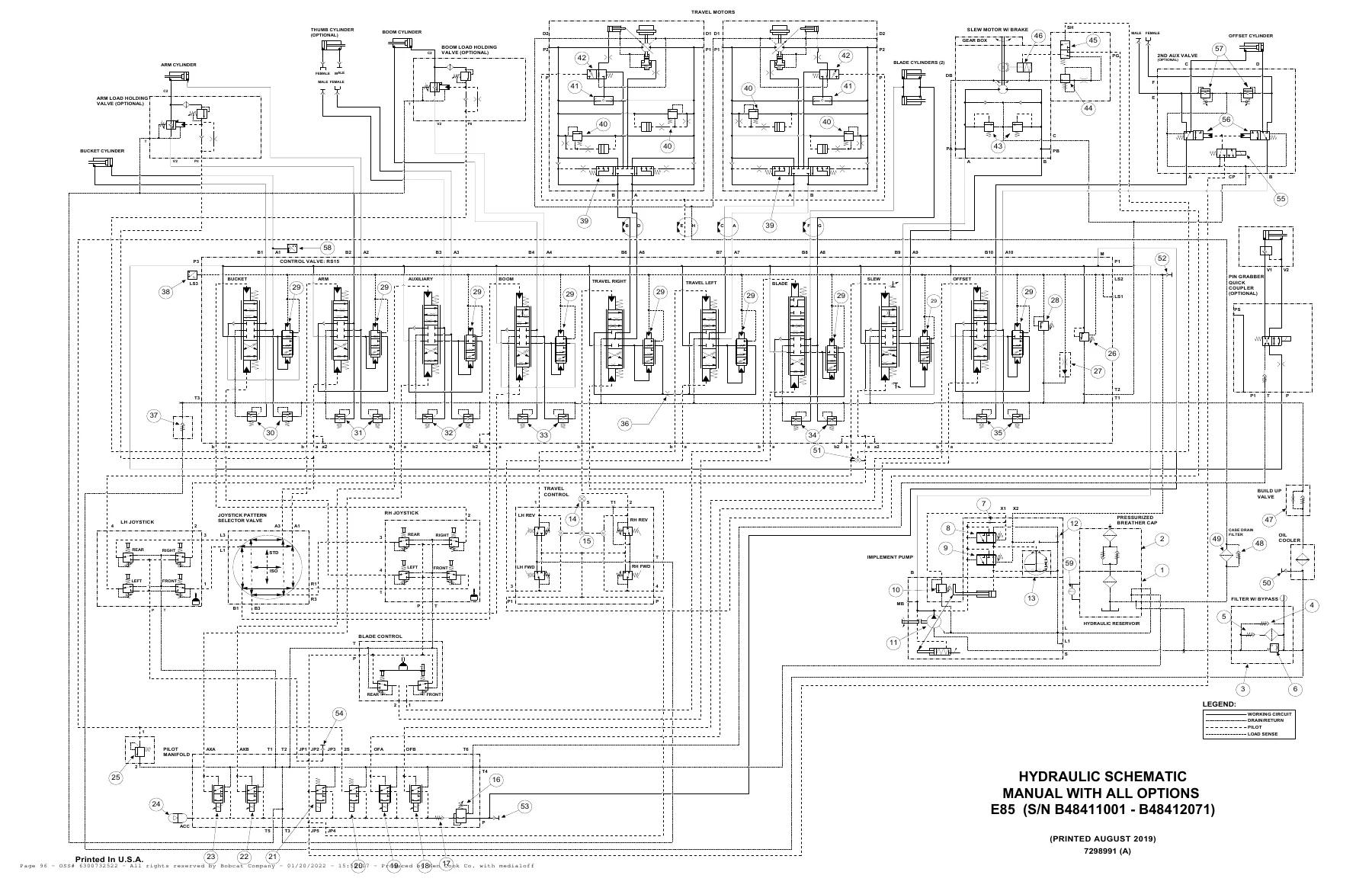
HYDRAULIC / HYDROSTATIC SCHEMATICSp. 95
+HYDRAULIC SYSTEM INFORMATIONp. 99
Glossary Of Hydraulic / Hydrostatic Symbolsp. 99
Troubleshooting The Hydraulic Circuitp. 102
Troubleshooting The Cylinder Circuitp. 103
Troubleshooting The Swing (Upperstructure Slew) Circuitp. 104
Troubleshooting The Travel Circuitp. 105
+CYLINDER (BOOM)p. 107
Testingp. 107
Removal And Installationp. 109
Parts Identificationp. 111
Disassemblyp. 112
Assemblyp. 120
+CYLINDER (ARM)p. 129
Testingp. 129
Removal And Installationp. 131
Parts Identificationp. 133
Disassemblyp. 134
Assemblyp. 141
+CYLINDER (BOOM SWING)p. 149
Testingp. 149
Removal And Installationp. 150
Parts Identificationp. 152
Disassemblyp. 153
Assemblyp. 155
+CYLINDER (BUCKET)p. 159
Testingp. 159
Removal And Installationp. 159
Parts Identificationp. 162
Disassemblyp. 163
Assemblyp. 171
+CYLINDER (BLADE)p. 179
Testingp. 179
Removal And Installationp. 180
Parts Identificationp. 181
Disassemblyp. 182
Assemblyp. 190
+CYLINDER (CLAMP)p. 197
Testingp. 197
Removal And Installationp. 198
Parts Identificationp. 199
Disassemblyp. 200
Assemblyp. 203
+VALVES (MAIN RELIEF)p. 207
Testing And Adjustingp. 207
+VALVES (PORT RELIEF)p. 209
Testing And Adjusting Port Relief Valve Pressurep. 209
+VALVES (CROSS PORT RELIEF)p. 211
Testing And Adjustingp. 211
Removal And Installationp. 214
+VALVES (PRESSURE REDUCING)p. 215
Testing And Adjustingp. 215
+HYDRAULIC CONTROL VALVEp. 217
Descriptionp. 217
Removal And Installationp. 217
Parts Identificationp. 220
Disassembly And Assemblyp. 221
Inlet Valve Section Disassembly And Assemblyp. 225
Valve Section Disassembly And Assemblyp. 228
+HYDRAULIC PUMPp. 231
Hydraulic Pump Work Sheetp. 231
Pump Testingp. 235
Removal And Installationp. 247
Coupler Removal And Installationp. 249
Hydraulic Pump Startupp. 250
Torque Limiter Valve Parts Identificationp. 252
Torque Limiter Valve Removalp. 253
Torque Limiter Valve Disassemblyp. 254
Torque Limiter Valve Assemblyp. 258
Initial Torque Limiter Valve Settingp. 261
Torque Limiter Valve Installationp. 263
Pump Control Parts Identificationp. 264
Pump Control Removal And Installationp. 265
Pump Control Disassembly And Assemblyp. 266
Parts Identificationp. 271
Disassemblyp. 272
Assemblyp. 281
+MANIFOLD ASSEMBLY / ACCUMULATORp. 291
Descriptionp. 291
Removal And Installationp. 292
Parts Identificationp. 293
Disassembly And Assemblyp. 294
+TRAVEL MOTORp. 301
Removal And Installationp. 301
Parts Identificationp. 302
Parts Identification Gear Reduction Hubp. 303
Disassemblyp. 304
Assemblyp. 315
+SWIVEL JOINTp. 327
Removal And Installationp. 327
Parts Identificationp. 328
Disassembly And Assemblyp. 329
+SWING MOTORp. 333
Removal And Installationp. 333
Parts Identificationp. 335
Disassembly And Assemblyp. 336
+SWING MOTOR (DRIVE CARRIER)p. 345
Removal And Installationp. 345
Parts Identificationp. 346
Disassembly And Assemblyp. 347
+CONTROL PATTERN SELECTOR VALVEp. 351
Removal And Installationp. 351
Parts Identificationp. 352
Disassembly And Assemblyp. 353
+RIGHT CONTROL LEVER (JOYSTICK)p. 355
Testingp. 355
Handle Removal And Installationp. 356
Joystick Assembly Removal And Installationp. 358
Parts Identificationp. 359
Disassemblyp. 360
Assemblyp. 365
+LEFT CONTROL LEVER (JOYSTICK)p. 371
Testingp. 371
Handle Removal And Installationp. 372
Joystick Assembly Removal And Installationp. 374
Parts Identificationp. 375
Disassemblyp. 376
Assemblyp. 381
+HYDRAULIC FILTER MOUNTp. 387
Removal And Installationp. 387
+HYDRAULIC RESERVOIRp. 389
Removal And Installationp. 389
+OIL COOLERp. 393
Removal And Installationp. 393
+BLADE CONTROL LEVERp. 395
Handle Removal And Installationp. 395
Removal And Installationp. 397
Parts Identificationp. 399
Disassembly And Assemblyp. 400
+CASE DRAIN FILTER MOUNTp. 405
Removal And Installationp. 405
+TRAVEL CONTROL VALVEp. 407
Removal And Installationp. 407
Parts Identificationp. 408
Disassembly And Assemblyp. 409
+REMOVING AIR FROM THE HYDRAULIC SYSTEMp. 415
+MANIFOLD (PIN GRABBER)p. 417
Removal And Installationp. 417
Parts Identificationp. 418
Disassembly And Assemblyp. 419
+SECONDARY AUXILIARY VALVEp. 421
Removal And Installationp. 421
Parts Identificationp. 423
Disassembly And Assemblyp. 424
+VALVE (BOOM LOCK)p. 427
Removal And Installationp. 427
+VALVE (ARM LOCK)p. 429
Removal And Installationp. 429
+UNDERCARRIAGEp. 431
+BLADEp. 433
Removal And Installationp. 433
+TRACK UNDERCARRIAGE COMPONENTS (RUBBER TRACK)p. 435
Descriptionp. 435
Track Lug Heightp. 435
Checking Tensionp. 436
Adjusting Tensionp. 437
Track Removal And Installationp. 438
Idler Removal And Installationp. 440
Idler Parts Identificationp. 441
Idler Disassemblyp. 442
Idler Assemblyp. 445
Track Tensioner Removal And Installationp. 450
Track Tensioner Parts Identificationp. 451
Track Tensioner Disassembly And Assemblyp. 452
Roller Removal And Installationp. 453
Lower Roller Parts Identificationp. 454
Lower Roller Disassemblyp. 455
Lower Roller Assemblyp. 458
Upper Roller Parts Identificationp. 464
Upper Roller Disassembly And Assemblyp. 465
Sprocket Removal And Installationp. 468
+TRACK UNDERCARRIAGE COMPONENTS (STEEL TRACK)p. 469
Descriptionp. 469
Checking Tensionp. 470
Adjusting Tensionp. 471
Track Removalp. 472
Track Installationp. 474
Idler Removal And Installationp. 475
Idler Parts Identificationp. 476
Idler Disassemblyp. 477
Idler Assemblyp. 480
Track Tensioner Removal And Installationp. 485
Track Tensioner Parts Identificationp. 486
Track Tensioner Disassembly And Assemblyp. 487
Roller Removal And Installationp. 488
Lower Roller Parts Identificationp. 489
Lower Roller Disassemblyp. 490
Lower Roller Assemblyp. 493
Upper Roller Parts Identificationp. 499
Upper Roller Disassembly And Assemblyp. 500
Sprocket Removal And Installationp. 503
Guide Plate Removal And Installationp. 503
+TRACK UNDERCARRIAGE COMPONENTS (SEGMENTED TRACK)p. 505
Descriptionp. 505
Rubber Pad Removal And Installationp. 505
Guide Plate Removal And Installationp. 506
+TRACK MAINTENANCEp. 507
Track Damage Identificationp. 507
+SWING CIRCLE GEARp. 519
Swing Bearing Removalp. 519
Swing Bearing Installationp. 520
+UPPERSTRUCTURE AND SWING SECTIONp. 521
+UPPERSTRUCTUREp. 523
Removalp. 523
Installationp. 525
+CABp. 527
Removal And Installationp. 527
Door Removal And Installationp. 531
Door Latch Removal And Installationp. 532
Hold Open Latch Removal And Installationp. 533
Front Window Removal And Installationp. 534
Front Window Disassembly And Assemblyp. 535
Front Window Adjustmentp. 537
Right Side Rear Sliding Window Removal And Installationp. 539
Glass Removalp. 540
+SEATp. 541
Removal And Installationp. 541
+RIGHT CONSOLEp. 543
Console Cover Removal And Installationp. 543
+LEFT CONSOLEp. 549
Lower Console Cover Removal And Installationp. 549
Upper Console Cover Removal And Installationp. 550
Compression Spring Removal And Installationp. 553
Lock Lever Removal And Installationp. 555
Console Removal And Installationp. 555
+LEFT UPPERSTRUCTURE COVERp. 557
Removal And Installationp. 557
+RIGHT UPPERSTRUCTURE COVERp. 559
Removal And Installationp. 559
+COUNTERWEIGHTp. 561
Removal And Installationp. 561
Add-On Counterweight Removal And Installationp. 563
+TRAVEL LEVERS AND PEDALSp. 565
Removal And Installationp. 565
Disassembly And Assemblyp. 566
+FLOOR MATp. 567
Removal And Installationp. 567
+FUEL TANKp. 569
Removal And Installationp. 569
Fuel Tank Fitting Removal And Installationp. 570
+HORNp. 571
Removal And Installationp. 571
+SWING FRAMEp. 573
Removal And Installationp. 573
Boom Swing Frame Hose Routingp. 576
Bushing Removalp. 577
Bushing Installationp. 578
+BOOMp. 579
Removal And Installationp. 579
+ARMp. 581
Removal And Installationp. 581
Arm To Boom Bushing Removal And Installationp. 582
Arm To Bucket And Bucket Link Bushing Removal And Installationp. 583
+BUCKETp. 585
Bucket Teeth Removal And Installationp. 585
Bucket Side Cutting Edge Removal And Installationp. 586
+CLAMPp. 587
Removal And Installationp. 587
+TAILGATEp. 589
Removal And Installationp. 589
Latch Removal And Installationp. 590
+QUICK COUPLER (PIN GRABBER)p. 591
Troubleshootingp. 591
Daily Inspectionp. 592
Removal And Installationp. 593
Parts Identificationp. 594
Disassembly And Assemblyp. 595
+RIGHT SIDE COVERp. 597
Removal And Installationp. 597
Latch Removal And Installationp. 598
+TOOL BOXp. 599
Removal And Installationp. 599
+CENTER COVERp. 601
Removal And Installationp. 601
+ELECTRICAL SYSTEM AND ANALYSISp. 603
ELECTRICAL SCHEMATICSp. 607
+ELECTRICAL SYSTEM INFORMATIONp. 665
Troubleshooting Chartp. 665
Descriptionp. 666
Fuse And Relay Location / Identificationp. 666
Shut-Off Switchp. 668
+BATTERYp. 669
Servicingp. 669
Using A Booster Battery (Jump Starting)p. 670
Removing And Installing The Batteryp. 671
+ALTERNATORp. 673
Belt Adjustmentp. 673
Belt Replacementp. 673
Charging System Inspectionp. 674
Alternator Voltage Testingp. 675
Low Voltage Testingp. 675
High Voltage Testingp. 676
Removal And Installationp. 677
Parts Identificationp. 679
+STARTERp. 681
Testingp. 681
Removal And Installationp. 682
Parts Identificationp. 683
+LIGHTSp. 685
Removal And Installationp. 685
Boom Light Removal And Installationp. 686
Boom Light Bulb Replacementp. 686
+MAGNETIC LOCKOUT SENSORp. 687
Removal And Installationp. 687
+FUEL LEVEL SENDERp. 689
Lower Fuel Level Sender Removal And Installationp. 689
Upper Fuel Level Sender Removal And Installationp. 689
Testingp. 690
+DIAGNOSTIC SERVICE CODESp. 691
Viewing Service Codesp. 691
Service Codes Listp. 692
+CONTROL PANEL SETUPp. 699
Panel Setup (Deluxe Instrument Panel)p. 699
Password Setup (Keyless Start Panel)p. 705
Password Setup (Deluxe Instrument Panel)p. 706
Password Lockout Featurep. 707
Maintenance Clockp. 708
+INSTRUMENT PANELp. 711
Removal And Installationp. 711
+CONTROLLER (GATEWAY AND AUXILIARY)p. 713
Descriptionp. 713
Gateway Controller Removal And Installationp. 713
Auxiliary Controller Removal And Installationp. 714
+CONTROLLER (PIN GRABBER)p. 715
Removal And Installationp. 715
+ENGINE CONTROL UNIT (ECU)p. 717
Descriptionp. 717
Cleaningp. 718
Removal And Installationp. 719
+KEY SWITCHp. 721
Removal And Installationp. 721
+WIPER MOTORp. 723
Removal And Installationp. 723
+MOTION ALARM SYSTEMp. 725
Descriptionp. 725
Inspectingp. 725
Adjusting Switch Positionp. 726
+SERVICE PC (LAPTOP COMPUTER)p. 727
Connecting The Remote Start Toolp. 727
Connecting Remote Start Tool (Service Tool)p. 727
+SHUT-OFF SWITCHp. 729
Removal And Installationp. 729
+TRAVEL MOTOR AUTO-SHIFTp. 731
Auto-Shift Drive System (If Equipped)p. 731
Troubleshootingp. 732
+AUTO IDLE PRESSURE SENSORp. 735
Descriptionp. 735
Removal And Installationp. 736
+BOBCAT MACHINE IQ WIRELESS COMMUNICATIONSp. 737
Descriptionp. 737
Controller Removal And Installationp. 737
Antenna Removal And Installationp. 740
Procedurep. 741
+ENGINE SERVICEp. 743
+ENGINE INFORMATIONp. 745
Descriptionp. 745
Specificationsp. 746
Sensor Locationp. 748
Torque Valuesp. 754
Troubleshootingp. 756
Engine Removal And Installationp. 758
Compression – Testing Using The Glow Plug Adapterp. 766
Compression – Testing Using The Injector Adapterp. 768
Injector Signal – Testingp. 770
Injector Signal – Testing (In-Line)p. 772
Oil Pressure Testing (At Oil Sensor On Block)p. 774
Oil Pressure Testing (At Turbocharger Oil Inlet)p. 777
+DIESEL OXIDATION CATALYST (DOC)p. 779
Removal And Installationp. 779
+AIR CLEANERp. 781
Housing Removal And Installationp. 781
+ENGINE COOLING SYSTEMp. 783
Oil Cooler / Radiator Removal And Installationp. 783
Fan Removal And Installationp. 786
Water Pump Removal And Installationp. 787
Thermostat Housing Removal And Installationp. 788
Testing The Thermostatp. 789
+LUBRICATION SYSTEMp. 791
Descriptionp. 791
Oil Pan Removal And Installationp. 792
Oil Pump Removal And Installationp. 793
Oil Pump Relief Valve Descriptionp. 794
Oil Pump Relief Valve Removal And Installationp. 794
Oil Cooler Removal And Installationp. 795
Oil Filter Head Removal And Installationp. 796
Oil Cooler Bypass Descriptionp. 797
Oil Cooler Bypass Removal And Installationp. 797
+FUEL SYSTEMp. 799
Descriptionp. 799
Transfer Pump / High Pressure Pump Removal And Installationp. 800
Fuel Temperature Sensor Removal And Installationp. 803
Fuel Cooler Removal And Installationp. 804
Fuel Recirculation Valve Removal And Installationp. 805
Fuel Injector Removal And Installationp. 806
Removing Air From The Fuel Systemp. 808
+CYLINDER HEADp. 809
Glow Plugs Testingp. 809
Glow Plug Removal And Installationp. 810
Valve Clearance Adjustmentp. 811
Cylinder Head Removal And Installationp. 813
Cylinder Head Disassembly And Assemblyp. 817
Cylinder Head Inspectionp. 818
Cylinder Head Top Clearancep. 819
Valve Step Heightp. 820
Valve Stem Heightp. 820
Valve Guidep. 821
Valvep. 821
Valve Springp. 822
Rocker Arm Shaft Disassembly And Assemblyp. 823
Rocker Arm Shaft Inspectionp. 824
Push Rod Inspectionp. 824
+CRANKSHAFT AND PISTONSp. 825
Piston And Connecting Rod Removal And Installationp. 825
Piston And Connecting Rod Inspectionp. 826
Crankshaft Removal And Installationp. 828
Cylinder Block Inspectionp. 831
Crankshaft Inspectionp. 833
Connecting Rod Inspectionp. 833
Engine Component Classp. 834
+CAMSHAFTp. 837
Removal And Installationp. 837
Inspectingp. 838
+GEARCASEp. 841
Gearcase Cover Removal And Installationp. 841
Gear Backlashp. 842
Gear Timingp. 843
Idle Gear Removal And Installationp. 844
Idle Gear Inspectionp. 844
+TURBOCHARGERp. 845
Descriptionp. 845
Removal And Installationp. 845
Inspectionp. 848
+FLYWHEEL AND HOUSINGp. 849
Hydraulic Pump Coupler Removal And Installationp. 849
Flywheel Removal And Installationp. 851
Ring Gear Removal And Installationp. 851
+EXHAUST GAS RECIRCULATION (EGR) SYSTEMp. 853
Removal And Installationp. 853
+HEATING, VENTILATION AND AIR CONDITIONINGp. 857
+AIR CONDITIONING SYSTEM FLOWp. 859
Descriptionp. 859
Chartp. 860
Componentsp. 861
Safety Equipmentp. 864
+REGULAR MAINTENANCEp. 865
Cleaning And Maintaining The Recirculation Filterp. 865
Cleaning And Maintaining The Fresh Air Filterp. 866
Air Conditioning Compressor Belt Adjustmentp. 867
Air Conditioning Compressor Belt Replacementp. 867
Condenserp. 868
Air Conditioning Lubricationp. 869
Evaporator / Heater Coilp. 869
Air Conditioning Service Chartp. 870
+TROUBLESHOOTINGp. 871
Blower Motor Does Not Operatep. 871
Blower Motor Operates Normally, But Air Flow Is Insufficientp. 871
Insufficient Cooling Although Air Flow And Compressor Operation Are Normalp. 871
The Compressor Operates Improperly Or Not At Allp. 871
Gauge Pressure Related Troubleshootingp. 872
Troubleshooting Treep. 873
Temperature / Pressure Chartp. 877
Temperature / Pressure Chartp. 879
Poor A/C Performancep. 880
HVAC Repair And Leaksp. 881
Electrical Systemp. 881
Engine Coolant Bypassing The Heater Valvep. 883
+SYSTEM CHARGING AND RECLAMATIONp. 885
Refrigerant Identificationp. 885
Reclamation And Charging With Recovery / Charging Unitp. 887
+COMPRESSORp. 889
Removal And Installationp. 889
Oilp. 890
Oil Checkp. 891
+CONDENSERp. 893
Removal And Installationp. 893
+RECEIVER / DRIERp. 895
Receiver / Drier Removal And Installationp. 895
Pressure Switch Removal And Installationp. 896
+EVAPORATOR / HEATER UNITp. 897
Removal And Installationp. 897
+THERMOSTATp. 899
Descriptionp. 899
Removal And Installationp. 900
+EXPANSION VALVEp. 903
Removal And Installationp. 903
+EVAPORATOR COILp. 905
Removal And Installationp. 905
+AUTO EVAPORATOR COILp. 907
Removal And Installationp. 907
+HEATER COILp. 909
Removal And Installationp. 909
+AUTO HEATER COILp. 911
Removal And Installationp. 911
+BLOWER FANp. 913
Removal And Installationp. 913
+AUTO BLOWER FANp. 915
Removal And Installationp. 915
+HEATER VALVEp. 917
Removal And Installationp. 917
+CONTROL PANELp. 919
Removal And Installationp. 919
+HVAC DUCTp. 921
Removal And Installationp. 921
+AUTO HVACp. 923
Descriptionp. 923
ATM Removal And Installationp. 923
ATM Diagnostic Codesp. 924
Blower Fan Drive Assembly Removal And Installationp. 925
De-Icing Sensor Removal And Installationp. 926
Inside And After Coil Sensor Testingp. 926
+SPECIFICATIONSp. 929
+EXCAVATOR SPECIFICATIONSp. 931
Machine Dimensionsp. 931
Performancep. 933
Controlsp. 933
Enginep. 934
Hydraulic Systemp. 935
Hydraulic Cylindersp. 935
Hydraulic Cycle Timesp. 936
Drive Systemp. 936
Slew Systemp. 936
Undercarriagep. 936
Capacitiesp. 936
Electricalp. 937
Tracksp. 937
Ground Pressurep. 937
+TECHNICAL SERVICE GUIDE SPECIFICATIONSp. 939
Enginep. 939
Engine Torquesp. 939
Cooling Systemp. 939
Excavator Torquesp. 939
+TORQUE SPECIFICATION FOR BOLTSp. 941
Torque For General SAE Boltsp. 941
Torque For General Metric Boltsp. 942
+HYDRAULIC CONNECTION SPECIFICATIONSp. 943
O-ring Face Seal Connectionp. 943
Straight Thread O-ring Fittingp. 943
Tubelines And Hosesp. 944
Flare Fittingp. 944
O-ring Flare Fittingp. 945
Port Seal Fittingp. 947
Push To Connect Fittingsp. 948
+HYDRAULIC FLUID SPECIFICATIONSp. 951
+CONVERSIONSp. 953
Decimal And Millimeter Equivalent Chartp. 953
U.S. To Metric Conversion Chartp. 954
+SERVICE TOOLS REQUIREDp. 955
Remote Start Toolsp. 955
Hydraulic Toolsp. 956
Engine Toolsp. 959
Electrical Toolsp. 961
General Toolsp. 962
HVAC Toolsp. 963
+ALPHABETICAL INDEXp. 965
SERVICE SCHEDULE SYMBOLSp. 967
The hydraulic system chapter is particularly extensive, spanning troubleshooting charts, cylinder service procedures for boom, arm, boom swing, bucket, blade, and clamp cylinders, valve testing and adjustment for main relief, port relief, cross port relief, and pressure reducing valves. The hydraulic pump section includes a detailed work sheet for six adjustments, pump testing procedures, torque limiter valve service, pump control disassembly, and complete pump teardown and assembly. The control valve chapter covers a ten-section closed center system with load sense relief, and the manifold assembly, travel motor, swivel joint, and swing motor all receive full removal, disassembly, inspection, and assembly treatment.
The E85 excavator electrical system chapter provides a troubleshooting chart, fuse and relay identification, battery servicing, alternator testing (including voltage testing procedures), starter testing, light service, diagnostic service codes with a comprehensive list, control panel setup for both standard and deluxe instrument panels, controller locations, engine control unit cleaning and removal, key switch, wiper motor, motion alarm system, and Bobcat Machine IQ wireless communications. The wiring schematic section includes 18 sheets covering power, ground, CAN bus, engine, hydraulics, frame, lights, radio, HVAC, options, and engine reference circuits.
The Bobcat D24NAP engine service chapter includes specifications, sensor locations, torque values, troubleshooting, engine removal and installation, compression testing using both glow plug and injector adapters, injector signal testing, oil pressure testing at both the oil sensor on the block and the turbocharger oil inlet. The cylinder head chapter covers glow plug testing, valve clearance adjustment, cylinder head removal and installation, disassembly and assembly, inspection, top clearance, valve step height, valve guide and spring service, and rocker arm shaft service. Crankshaft and pistons, camshaft, gearcase, turbocharger, flywheel and housing, and EGR system chapters round out the engine section.
The HVAC chapter covers air conditioning system flow, component identification, safety equipment, regular maintenance including filter cleaning and compressor belt service, troubleshooting trees, temperature and pressure charts, system charging and reclamation procedures, compressor removal and oil check, condenser, receiver/drier, evaporator/heater unit, thermostat, expansion valve, evaporator coil, heater coil, blower fan, heater valve, control panel, HVAC duct, and auto HVAC system with ATM diagnostic codes.
The specifications section provides machine dimensions, performance data, engine specifications, hydraulic system capacities, cylinder dimensions, hydraulic cycle times, drive system and slew system details, undercarriage specifications, fluid capacities, electrical specifications, track specifications, ground pressure, and torque specifications for both SAE and metric bolts.
Why This Manual Matters for E85 Owners and Technicians
Compact excavators like the Bobcat E85 are complex machines with interdependent hydraulic, electrical, and mechanical systems. Using incorrect procedures or specifications can lead to premature component failure, poor performance, or safety hazards. This E85 service repair manual provides the manufacturer’s recommended procedures for every major service task, including precise torque values, fluid capacities, pressure settings, and adjustment specifications that are not available in generic repair guides.
The diagnostic service codes list helps identify issues quickly, while the wiring schematics allow accurate electrical troubleshooting. The hydraulic system troubleshooting charts guide the technician through systematic diagnosis of common problems like slow operation, excessive heat, or complete loss of function in specific circuits.
Instant PDF Delivery
This Bobcat E85 workshop manual is delivered as an instant PDF download after purchase. There is no shipping, no waiting for a physical book, and no restrictions on where you can use it. The file can be viewed on any computer, tablet, or smartphone, and individual pages can be printed for use in the shop. The PDF format allows you to search for specific terms, jump to sections quickly, and keep the entire manual accessible on your device while working on the machine.
Whether you are performing routine maintenance, diagnosing an electrical fault, rebuilding a hydraulic cylinder, or completing a full engine overhaul, this service manual gives you the information needed to do the job correctly the first time.
Reviews
There are no reviews yet.