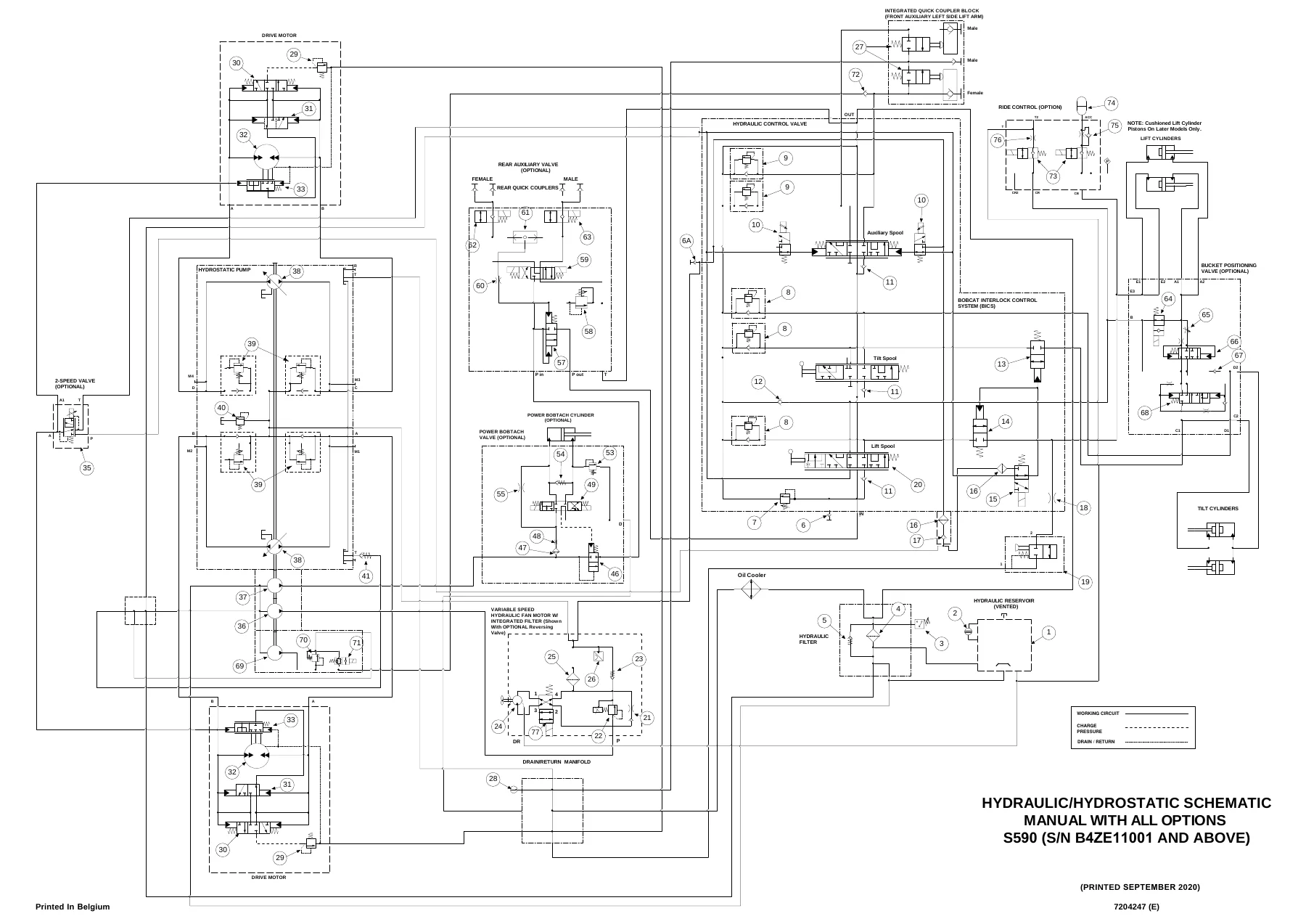
Description
The Bobcat S590 Skid-Steer Loader Service Manual is the full workshop reference for the S590 machine, written for the technicians who diagnose, strip, repair and reassemble the loader. It covers serial numbers B42E11001 & Above and B4U911001 & Above and runs close to a thousand pages across every major system on the machine, from the 2.4 L Bobcat turbocharged diesel and its diesel particulate filter and exhaust gas recirculation hardware, through the tandem hydrostatic pump and drive motors, the hydraulic control valve and cylinders, the chaincase and final drive, the controller network and complete wiring schematics, and the optional heating, ventilation and air conditioning package. This is not an owner’s summary. It is the shop manual a dealer technician works from, and it is the same document whether you are pulling a lift cylinder on a machine with 400 hours or calibrating a rebuilt hydrostatic pump on an SJC-equipped loader.
File Details
- Manual Type: Service Manual (workshop repair, maintenance and diagnostics)
- Brand: Bobcat
- Model: S590 Skid-Steer Loader
- Serial Numbers Covered: B42E11001 & Above, B4U911001 & Above (with B4ZE11001 & Above and B4RF11001 & Above referenced in the hydraulic and wiring schematic sets)
- Language: English
- Page Count: 969 pages
- File Format: PDF
- Document Number: 7417394enUS
- Wiring Schematic Sheets: 15 sheets (standard machine) and 17 sheets (SJC machine)
Chapters Covered
- Safety Instructions – fire prevention, electrical, hydraulic, fueling, starting, welding and grinding
- Maintenance – lifting and blocking, lift arm support, operator cab, transporting, towing, remote start tools, service schedule, engine air cleaner, engine cooling system, fuel system, engine lubrication, hydraulic/hydrostatic system, final drive transmission, Bob-Tach, lubrication points, tire maintenance, pivot pins, storage
- Hydraulic System – troubleshooting, glossary of hydraulic symbols, lift cylinder, tilt cylinder, Bob-Tach cylinder, main relief valve, standard hydraulic control valve, SJC hydraulic control valve, lift arm bypass control valve, hydraulic pump, high flow hydraulic pump, filters, fluid reservoir, oil cooler, bucket position valve, rear auxiliary diverter valve, Power Bob-Tach block, front auxiliary hydraulic coupler block, automatic ride control
- Hydrostatic System – hydrostatic drive motor, two-speed drive motor, hydrostatic motor carrier, two-speed motor carrier, charge pressure, hydrostatic pump, SJC hydrostatic pump, drive belt, two-speed valve block, drain manifold
- Drive System – brake, drive components, axle seals, axle/sprocket/bearings, drive chains, chaincase
- Mainframe – seat bar, operator cab, operator seat, suspension seat, Bob-Tach (hand lever and power), lift arms, rear grille, rear door, fuel tank, control pedals and linkages, control panel, SJC control panel, control handle/lever, access panels, rear window, top window, side window, cab door, armrest, lower panels, headliner, fan duct panels
- Electrical System – glossary of electrical symbols, cab and mainframe harness connectors, fuse and relay identification, battery, alternator, starter, instrument panel identification, lights, Gateway and Auxiliary controllers, SJC Drive controller, Engine Control Unit, diagnostic service codes, BICS, seat bar sensor, traction lock, electrical/hydraulic controls, Service PC, calibration, steering drift compensation, control panel setup, password setup, maintenance clock, back-up alarm, front horn, engine speed control, camshaft and crankshaft position sensors, Machine IQ
- Engine Service – engine information and specifications, sensor locations, torque values, troubleshooting, engine removal and installation, engine mounts, compression testing, injector signal testing, DPF system and regeneration, air cleaner, engine cooling system, lubrication system, fuel system, cylinder head, crankshaft and pistons, camshaft, gearcase, turbocharger, flywheel and housing, EGR system
- HVAC – air conditioning system flow, regular maintenance, troubleshooting trees, system charging and reclamation, compressor, condenser, receiver/drier, evaporator/heater unit, thermostat, expansion valve, evaporator coil, heater coil, blower fan, heater valve, evaporator/heater cover
- Specifications – loader dimensions, performance, engine, drive system, controls, hydraulic system, electrical system, capacities, tires, temperature range, torque specifications for SAE and metric bolts, hydraulic connection specifications, hydraulic/hydrostatic fluid specifications, conversions
- Index – alphabetical index and wiring schematic index
Read as a whole, the Bobcat S590 Skid-Steer Loader Service Manual gives a technician a complete working picture of the machine rather than isolated fragments. The maintenance section establishes the service intervals and the lubrication points that keep the loader running, the system chapters explain how each assembly is built and how to test it, and the specification and torque tables at the back give the values needed to put it back together correctly. The engine chapter alone runs from compression and injector signal testing through cylinder head measurement, piston class selection and gear timing, while the hydrostatic chapter covers pump teardown, charge pressure adjustment and mechanical and hydraulic neutral adjustment in the detail a rebuild demands.
Engine, Emissions and Powertrain Service
The engine material covers the Bobcat direct injected D24 DM02VB turbocharged and inter-cooled diesel used in the S590, including the sensor layout for the camshaft and crankshaft position sensors, water temperature, intake manifold pressure and temperature, oil pressure, rail pressure, inlet metering valve and EGR valve. Removal and installation of the engine and hydrostatic pump package is described step by step, along with engine mount replacement, compression testing with the correct adapter and gauge, and injector signal testing both at the connector and in-line. The diesel particulate filter chapter explains passive, automatic, forced, forced parked and service regeneration, the soot load tables that determine which regeneration is permitted, and the icons and service codes that go with each state. The fuel system section walks through the lift pump, transfer and high pressure pump, fuel temperature sensor, fuel cooler, fuel recirculation valve and injector removal, including the injector coding procedure that has to be written to the ECU after replacement.
Hydraulics, Hydrostatics and Drive
This is where the manual earns its keep. Cylinder chapters for lift, tilt and Bob-Tach include testing, removal, disassembly, parts identification and assembly with the correct tooling, seal installation orientation and torque values for the piston nut and gland. The hydraulic control valve is documented in both the standard and SJC versions, with exploded diagrams identifying the lift, tilt and auxiliary spools, load check valves, anti-cavitation valves, port relief valves, lock valves and solenoids, plus the removal and installation sequence for each. The hydraulic pump and high flow pump chapters give quick coupler and direct pump test procedures with the flow percentages that flag a failing pump, and the high flow relief valve adjustment. The hydrostatic side covers the drive motors, motor carriers, charge pressure testing and adjustment, and the hydrostatic pump with parts identification, disassembly and assembly, plus mechanical and hydraulic controller neutral adjustment. The chaincase, axle, sprocket, bearing and drive chain procedures close out the drive system.
Complete PDF Bookmark Tree
Complete Bookmarks
The complete bookmarks in the “Bobcat S590 Skid-Steer Loader Service Manual 2021 – PDF Repair & Maintenance Guide” are as follows:
MAINTENANCE SAFETYp. 3
CONTENTSp. 5
+FOREWORDp. 7
FOREWORDp. 9
SAFETY INSTRUCTIONSp. 11
+FIRE PREVENTIONp. 13
Maintenancep. 13
Operationp. 13
Electricalp. 13
Hydraulic Systemp. 13
Fuelingp. 13
Startingp. 13
Spark Arrester Exhaust Systemp. 13
Welding And Grindingp. 14
Fire Extinguishersp. 14
+SERIAL NUMBER LOCATIONSp. 15
Loader Serial Numberp. 15
Engine Serial Numberp. 15
DELIVERY REPORTp. 16
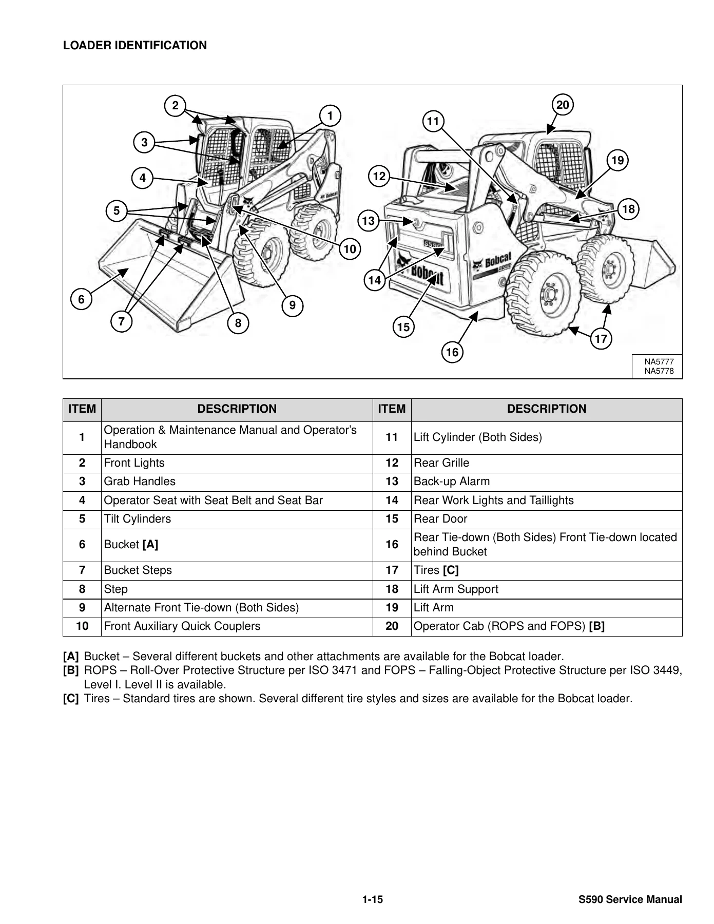
LOADER IDENTIFICATIONp. 17
+SAFETY AND MAINTENANCEp. 19
+LIFTING AND BLOCKING THE LOADERp. 23
+LIFT ARM SUPPORTp. 25
Descriptionp. 25
Installingp. 26
Removingp. 27
+OPERATOR CABp. 29
Descriptionp. 29
Cab Door Sensorp. 29
Raisingp. 30
Loweringp. 31
Special Applications Kitp. 32
Special Applications Kit Inspection And Maintenancep. 32
Forestry Door And Window Kitp. 33
Forestry Door And Window Kit Inspection And Maintenancep. 33
+TRANSPORTING THE LOADER ON A TRAILERp. 35
Loading And Unloadingp. 35
Fasteningp. 35
+TOWING THE LOADERp. 37
+REMOTE START TOOL KIT – MEL1563p. 39
Remote Start Tool – MEL1563p. 39
Service Tool Harness Communicator – MEL1566p. 41
Remote Start Procedurep. 41
+REMOTE START TOOL (SERVICE TOOL) KIT – 7217666p. 45
Descriptionp. 45
Remote Start Tool (Service Tool) – 7022042p. 46
Loader Service Tool Harness – 6689747p. 47
Computer Service Tool Harness – 6689746p. 48
Remote Start Procedurep. 49
+SERVICE SCHEDULEp. 53
Maintenance Intervalsp. 53
+ENGINE AIR CLEANERp. 55
+ENGINE COOLING SYSTEMp. 57
Maintenance Platformp. 57
Cleaningp. 57
Checking And Adding Coolantp. 60
Removing And Replacing Coolantp. 61
+FUEL SYSTEMp. 63
Fuel Specificationsp. 63
Biodiesel Blend Fuelp. 63
Filling The Fuel Tankp. 64
Fuel Filterp. 65
Replacing Fuel Pre-Filterp. 66
Replacing Main Fuel Filterp. 67
+ENGINE LUBRICATION SYSTEMp. 69
Checking And Adding Engine Oilp. 69
Engine Oil Chartp. 69
Removing And Replacing Oil And Filterp. 70
+HYDRAULIC / HYDROSTATIC SYSTEMp. 73
Checking And Adding Fluidp. 73
Hydraulic / Hydrostatic Fluid Chartp. 73
Removing And Replacing Hydraulic Fluidp. 74
Removing And Replacing Hydraulic / Hydrostatic Filterp. 76
Removing And Replacing Hydraulic Charge Filterp. 77
Replacing Reservoir Breather Capp. 78
+FINAL DRIVE TRANSMISSION (CHAINCASE)p. 79
Checking And Adding Fluidp. 79
Removing And Replacing Fluidp. 79
+BOB-TACH (HAND LEVER)p. 81
Inspection And Maintenancep. 81
+BOB-TACH (POWER)p. 83
Inspection And Maintenancep. 83
+LUBRICATING THE LOADERp. 85
Lubrication Locationsp. 85
+TIRE MAINTENANCEp. 89
Wheel Nutsp. 89
Rotatingp. 89
Mountingp. 90
+PIVOT PINSp. 91
Inspection And Maintenancep. 91
+LOADER STORAGE AND RETURN TO SERVICEp. 93
Storagep. 93
Return To Servicep. 93
+STOPPING THE ENGINE AND LEAVING THE LOADERp. 95
+EMERGENCY EXITp. 97
Rear Window Identificationp. 97
Rear Window Removal (Latches)p. 97
Rear Window Removal (Rubber Cord)p. 97
External Access (Rear Window With Latches)p. 98
External Access (Rear Window With Rubber Cord)p. 98
Front Doorp. 99
+SEAT BELTp. 101
Inspection And Maintenancep. 101
+HYDRAULIC SYSTEMp. 103
HYDRAULIC / HYDROSTATIC SCHEMATICSp. 107
+HYDRAULIC SYSTEM INFORMATIONp. 115
Glossary Of Hydraulic / Hydrostatic Symbolsp. 115
Troubleshootingp. 119
+CYLINDER (LIFT)p. 121
Testingp. 121
Removal And Installationp. 122
Parts Identificationp. 126
Disassemblyp. 127
Assemblyp. 129
+CYLINDER (TILT)p. 133
Testingp. 133
Removal And Installationp. 134
Base End Pivot Pin Removal And Installationp. 135
Parts Identificationp. 136
Disassemblyp. 137
Assemblyp. 139
+CYLINDER (BOB-TACH)p. 143
Testingp. 143
Removal And Installationp. 144
Parts Identificationp. 145
Disassemblyp. 146
Assemblyp. 148
+MAIN RELIEF VALVEp. 151
Descriptionp. 151
Testingp. 152
Adjustingp. 154
Removal And Installationp. 155
+HYDRAULIC CONTROL VALVE (STANDARD)p. 157
Descriptionp. 157
Removal And Installationp. 158
Mount Bracket Removal And Installationp. 161
Identification Chartp. 162
Lift Load Check Valve Removal And Installationp. 163
Load Check Valve Removal And Installation (Tilt And Auxiliary)p. 164
Anti-Cavitation Valve Removal And Installation (Lift, Rod End)p. 165
Port Relief / Anti-Cavitation Valve Removal And Installation (Lift, Base End)p. 165
Port Relief / Anti-Cavitation Valve Removal And Installation (Tilt, Base End)p. 166
Port Relief / Anti-Cavitation Valve Removal And Installation (Tilt, Rod End)p. 166
Port Relief Valve Removal And Installationp. 167
Plug Removal And Installationp. 169
Rubber Boot Removal And Installationp. 170
End Cap Block Removal And Installationp. 170
Lift Spool And Detent Removal And Installationp. 171
Tilt Spool Removal And Installationp. 179
Auxiliary Spool Removal And Installationp. 181
Auxiliary Solenoid Removal And Installationp. 182
Solenoid Removal And Installationp. 183
Lock Valve Removal And Installationp. 184
Lift Arm Bypass Orifice Removal And Installationp. 186
Main Relief Valve Removal And Installationp. 186
Check Valve Removal And Installationp. 187
+HYDRAULIC CONTROL VALVE (SJC)p. 189
Descriptionp. 189
Removal And Installationp. 189
Actuator Removal And Installation (In Loader)p. 193
Actuator Removal And Installation (Out Of Loader)p. 195
Identification Chartp. 198
Mount Bracket Removal And Installationp. 199
Lift Load Check Valve Removal And Installationp. 199
Load Check Valve Removal And Installation (Tilt And Auxiliary)p. 200
Anti-Cavitation Valve Removal And Installation (Lift, Rod End)p. 201
Port Relief / Anti-Cavitation Valve Removal And Installation (Lift, Base End)p. 201
Port Relief / Anti-Cavitation Valve Removal And Installation (Tilt, Base End)p. 202
Port Relief / Anti-Cavitation Valve Removal And Installation (Tilt, Rod End)p. 202
Port Relief Valve Removal And Installationp. 203
Plug Removal And Installationp. 205
End Cap Block Removal And Installationp. 206
Lift Spool Removal And Installationp. 206
Lift Spool Disassembly And Assemblyp. 208
Tilt Spool Removal And Installationp. 209
Auxiliary Spool Removal And Installationp. 211
Auxiliary Solenoid Removal And Installationp. 212
Solenoid Removal And Installationp. 213
Lock Valve Removal And Installationp. 214
Lift Arm Bypass Orifice Removal And Installationp. 216
Main Relief Valve Removal And Installationp. 216
Check Valve Removal And Installationp. 217
+LIFT ARM BYPASS CONTROL VALVEp. 219
Descriptionp. 219
Testingp. 219
Removal And Installationp. 220
Bracket Removal And Installationp. 221
Disassembly And Assemblyp. 221
+HYDRAULIC PUMPp. 223
Descriptionp. 223
Pump Test At Quick Couplersp. 224
Direct Pump Test (Standard Section)p. 226
Direct Pump Test (Charge Section)p. 228
Removal And Installationp. 230
Hydraulic Pump Startupp. 232
Parts Identificationp. 233
Disassembly And Assemblyp. 234
+HYDRAULIC PUMP (HIGH FLOW)p. 235
Descriptionp. 235
Pump Test At Quick Couplersp. 236
Direct Pump Test (Standard Section)p. 238
Direct Pump Test (Charge Section)p. 239
Direct Pump Test (High Flow Section)p. 241
High Flow Relief Valve Adjustmentp. 243
High Flow Relief Valve Removal And Installationp. 245
Solenoid Removal And Installationp. 246
Removal And Installationp. 247
Hydraulic Pump Startupp. 249
Parts Identificationp. 250
Disassembly And Assemblyp. 251
+HYDRAULIC / HYDROSTATIC FILTERSp. 253
Descriptionp. 253
Housing Removal And Installationp. 253
+HYDRAULIC FLUID RESERVOIRp. 255
Descriptionp. 255
Removal And Installationp. 255
Hydraulic Fluid Screenp. 256
+OIL COOLERp. 257
Removal And Installationp. 257
+BUCKET POSITION VALVEp. 259
Descriptionp. 259
Removal And Installationp. 259
Solenoid Testingp. 260
Disassembly And Assemblyp. 261
+REAR AUXILIARY DIVERTER VALVEp. 263
Descriptionp. 263
Solenoid Testingp. 263
Removal And Installationp. 264
Disassembly And Assemblyp. 265
+BOB-TACH (POWER) BLOCKp. 271
Descriptionp. 271
Testing Relief Valvep. 272
Removal And Installationp. 274
Disassembly And Assemblyp. 276
+FRONT AUXILIARY HYDRAULIC COUPLER BLOCKp. 281
Descriptionp. 281
Removal And Installationp. 281
Disassembly And Assemblyp. 281
+AUTOMATIC RIDE CONTROLp. 285
Descriptionp. 285
Removal And Installationp. 285
Checking The Pressure In The Accumulatorp. 287
Adding Nitrogen To The Accumulatorp. 289
+HYDROSTATIC SYSTEMp. 291
+HYDROSTATIC SYSTEM INFORMATIONp. 293
Descriptionp. 293
Troubleshootingp. 294
+HYDROSTATIC DRIVE MOTORp. 295
Descriptionp. 295
Removal And Installationp. 295
Parts Identificationp. 298
Disassembly And Assemblyp. 299
+HYDROSTATIC DRIVE MOTOR (TWO-SPEED)p. 305
Descriptionp. 305
Removal And Installation (Left Side)p. 306
Removal And Installation (Right Side)p. 309
Parts Identificationp. 312
Disassemblyp. 313
Assemblyp. 326
+HYDROSTATIC MOTOR CARRIERp. 341
Descriptionp. 341
Shaft Seal Removal And Installationp. 342
Removal And Installationp. 344
Parts Identificationp. 346
Disassemblyp. 347
Assemblyp. 349
+HYDROSTATIC MOTOR CARRIER (TWO-SPEED)p. 353
Descriptionp. 353
Shaft Seal Removal And Installationp. 354
Removal And Installationp. 356
Parts Identificationp. 358
Disassemblyp. 359
Assemblyp. 361
+CHARGE PRESSUREp. 365
Descriptionp. 365
Testingp. 366
Adjustingp. 368
Sender Removal And Installation (Earlier Models)p. 370
Sender Removal And Installation (Later Models)p. 370
+HYDROSTATIC PUMPp. 371
Descriptionp. 371
Removal And Installationp. 372
Hydrostatic Pump Startupp. 373
Replenishing / High Pressure Relief Valve Removal And Installationp. 374
Parts Identification (Left Half)p. 375
Parts Identification (Right Half)p. 376
Disassemblyp. 377
Assemblyp. 384
+HYDROSTATIC PUMP (SJC)p. 391
Descriptionp. 391
Port Locations And Gauge Installationp. 392
Removal And Installationp. 393
Hydrostatic Pump Startupp. 395
Parts Identificationp. 396
High Pressure Relief And Bypass Valvep. 399
Charge Pressure Relief Valvep. 400
Disassembly And Assemblyp. 401
Mechanical Neutral Adjustmentp. 413
Hydraulic Controller Neutral Adjustmentp. 415
+DRIVE BELTp. 417
Belt Adjustmentp. 417
Stop Adjustmentp. 417
Belt Replacementp. 418
Tensioner Pulley Removal And Installation (Earlier Models)p. 420
Tensioner Pulley Disassembly And Assemblyp. 420
Tensioner Pulley Removal And Installation (Later Models)p. 421
Tensioner Pulley Disassembly And Assemblyp. 421
+TWO-SPEEDp. 423
Valve Block Removal And Installationp. 423
Valve Block Disassembly And Assemblyp. 424
+DRAIN MANIFOLDp. 425
Descriptionp. 425
Drain Manifold Removal And Installationp. 425
+DRIVE SYSTEMp. 427
+BRAKEp. 429
Descriptionp. 429
Disc Removal And Installationp. 429
+DRIVE COMPONENTSp. 431
Descriptionp. 431
Axle Seal Removal And Installationp. 432
Axle, Sprocket And Bearings Removal And Installationp. 434
Chain Removal And Installationp. 439
+CHAINCASEp. 441
Descriptionp. 441
Front Cover Removal And Installationp. 441
Center Cover Removal And Installationp. 442
Rear Cover Removal And Installationp. 443
+MAINFRAMEp. 445
+SEAT BARp. 449
Descriptionp. 449
Removal And Installationp. 449
Disassembly And Assemblyp. 450
Compression Spring Disassembly And Assemblyp. 451
+OPERATOR CABp. 453
Gas Spring Removal And Installationp. 453
Gas Spring Bracket Disassembly And Assemblyp. 454
Removal And Installationp. 454
+OPERATOR SEATp. 457
Removal And Installationp. 457
Seat Belt Removal And Installation (Retractable)p. 457
Seat Belt And Bracket Removal And Installation (Standard)p. 458
Seat Belt Bracket Removal And Installationp. 458
+OPERATOR SEAT (SUSPENSION)p. 459
Removal And Installationp. 459
Slide Rail Removal And Installationp. 459
Seat Belt Removal And Installationp. 460
Lower Cushion Removalp. 460
Lower Cushion Installationp. 461
Back Cushion Removal And Installationp. 461
Shock Removal And Installationp. 462
3-Point Seat Belt Removal And Installationp. 462
+BOB-TACH (HAND LEVER)p. 465
Descriptionp. 465
Removal And Installationp. 465
Lever And Wedge Disassembly And Assemblyp. 468
Pivot Pin Bushing And Seal Removal And Installationp. 470
+BOB-TACH (POWER)p. 471
Descriptionp. 471
Removal And Installationp. 471
Lever And Wedge Disassembly And Assemblyp. 474
Pivot Pin Bushing And Seal Removal And Installationp. 476
+LIFT ARMSp. 477
Stabilizer Bar Removal And Installationp. 477
Link Removal And Installationp. 478
Removal And Installationp. 479
+REAR GRILLEp. 483
Removingp. 483
Installingp. 483
Shield Removal And Installationp. 484
+REAR DOOR (TAILGATE)p. 485
Removal And Installationp. 485
Striker Removal And Installationp. 486
Striker Disassembly And Assemblyp. 486
Striker Adjustingp. 487
Latch Removal And Installationp. 488
+FUEL TANKp. 489
Removal And Installationp. 489
Fuel Level Sender Removal And Installationp. 491
Fuel Fill Screen Removal And Installationp. 491
+CONTROL PEDALS AND LINKAGESp. 493
Descriptionp. 493
Pedal Removal And Installationp. 493
Linkage Removal And Installationp. 494
Pedal (Adjusting)p. 495
Floor Pan Removal And Installationp. 496
+CONTROL PANELp. 497
Descriptionp. 497
Removal And Installationp. 498
Disassembly And Assemblyp. 499
Linkage Removal And Installationp. 504
Pintle Arm Disassembly And Assemblyp. 507
Linkage Neutral (Adjusting)p. 508
Linkage Travel (Adjusting)p. 512
Shock Removal And Installationp. 516
+CONTROL PANEL (SJC)p. 517
Descriptionp. 517
Removal And Installationp. 517
+CONTROL HANDLE / LEVERp. 519
Descriptionp. 519
Lever Removal And Installationp. 519
Boot Removal And Installationp. 520
+CONTROL HANDLE / LEVER (SJC)p. 521
Descriptionp. 521
Joystick Testingp. 521
Joystick Removal And Installationp. 522
+ACCESS PANEL (INSIDE)p. 523
Removal And Installation (Left)p. 523
Removal And Installation (Right)p. 523
+ACCESS PANEL (INSIDE) (SJC)p. 525
Removal And Installation (Left)p. 525
Removal And Installation (Right)p. 525
+WINDOW (REAR)p. 527
Rear Window Identificationp. 527
Rear Window Removal (Latches)p. 527
Rear Window Removal (Rubber Cord)p. 527
External Access (Rear Window With Latches)p. 528
External Access (Rear Window With Rubber Cord)p. 528
Disassembly And Assembly (Latches)p. 529
+WINDOW (TOP)p. 531
Removal And Installationp. 531
+WINDOW (SIDE)p. 533
Removal And Installationp. 533
+CAB DOORp. 535
Descriptionp. 535
Removal And Installationp. 535
Disassembly And Assemblyp. 536
Aligningp. 537
Adjustingp. 538
Checking Operationp. 538
+ARMRESTp. 539
Descriptionp. 539
Removal And Installationp. 540
Disassembly And Assemblyp. 541
+LEFT SIDE LOWER PANELp. 543
Removal And Installationp. 543
Disassembly And Assemblyp. 546
+RIGHT SIDE LOWER PANELp. 547
Removal And Installationp. 547
Disassembly And Assemblyp. 549
+HEADLINERp. 551
Removal And Installationp. 551
+FAN DUCT PANELSp. 553
Removal And Installationp. 553
+ELECTRICAL SYSTEMp. 555
ELECTRICAL SCHEMATICSp. 559
+ELECTRICAL SYSTEM INFORMATIONp. 592
Glossary Of Electrical Symbolsp. 592
Standard Cab Harness Connectorsp. 595
Deluxe Cab Harness Connectorsp. 596
Mainframe Harness Connectorsp. 597
Descriptionp. 598
Troubleshootingp. 599
Fuse And Relay Location / Identificationp. 600
Solenoid Testingp. 603
+BATTERYp. 604
Removal And Installationp. 604
Battery Maintenancep. 605
Maintaining Battery Charge Levelp. 605
Battery Service During Machine Storagep. 605
Battery Testingp. 606
Battery Chargingp. 606
Using A Booster Battery (Jump Starting)p. 607
+ALTERNATORp. 608
Belt Adjustmentp. 608
Belt Replacementp. 608
Charging System Inspectionp. 609
Alternator Voltage Testingp. 610
Low Voltage Testingp. 610
High Voltage Testingp. 611
Removal And Installationp. 612
Parts Identificationp. 614
+STARTERp. 616
Testingp. 616
Removal And Installationp. 616
Parts Identificationp. 617
+INSTRUMENT PANEL IDENTIFICATIONp. 618
Overviewp. 618
Left Panelp. 619
Display Screenp. 621
Right Panelp. 622
Left Switch Panelp. 624
Right Switch Panelp. 624
Left Side Lower Panelp. 625
Right Side Lower Panelp. 625
Left Panel Removal And Installationp. 626
Right Panel Removal And Installationp. 626
Key Switch Disassembly And Assemblyp. 627
Alarm Disassembly And Assemblyp. 627
Left Switch Panel Removal And Installationp. 628
Right Switch Panel Removal And Installationp. 628
+LIGHTSp. 630
Front Removal And Installationp. 630
Rear Removal And Installationp. 631
Cab Light Removal And Installationp. 631
+BOBCAT CONTROLLERS (GATEWAY AND AUXILIARY)p. 632
Descriptionp. 632
Connector Identificationp. 633
Removal And Installationp. 639
+BOBCAT CONTROLLER (SJC) (DRIVE)p. 640
Descriptionp. 640
Connector Identificationp. 641
Removal And Installationp. 643
+ENGINE CONTROL UNIT (ECU)p. 644
Descriptionp. 644
Cleaningp. 645
Removal And Installationp. 646
+DIAGNOSTIC SERVICE CODESp. 648
Viewing Service Codesp. 648
Service Codes Listp. 649
+BOBCAT INTERLOCK CONTROL SYSTEM (BICS™)p. 664
Descriptionp. 664
Inspecting The BICS™ (Engine STOPPED – Key ON)p. 665
Inspecting Deactivation Of The Auxiliary Hydraulics System (Engine STOPPED – Key ON)p. 665
Inspecting The Seat Bar Sensor (Engine RUNNING)p. 665
Inspecting The Traction Lock And Parking Brake (Engine RUNNING)p. 665
Inspecting The Lift Arm Bypass Controlp. 665
Inspecting Deactivation Of Lift And Tilt Functions (ACS And SJC)p. 665
Troubleshootingp. 666
+SEAT BAR SENSORp. 668
Descriptionp. 668
Troubleshootingp. 668
Testingp. 669
Removalp. 670
Installationp. 672
Bobcat Interlock Control System (BICS™) Circuit Testp. 673
+TRACTION LOCKp. 676
Descriptionp. 676
Troubleshootingp. 677
Inspectingp. 678
+ELECTRICAL / HYDRAULIC CONTROLS (MANUAL)p. 680
Identification Chartp. 680
Descriptionp. 681
Identification Chart ACD Group 0p. 682
Identification Chart ACD Group 1p. 683
Identification Chart ACD Group 2p. 684
Identification Chart ACD Group 3p. 685
+ELECTRICAL / HYDRAULIC CONTROLS (SJC)p. 686
Identification Chartp. 686
Descriptionp. 687
Identification Chart ACD Group 0p. 688
Identification Chart ACD Group 1p. 689
Identification Chart ACD Group 2p. 690
Identification Chart ACD Group 3p. 691
+SERVICE PC (LAPTOP COMPUTER)p. 692
Connecting Remote Start Tool (Service Tool)p. 692
+CALIBRATIONp. 694
Descriptionp. 694
Actuator Testingp. 694
Lift And Tilt Calibration (SJC)p. 697
Hydrostatic Pump Calibration (SJC)p. 699
+STEERING DRIFT COMPENSATION (OPERATOR MODE)p. 704
Descriptionp. 704
Operationp. 704
+STEERING DRIFT COMPENSATION (SERVICE MODE)p. 706
Descriptionp. 706
Operationp. 706
+CONTROL PANEL SETUPp. 708
Right Panel Setup (Deluxe Instrumentation Panel)p. 708
+PASSWORD SETUP (DELUXE INSTRUMENTATION PANEL)p. 712
Password Descriptionp. 712
Changing The Owner Passwordp. 712
Changing The User Passwordsp. 713
Password Lockout Featurep. 713
+MAINTENANCE CLOCKp. 714
Descriptionp. 714
Setupp. 715
Resetp. 715
+BACK-UP ALARM SYSTEMp. 716
Descriptionp. 716
Inspectingp. 716
Adjusting Switch Positionp. 717
Troubleshooting (Standard)p. 718
Troubleshooting (Joystick)p. 719
Alarm Removal And Installationp. 720
Switch Removal And Installationp. 720
+FRONT HORNp. 722
Removal And Installationp. 722
Troubleshootingp. 723
Troubleshooting (Joystick)p. 724
+ENGINE SPEED CONTROL (HAND)p. 726
Removal And Installationp. 726
+ENGINE SPEED CONTROL (FOOT)p. 728
Removal And Installationp. 728
Disassembly And Assemblyp. 729
Foot Throttle Calibrationp. 731
+CAMSHAFT AND CRANKSHAFT POSITION SENSORp. 734
Removal And Installationp. 734
+MACHINE IQp. 736
Descriptionp. 736
Removal And Installationp. 736
Procedurep. 737
+ENGINE SERVICEp. 738
+ENGINE INFORMATIONp. 742
Descriptionp. 742
Specificationsp. 743
Sensor Locationp. 745
Torque Valuesp. 750
Troubleshootingp. 752
Engine Removal And Installationp. 754
Engine Mount Replacementp. 762
Compression – Testingp. 764
Injector Signal – Testingp. 766
Injector Signal – Testing (In-Line)p. 768
+DIESEL PARTICULATE FILTER (DPF) SYSTEMp. 770
Descriptionp. 770
Removal And Installationp. 770
DPF Iconsp. 771
DPF Regeneration Tablesp. 772
Automatic Regeneration Operationp. 773
Forced Regeneration Operationp. 774
Forced Parked Regeneration Operationp. 775
Inhibit Mode Operationp. 776
+AIR CLEANERp. 778
Housing Removal And Installationp. 778
+ENGINE COOLING SYSTEMp. 780
Radiator / Oil Cooler Removal And Installationp. 780
Hydraulic Fan Descriptionp. 782
Reversible Hydraulic Fan Descriptionp. 783
Fan Duct Removal And Installationp. 783
Hydraulic Fan Motor Assembly Removal And Installationp. 784
Hydraulic Fan Motor Removal And Installationp. 785
Hydraulic Fan Motor Disassembly And Assemblyp. 787
Blower Housing Removal And Installationp. 795
Water Pump Removal And Installationp. 796
Thermostat Housing Removal And Installationp. 797
Testing The Thermostatp. 798
+LUBRICATION SYSTEMp. 800
Descriptionp. 800
Oil Pan Removal And Installationp. 801
Oil Pump Removal And Installationp. 802
Oil Pump Relief Valve Descriptionp. 803
Oil Pump Relief Valve Removal And Installationp. 803
Oil Cooler Removal And Installationp. 804
Oil Filter Head Removal And Installationp. 805
Oil Cooler Bypass Descriptionp. 806
Oil Cooler Bypass Removal And Installationp. 806
+FUEL SYSTEMp. 808
Descriptionp. 808
Fuel Filter Housing Removal And Installationp. 809
Fuel Lift Pump Removal And Installationp. 811
Transfer Pump / High Pressure Pump Removal And Installationp. 811
Fuel Temperature Sensor Removal And Installationp. 813
Fuel Cooler Removal And Installationp. 814
Fuel Recirculation Valve (FRV) Removal And Installationp. 814
Fuel Injector Removal And Installationp. 815
Injector Codingp. 817
+CYLINDER HEADp. 818
Glow Plugs Testingp. 818
Glow Plug Removal And Installationp. 819
Cylinder Head Removal And Installationp. 820
Cylinder Head Disassembly And Assemblyp. 825
Cylinder Head Inspectionp. 826
Cylinder Head Top Clearancep. 827
Valve Step Heightp. 828
Valve Stem Heightp. 828
Valve Guidep. 829
Valvep. 829
Valve Springp. 830
Rocker Arm Shaft Disassembly And Assemblyp. 831
Rocker Arm Shaft Inspectionp. 832
Push Rod Inspectionp. 832
+CRANKSHAFT AND PISTONSp. 834
Piston And Connecting Rod Removal And Installationp. 834
Piston And Connecting Rod Inspectionp. 835
Crankshaft Removal And Installationp. 837
Cylinder Block Inspectionp. 840
Crankshaft Inspectionp. 842
Connecting Rod Inspectionp. 842
Engine Component Classp. 843
+CAMSHAFTp. 846
Removal And Installationp. 846
Inspectingp. 847
+GEARCASEp. 850
Gearcase Cover Removal And Installationp. 850
Gear Backlashp. 851
Gear Timingp. 852
Idle Gear Removal And Installationp. 853
Idle Gear Inspectionp. 853
+TURBOCHARGERp. 854
Descriptionp. 854
Removal And Installationp. 854
Inspectionp. 857
+FLYWHEEL AND HOUSINGp. 858
Flywheel Removal And Installationp. 858
Ring Gear Removal And Installationp. 859
Housing Removal And Installationp. 859
+EXHAUST GAS RECIRCULATION (EGR) SYSTEMp. 860
Descriptionp. 860
Removal And Installationp. 861
+HEATING, VENTILATION AND AIR CONDITIONING (HVAC)p. 864
+AIR CONDITIONING SYSTEM FLOWp. 866
Descriptionp. 866
Chartp. 867
Componentsp. 868
Safety Equipmentp. 871
+REGULAR MAINTENANCEp. 872
Filtersp. 872
Belt Adjustmentp. 873
Belt Replacementp. 873
Air Conditioning Condenserp. 873
Air Conditioning Lubricationp. 873
Air Conditioning Service Chartp. 874
Evaporator / Heater Coilp. 875
+TROUBLESHOOTINGp. 878
Blower Motor Does Not Operatep. 878
Blower Motor Operates Normally, But Air Flow Is Insufficientp. 878
Insufficient Cooling Although Air Flow And Compressor Operation Are Normalp. 878
The Compressor Does Not Operate At All, Or Operates Improperlyp. 878
Gauge Pressure Related Troubleshootingp. 879
Troubleshooting Treep. 881
Temperature / Pressure Chartp. 885
Poor A/C Performancep. 887
HVAC Repair And Leaksp. 888
Electrical Systemp. 889
Engine Coolant Bypassing The Heater Valvep. 895
Heater Valve Not Opening Or Closingp. 896
+SYSTEM CHARGING AND RECLAMATIONp. 898
Refrigerant Identificationp. 898
Reclamation And Charging With Recovery / Charging Unitp. 899
+COMPRESSORp. 902
Removal And Installationp. 902
Oilp. 904
Oil Checkp. 905
+CONDENSERp. 908
Removal And Installationp. 908
+RECEIVER / DRIERp. 910
Receiver / Drier Removal And Installationp. 910
Pressure Switch Removal And Installationp. 912
Schrader® Valve Removal And Installationp. 913
+EVAPORATOR / HEATER UNITp. 914
Removal And Installationp. 914
+THERMOSTATp. 916
Descriptionp. 916
Removal And Installationp. 917
+EXPANSION VALVEp. 918
Removal And Installationp. 918
+EVAPORATOR COILp. 920
Removal And Installationp. 920
+HEATER COILp. 922
Removal And Installationp. 922
+BLOWER FANp. 924
Removal And Installationp. 924
Disassembly And Assemblyp. 924
+HEATER VALVEp. 928
Removal And Installationp. 928
+EVAPORATOR / HEATER COVERp. 930
Removingp. 930
Installingp. 930
+SPECIFICATIONSp. 932
+(S590) LOADER SPECIFICATIONSp. 934
Machine Dimensionsp. 934
Performancep. 935
Enginep. 935
Drive Systemp. 936
Controlsp. 936
Hydraulic Systemp. 937
Electrical Systemp. 938
Capacitiesp. 938
Tiresp. 939
Environmentalp. 939
Temperature Rangep. 939
+TECHINCAL SERVICE GUIDE SPECIFICATIONSp. 940
Enginep. 940
Engine Torquesp. 940
Cooling Systemp. 940
Loader Torquesp. 941
Hydraulic / Hydrostatic Systemp. 941
Fuel Consumptionp. 941
+TORQUE SPECIFICATIONS FOR BOLTSp. 942
Torque For General SAE Boltsp. 942
Torque For General Metric Boltsp. 943
+HYDRAULIC CONNECTION SPECIFICATIONSp. 944
Straight Thread O-ring Fittingp. 944
Flare Fittingp. 945
Tubelines And Hosesp. 945
+HYDRAULIC / HYDROSTATIC FLUID SPECIFICATIONSp. 946
+CONVERSIONSp. 948
Decimal And Millimeter Equivalent Chartp. 948
U.S. To Metric Conversion Chartp. 948
+SERVICE TOOLS REQUIREDp. 950
Remote Start Toolsp. 950
Hydraulic Toolsp. 951
Mainframe And Drive Toolsp. 954
Electrical Toolsp. 957
Engine Toolsp. 958
HVAC Toolsp. 963
ALPHABETICAL INDEXp. 964
Electrical, Controllers and Diagnostics
The electrical system is documented in unusual depth. A symbol glossary and harness connector maps for the standard cab, deluxe cab and mainframe harnesses precede the fuse and relay identification for both standard and SJC machines. Individual component chapters cover the battery, alternator with voltage and low/high voltage testing, and starter testing. The controller chapters cover the Gateway, Auxiliary, SJC Drive and Engine Control Unit with pin-by-pin connector identification, plus the Bobcat Interlock Control System inspection sequence, seat bar sensor testing with the sensor tester, and the traction lock. A full diagnostic service code list runs through the letter codes and the numeric codes, with the code descriptions for the drive, hydraulic, engine, auxiliary and ACD systems. Calibration procedures for the lift and tilt actuators and the hydrostatic pump are given in step-by-step form, as are the operator and service mode steering drift compensation procedures.
Cab, Mainframe and Operator Station
The mainframe section handles the structural and operator-side work: seat bar removal and compression spring assembly, operator cab gas springs and cab removal, operator and suspension seat service, seat belt replacement, hand lever and power Bob-Tach service including lever, wedge, pivot pin bushing and seal work, lift arm and stabilizer bar removal, rear grille, rear door and striker adjustment, fuel tank removal, control pedals and linkage adjustment, control panel and SJC control panel removal, control handle and joystick service, access panels, rear and side windows, cab door alignment and adjustment, armrest, lower panels, headliner and fan duct panels.
HVAC and Optional Equipment
For machines fitted with air conditioning, the HVAC chapters cover the refrigerant flow path, regular maintenance including fresh air and recirculation filters and the air conditioning belt, troubleshooting by symptom and by gauge pressure, evacuation and recharging, compressor service and oil check, condenser, receiver/drier and pressure switch, evaporator/heater unit, thermostat, expansion valve, evaporator coil, heater coil, blower fan and heater valve. Optional equipment covered elsewhere in the manual includes the two-speed drive, high flow hydraulics, automatic ride control, bucket positioning, reversing fan, rear auxiliary diverter valve and Power Bob-Tach.
Why the Bobcat S590 Skid-Steer Loader Service Manual Matters
Skid-steer loaders are compact, heavily loaded machines, and the S590 is no exception. Torque values that are guessed, seal orientations that are reversed, charge pressures that are set by feel and hydrostatic neutral adjustments that are skipped all show up later as failed pumps, drifting travel and premature component wear. Having the correct procedure, the correct specification and the correct sequence in front of you removes that guesswork. The manual also carries the diagnostic service code list, which turns an instrument panel warning into a defined starting point instead of a search, and the wiring schematics, which make tracing an intermittent electrical fault a matter of following a circuit rather than pulling the harness apart.
Get the Bobcat S590 Service Manual Delivered Instantly
With the Bobcat S590 Skid-Steer Loader Service Manual on hand you can service the engine and emissions system, rebuild lift and tilt cylinders, test and adjust the hydraulic pump, service the hydrostatic pump and motors, replace drive chains and axle bearings, diagnose controller and sensor faults, calibrate the lift, tilt and hydrostatic systems, and maintain the HVAC package. Correct procedures and correct specifications are what separate a repair that lasts from one that comes back. The file is delivered as an instant PDF download after payment, with no shipping and no waiting, and it can be read on a laptop, tablet or phone in the workshop or printed for the bench.

Reviews
There are no reviews yet.