Description
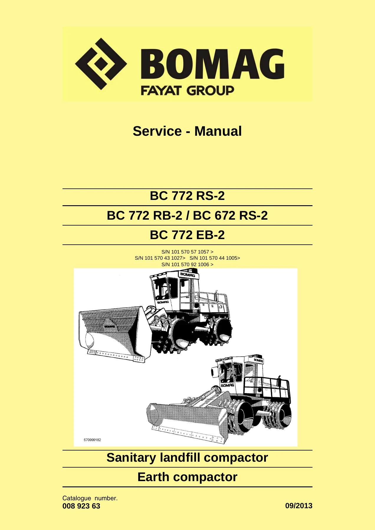
BOMAG BC 772 RB-2 Earth Compactor Service Manual
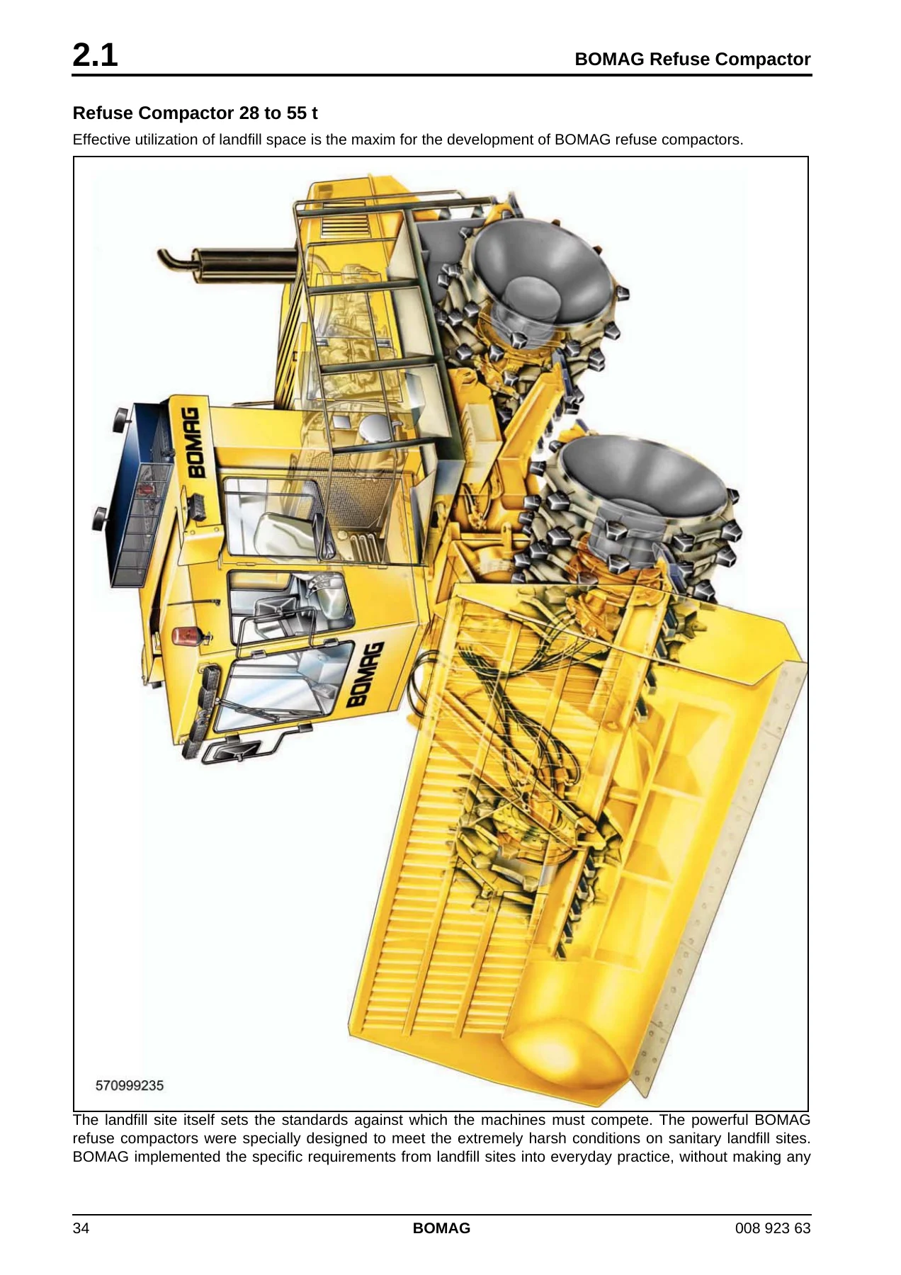
This is the full BOMAG service manual for the BC 772 RB-2 earth compactor and sanitary landfill compactor, catalogue number 008 923 63, dated 09/2013. The same document covers the BC 772 RS-2, BC 672 RS-2 and BC 772 EB-2 variants, so a single download serves the whole refuse compactor and soil compactor family built on this platform. It is written for the qualified technician or BOMAG after-sales personnel carrying out disassembly, repair, assembly, adjustment and fault diagnosis.
File Details
- Manual type: Service Manual (repair and maintenance)
- Brand: BOMAG (Fayat Group)
- Models covered: BC 772 RS-2, BC 772 RB-2, BC 672 RS-2, BC 772 EB-2
- Catalogue number: 008 923 63
- Edition/date: 09/2013
- Language: English
- Page count: 694 pages
- File format: PDF
Chapters Covered
- 1 General – Introduction, safety regulations, general repair instructions, tightening torques
- 2 Earth compactor / refuse compactor – BOMAG refuse compactor, BOMAG soil compactor
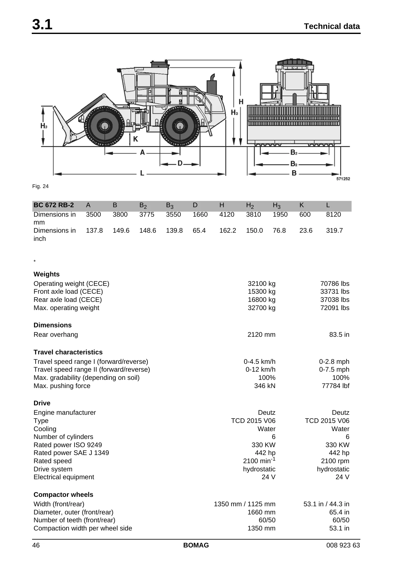
- 3 Technical data
- 4 Maintenance – general notes, fuels and lubricants, running-in instructions, maintenance table
- 5 Electrics – battery service and main battery switch, jump starting, main fuse, hydraulic oil temperature, pressure switches, magnetic sensor, level sensor in diesel tank, blower monitoring module A53, cab electrics, fuses, voltage supply checks for the control unit, diagnostics concept
- 6 Electronic control – ESX control, display module, code entry, parameter settings, fault codes, input codes, terminology
- 7 Engine electrics – engine control unit, pin assignment, system faults per flashing code, flashing code, diagnostics with SERDIA, diagnostics with CAN-bus, diagnostics interface, EMR3 list of fault codes, sensors
- 8 Engine – Deutz TCD 2015 V6 description, lubrication oil circuit, coolant circuit, fuel circuit, injection system (MVS), exhaust gas recirculation, wastegate charge pressure control, valve clearance, oil and filter changes, coolant, V-belts, engine mounts, crankcase pressure, troubleshooting chart, special tools
- 9 Automatic belt tensioner – removal, preassembly and installation (Deutz 2015 V6 & V8)
- 10 Hydraulics – hydraulic circuit, travel pumps A4VG85 DA and A4VG85 HT, steering and working pump, axial piston swash plate principle, travel motors A6VM 170EP, external gear pumps, travel system, towing, cooling, working hydraulics, control valve block, tests and adjustments, oil and filter changes
- 11 Automatic air conditioning – physical basics, refrigerant R134a, compressor oil, monitoring devices, components, Climatronic control, compressor oil level, magnetic clutch, servicing, drying and evacuation, leak test, filling instructions, troubleshooting
- 12 Central lubrication system – system layout, technical description, control, lubrication process, progressive distributor, lubrication oil pump, faults and causes, fault-cause-remedy
- 13 Oscillating articulated joint – live ring removal and installation, repairing the joint, steering cylinders, condition checks
- 14 Compactor wheels and dozer blade – wheel caps, welding on new caps, scrapers and edge cutter adjustment, cutting plates
- 15 Suppliers documentation – steering/working pump, wheel drive
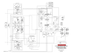
- 16 Circuit diagrams – hydraulic diagram EB/RB 571 908 15, hydraulic diagram RS 571 908 17, wiring diagram 254
Complete PDF Bookmark Tree
Complete Bookmarks
The complete bookmarks in the βBOMAG BC 772 RB-2 Earth Compactor Service Manual – BC 772 RS-2, BC 672 RS-2 & BC 772 EB-2 PDFβ are as follows:
BC 772 RS-2p. 1
BC 772 RB-2 / BC 672 RS-2p. 1
+BC 772 EB-2p. 1
S/N 101 570 57 1057 >p. 1
S/N 101 570 43 1027> S/N 101 570 44 1005>p. 1
S/N 101 570 92 1006 >p. 1
Sanitary landfill compactorp. 1
+Earth compactorp. 1
1.1 Introductionp. 8
+Safety regulationsp. 9
Important notesp. 9
Generalp. 9
Transport work with cranes and lifting tacklep. 9
Precautions and codes of conduct for welding workp. 9
Operation of high-voltage systemsp. 10
Old oilsp. 10
Hydraulicsp. 11
Fuelsp. 11
Hot fuelsp. 11
Synthetic rubberp. 11
Poisonous substancesp. 11
Enginep. 12
Air conditioning systemp. 12
Batteryp. 13
Special safety regulationsp. 13
+General repair instructionsp. 14
Generalp. 14
Electricsp. 14
Batteryp. 15
Generatorp. 16
Starter motorp. 16
Hydraulic systemp. 17
Air conditioning systemp. 18
+Notes on cleanliness for Common Rail enginesp. 19
+Fuel hosesp. 21
+Gaskets and mating surfacesp. 22
+Feather keys and keywaysp. 23
+Ball and roller bearingsp. 23
+Screws and nutsp. 24
Fig. 8 Identification of screwsp. 25
Fig. 9 Identification of nutsp. 25
Fig. 10 Identification of nuts in clock systemp. 26
Fig. 11p. 26
Fig. 12p. 27
+Tightening torquesp. 28
2 Earth compactor – refuse compactorp. 33
+BOMAG Refuse Compactorp. 34
Refuse Compactor 28 to 55 tp. 34
+Matured technologyp. 35
Fig. 13 The completely closed belly pan structure protects all drive components.p. 35
Fig. 14 Extended cleaning intervals by taking in cooling air at a height of 4 m.p. 36
Fig. 15 Oscillating articulated jointp. 36
+The dozer bladep. 36
Fig. 16 Refuse is distributed most efficiently with the wide dozer blade.p. 37
+The loading bucketp. 37
Fig. 17 The bucket makes the refuse compactor a universal toolp. 38
+The refuse compactor toolsp. 38
Fig. 18 Guaranteed tooth life of at least 10.000 operating with BOMAG PREMIUM composite casting teeth.p. 39
Fig. 19 Adjustable scrapers and BOMAG exchangeable caps preserve maximum compaction power over the entire life of the machine.p. 39
Fig. 20 Only polygonal disc wheels generate additional transverse forces to increase compaction and traction.p. 40
+BOMAG Soil Compactorp. 41
Soil Compactor 29 to 35 tp. 41
Distributing and compacting at the same timep. 41
+Robust overall conceptp. 41
Fig. 21 The completely closed belly pan structure protects all drive components.p. 41
+Best compaction and tractionp. 41
Fig. 22 Only polygonal disc wheels generate additional transverse forces to increase compaction and traction.p. 42
+Compaction conceptp. 42
Fig. 23 Soil compactor wheel with adjustable scrapers, which reliably prevent blockage of the wheels.p. 42
Full pushing powerp. 42
Highly effective drive systemp. 43
Safety and comfortp. 43
+Reliability and easy maintenancep. 43
+Technical datap. 46
Fig. 24p. 46
Fig. 25p. 48
Fig. 26p. 50
Fig. 27p. 52
Noise valuep. 56
+Vibration valuep. 56
+4.1 General notes on maintenancep. 58
Notes on the fuel systemp. 58
Notes on the performance of the enginep. 58
Notes on the cooling systemp. 58
Notes on the hydraulic systemp. 58
Welding work on the refuse compactorp. 59
+4.2 Fuels and lubricantsp. 59
+Engine oilp. 59
Fuelsp. 60
Coolantp. 60
Mineral oil based hydraulic oilp. 62
Bio-degradable hydraulic oilp. 62
Gear oilp. 62
Lubrication greasep. 62
4.3 Table of fuels and lubricantsp. 63
4.4 Running-in instructionsp. 65
+4.5 Maintenance tablep. 66
+5.1 Battery service, checking the main battery switchp. 70
Fig. 29p. 70
+Checking the main battery switchp. 70
+5.2 Starting the engine with jump leadsp. 71
+5.3 Main battery switchp. 72
+Fig. 32p. 72
No. 1 = Main battery switchp. 72
+5.4 Main fusep. 72
+5.5 Hydraulic oil temperaturep. 73
+Temperature sensor, R04p. 73
Fig. 34 Hydraulic oil tankp. 73
Fig. 35 Temperature display (z)p. 73
Fig. 36 Hydraulic oil tankp. 73
Fig. 37 Display module in central electricsp. 73
Fig. 38 Monitoring modulep. 74
+5.6 Pressure switch, hydraulic oil filterp. 74
+Differential pressure switches, B21, B22, B121, B122 and B42p. 74
Fig. 1p. 74
Fig. 2 Display module in central electricsp. 75
Fig. 3 Monitoring modulep. 75
Fig. 4p. 75
Fig. 5p. 75
Fig. 6 Monitoring modulep. 76
+5.7 Magnetic sensor, hydraulic oilp. 76
+Magnetic sensor, B19p. 76
Fig. 1p. 76
Fig. 2 Display module in central electricsp. 76
Fig. 3 Monitoring modulep. 77
+5.8 Pressure switch for brakep. 77
+Pressure switch, B05p. 77
Fig. 1p. 77
Fig. 2 Monitoring modulep. 77
+5.9 Level sensor in diesel tank (R03)p. 78
Fig. 1p. 78
+Fuel level gaugep. 78
Fig. 1 Fuel level gauge (j)p. 78
+5.10 Blower monitoring module A53p. 79
Fig. 1 Blower monitoring modulep. 79
Fig. 1p. 79
+Cab electrics
+5.12 Fusesp. 83
+5.13 Fuse, cabinp. 84
+Fig. 3p. 84
No. 2 = Fuse boxes, cabinp. 84
Machine related electrics
+5.15 Checking the voltage supply for the control unitp. 90
+Power supply for a control unit, generalp. 90
Fig. 4 Circuitry examplep. 90
Fig. 5 Circuitry examplep. 91
Fig. 6 Pinbox for 68 pole ESX controlp. 92
Fig. 7 Measuring arrangement 12 Voltp. 93
Fig. 8 Measuring arrangement 12 Voltp. 94
Fig. 9p. 95
Fig. 10p. 96
+5.16 Diagnostics conceptp. 98
+Introductionp. 98
(1) Fault memorized in error logp. 98
+(2) No fault memorized in the error log at the time of initial questioningp. 98
Fig. 12p. 99
+Fig. 13p. 100
6 Electronic controlp. 101
Bild 14p. 102
Bild 15p. 102
+6.1 ESX controlp. 103
Bild 16p. 104
+Bild 17p. 104
+7.1 Engine control unitp. 192
Fig. 18p. 192
Main relayp. 192
Replacing the control unitp. 193
7.2 Pin assignmentp. 194
+7.3 System faults per flashing codep. 200
+Engine protection function of the electric engine controllerp. 200
Fig. 19p. 200
Fig. 20p. 200
Deleting the error logp. 201
Flashing codep. 202
+7.5 Diagnose with SERDIAp. 204
+SERDIAp. 204
Fig. 1 Service-Software TCD 2012 / 2013p. 204
Fig. 2p. 205
Fig. 3p. 206
+7.6 Diagnose with CAN-busp. 207
+7.7 Diagnostics interfacep. 208
Fig. 1 Control unitp. 208
Fig. 2 Diagnostic interface in electric switchboxp. 208
Fig. 3 Diagnostic linkp. 208
Fig. 4p. 209
Fig. 5p. 209
Fig. 6p. 209
EMR3 List of fault codesp. 210
+7.9 Sensorsp. 281
Fig. 1p. 281
Fig. 2p. 282
Fig. 3p. 282
+7.10 Oil pressure sensorp. 283
+Pressure sensor, B88p. 283
Fig. 1p. 283
Fig. 2 Oil pressure sensorp. 283
Fig. 3p. 284
Fig. 4 Display module in central electricsp. 284
Fig. 5 Monitoring modulep. 284
Fig. 6p. 285
Fig. 7p. 285
Fig. 8p. 285
+Fuel temperature sensorp. 286
+Temperature senor, B126p. 286
+Charge air temperature – charge air pressure sensorp. 287
+Charge air temperature – charge air pressure sensor, B133p. 287
+Disassembling and assembling the sensorp. 288
Fig. 3p. 288
Fig. 4p. 288
Fig. 5p. 288
+7.13 EMR coolant temperature sensorp. 289
+Temperature sensor, B113p. 289
Fig. 1p. 289
Fig. 2p. 289
Fig. 3p. 290
Fig. 4 Display module in central electricsp. 290
Fig. 5 Monitoring modulep. 290
Fig. 6p. 291
Fig. 7p. 291
Fig. 8p. 291
Fig. 9p. 291
+Rotary speed sensor for crankshaftp. 292
+Rotary speed sensor, B130p. 292
+Rotary speed sensor for camshaftp. 293
+Rotary speed sensor, B114p. 293
+7.16 Preheating systemp. 294
+Glow plugs, R02p. 294
Fig. 1 Glow plug R02p. 294
Fig. 2 Solenoid valve Y02p. 294
Fig. 3p. 294
+Removing and installing the glow plugp. 294
Fig. 4p. 295
Fig. 5p. 295
Fig. 6p. 295
Fig. 7p. 295
Fig. 8p. 296
Fig. 9p. 296
Fig. 10p. 296
+7.17 Checking the preheating system.p. 297
Fig. 11p. 297
+Test step 1p. 297
+Test step 2p. 297
Test step 3p. 298
+7.18 Sensor, water in fuelp. 298
+Sensor, B124p. 298
Fig. 14p. 298
Fig. 15p. 298
Fig. 16p. 299
+7.19 Air filter vacuum switchp. 299
+Vacuum switches, B03 and B116p. 299
Fig. 17p. 299
Fig. 18 Display module in central electricsp. 300
Fig. 19 Monitoring modulep. 300
+7.20 Coolant temperature sensorp. 300
+Temperature sensor, B53p. 300
Fig. 20 Diesel enginep. 300
Fig. 21p. 300
+7.21 Float switch, coolant tankp. 301
+Float switch, B55p. 301
Fig. 1p. 301
Fig. 2 Display module in central electricsp. 301
Fig. 3 Monitoring modulep. 301
+7.22 Charge control light, engine RPM-meterp. 302
Fig. 1 Generatorp. 302
+Charge control lampp. 302
+Fig. 1 Monitoring modulep. 302
+8.1 Diesel enginep. 304
Fig. 1 Deutz diesel engine TCD 2015p. 304
+8.2 Engine description TCD 2015 V 6 cylinderp. 305
Fig. 1 Deutz diesel engine TCD 2015 V06 right hand sidep. 305
Fig. 2 Deutz diesel engine TCD 2015 V06 left hand sidep. 306
+8.3 Lubrication oil circuit TCD 2015p. 307
Fig. 1 Lubrication oil schematicp. 307
+8.4 Coolant circuit TCD 2015p. 308
Fig. 1 Coolant diagramp. 308
+8.5 Fuel circuit TCD 2015p. 309
Fig. 1 Fuel diagramp. 309
Fig. 2 Fuel pre-filterp. 310
Fig. 3 Fuel pre-filterp. 311
+8.6 Injection system (MVS) TCD 2015p. 312
Fig. 1 MVS – Injection system TCD 2015p. 312
Fig. 2 Electrics of TCD 2015p. 313
Fig. 3 Pump/solenoid valve TCD 2015p. 314
Fig. 4 Injection pump and nozzlep. 314
+8.7 Exhaust gas recirculation TCD 2015p. 315
Fig. 1 Exhaust valve control TCD 2015p. 315
+8.8 Wastegate – charge pressure controller on TCD-enginesp. 316
Fig. 1 Exhaust gas turbocharger with Wastegatep. 316
Fig. 2 Exhaust gas turbocharger with Wastegatep. 317
+8.9 Checking and adjusting the valve clearancep. 317
Fig. 3p. 318
Fig. 4p. 318
Fig. 5p. 318
Checking the valve clearancep. 318
+Adjusting the valve clearancep. 318
+8.10 Checking the engine oil levelp. 319
+8.11 Changing the engine oil and oil filterp. 319
Fig. 8p. 319
Fig. 9p. 320
Fig. 10p. 320
Fig. 11p. 320
+8.12 Replace the fuel filterp. 321
+Replace the fuel filter cartridges.p. 321
Fig. 12p. 321
Fig. 13p. 321
+Change the fuel pre-filter cartridgep. 321
+Bleed the fuel systemp. 322
+8.13 Check the coolant levelp. 322
Fig. 16p. 322
Fig. 17p. 322
Fig. 18p. 323
+8.14 Change the coolantp. 323
Fig. 19p. 323
Fig. 20p. 324
Fig. 21p. 324
Fig. 22p. 324
+8.15 Checking the anti-freeze concentration and the condition of the coolantp. 325
Fig. 23p. 325
Fig. 24p. 325
+8.16 Intercooler, draining off oil/ condensation waterp. 326
+8.17 Checking the thermostat in disassembled statep. 326
Fig. 1p. 326
Fig. 2p. 326
Fig. 3p. 327
Fig. 4p. 327
+8.18 Servicing the fan V-beltp. 327
+Checking the fan V-beltp. 327
Fig. 5p. 327
Fig. 6p. 327
Fig. 7p. 328
Fig. 8p. 328
+Tensioning the fan V-beltp. 328
+Change the fan V-beltp. 328
+8.19 Servicing the generator V-beltp. 329
+Checking the V-beltp. 329
+Check the V-belt tensionp. 329
+Retighten the V-beltp. 330
Changing the V-beltp. 330
+8.20 Check the engine mountsp. 330
+8.21 Checking the fastening of engine / turbo charger / combustion air hosesp. 331
Fig. 15p. 331
Fig. 16p. 331
Fig. 17p. 331
+8.22 Checking the crankcase pressurep. 332
8.23 General trouble shooting chart TCD 2015p. 333
+8.24 Special tools, Deutz engine (TCD 2015)p. 335
9 Automatic belt tensionerp. 355
+9.1 Removing the belt tensioner (Deutz 2015 V6 & V8)p. 356
+Removing the V-belt drivep. 356
+Fig. 1p. 356
56. Unscrew screws (1), remove washers (2) and fan (3) from the engine (Fig. 1).p. 356
+Fig. 2p. 356
57. Loosen hexagon nuts (1) and screw (5) (Fig. 2).p. 356
58. Take off the V-belt (4).p. 356
59. Remove screw (5) and screws (3).p. 356
60. Remove the mechanical belt tensioner (2) and the tensioning lever with idler pulley (6).p. 356
+Fig. 3p. 356
61. Check the idler pulley bearings (6) (Fig. 2) and the bearings in the fan bearing block (2) (Fig. 3) manually, replace the bearings if necessary.p. 356
62. Remove hexagon screws (1) and fan bearing block (2) together with the fan spacer.p. 356
+Removing the mounting platep. 357
+Fig. 4p. 357
1. Screw an eye bolt M16 (2) into the mounting plate (1) (Fig. 4).p. 357
2. Secure the mounting plate (1) with a crane at the eye bolt (2).p. 357
+Fig. 5p. 357
3. Remove the socket head cap screws (2) (Fig. 5).p. 357
4. Remove the mounting plate (1) from the diesel engine.p. 357
+Fig. 6p. 357
5. If necessary take the spacers (3) off the mounting plate (1) (Fig. 6).p. 357
+9.2 Preassembly of a belt tensioner for diesel engines 2015 V6 and V8p. 358
+Fig. 1p. 358
1. First of all prepare the assembly aid for pressing bearings in and out (Fig. 1).p. 358
2. The assembly aid (No. 57002276) consists of:p. 358
l Bushing, large – No. 57002272p. 358
l Bushing, small – No. 57002271p. 358
l Disc, large – No. 57002274p. 358
l Disc, small – No. 57002273p. 358
l Threaded rod M10 – No. 57002275p. 358
l 4 nuts M10 – No. 08111016p. 358
l 4 tensioning washers M10 – No. 08752106 (not shown)p. 358
+Fig. 2p. 358
3. Clean the bearing location for the mounting plate (Fig. 2).p. 358
+Fig. 3p. 358
4. Attach the bearing (1) (Fig. 3).p. 358
5. Fasten the large disc (4) (No. 57002274) on the threaded rod (2) using the nuts (3), as shown.p. 358
+Fig. 4p. 359
6. Insert this assembly aid from underneath into the mounting plate (Fig. 4).p. 359
+Fig. 5p. 359
7. Small disc (1) (No. 57002273) of the assembly aid (Fig. 5).p. 359
+Fig. 6p. 359
8. Fasten the small disc (1) to the assembly aid with a second nut (2) (Fig. 6).p. 359
+Fig. 7p. 359
9. Pull in the bearing evenly to the collar (Fig. 7).p. 359
10. Once the bearing has been pull in up to the collar remove the nut (2) and the small disc (1) (Fig. 6) again.p. 359
+Fig. 8p. 360
11. Position the large intermediate ring (No. 57002252) (Fig. 8).p. 360
+Fig. 9p. 360
12. Reinsert the intermediate ring into the mounting plate (Fig. 9).p. 360
+Fig. 10p. 360
13. Small bushing (No. 57002271) of then assembly aid and small spacer ring (No. 57002251) (Fig. 10).p. 360
+Fig. 11p. 360
14. Insert the small bushing and the small spacer ring into the mounting plate (Fig. 11).p. 360
+Fig. 12p. 361
15. Insert the second, outer bearing (Fig. 12).p. 361
16. Remove the small bushing.p. 361
+Fig. 13p. 361
17. Fasten the small disc (1) (No. 57002273) of the assembly aid and a nut (2) on the threaded rod (Fig. 13).p. 361
+Fig. 14p. 361
18. Pull the bearing evenly in (Fig. 14).p. 361
19. Once the bearing has been pulled in, remove the nut (2), the small disc (1) (Fig. 13) and the rest of the assembly aid again.p. 361
+Fig. 15p. 361
20. Circlip (No. 09223400) (Fig. 15).p. 361
+Fig. 16p. 362
21. Insert the circlip into the groove (Fig. 16).p. 362
+Fig. 17p. 362
22. Make sure that the circlip sits correctly in the groove (Fig. 17).p. 362
+Fig. 18p. 362
23. Remove screw (1) and washer (2) from the used V-belt pulley (3) (Fig. 18).p. 362
+Fig. 19p. 362
24. Pull the used V-belt pulley from the tensioning lever with the help of a puller, as shown (Fig. 19).p. 362
+Fig. 20p. 363
25. Assemble the used V-belt pulley to the new tensioning lever (No. 57002269) using the assembly aid (Fig. 20).p. 363
+Fig. 21p. 363
26. Fasten the V-belt pulley (3) again with washer (2) and screw (1) (Fig. 21).p. 363
+Fig. 22p. 363
27. Lubricate the new tensioning lever with oil and insert it into the bearing location of the mounting plate (Fig. 22).p. 363
+Fig. 23p. 363
28. Insert the small bushing of the assembly aid on the opposite side (Fig. 23).p. 363
+Fig. 24p. 364
29. Turn the threaded rod of the assembly aid into the bolt of the tensioning lever (Fig. 24).p. 364
+Fig. 25p. 364
30. Use the large bushing of the assembly aid to pull the tensioning lever into the bearing location (Fig. 25).p. 364
31. Once the tensioning lever has been pulled in, remove the complete assembly aid.p. 364
+Fig. 26p. 364
32. Fit the outer circlip (No. 09212100) (Fig. 26).p. 364
+Fig. 27p. 364
33. Make sure that the circlip sits correctly in the groove (Fig. 27).p. 364
34. Assemble screw M10 x 16 (No. 07141008).p. 364
+Fig. 28p. 365
35. Install the counter bracket (1) with washers (3) and hexagon screws (2) (No. 07131221) to the mounting plate (Fig. 28).p. 365
+Fig. 29p. 365
36. Assemble the pre-tensioning cylinder (1) and secure it with the circlip (2) (No. 09210500) (Fig. 29).p. 365
37. Make sure that the circlip sits correctly in the groove.p. 365
+Fig. 30p. 365
38. Mount the pre-tensioning cylinder (1) to the tensioning lever (2) and secure it with circlip (3) (No. 09210500) (Fig. 30).p. 365
39. Make sure that the circlip sits correctly in the groove.p. 365
+Fig. 31p. 365
40. Fasten the adjustment indicator (1) on the pre- tensioning cylinder (3) using the hose clamps (2) (No. 05552408) (Fig. 31).p. 365
+Fig. 32p. 366
41. The mounting plate is now ready to be installed on the diesel engine (Fig. 32).p. 366
l the mounting plate (3)p. 366
l the pre-tensioning cylinder (1)p. 366
l the counter bracket(2)p. 366
l the tensioning lever (4)p. 366
l the adjustment indicator (5)p. 366
+9.3 Installing the belt tensioner (Deutz 2015 V6 & V8)p. 367
+Fig. 1p. 367
1. Attach the crane hook to the eye bolt.p. 367
2. Take the mounting plate up with the crane.p. 367
3. Position the socket head cap screws (2) (Fig. 1).p. 367
4. Attach the spacers (3).p. 367
5. Position the mounting plate (1) with the assembled spacers (3) on the diesel engine.p. 367
6. Install the socket head cap screws (2).p. 367
+Fig. 2p. 367
7. Install the fan bearing block (2) with the hexagon screws (1).p. 367
+Fig. 3p. 368
8. Press the tensioning lever (1) down with a spanner (SW 24) and install the V-belt (2) (Fig. 3).p. 368
+Fig. 4p. 368
9. If necessary loosen the hose clamps (2) and align edge "B" of the adjustment indicator (1) with edge "A" of the pre-tensioning cylinder (3) (Fig. 4).p. 368
10. Tighten both screw clamps (2).p. 368
Fig. 5p. 368
+Fig. 6p. 368
11. If necessary loosen screws (2) (Fig. 6).p. 368
12. Press the counter bracket (1) up with a spanner (SW 24), until the correct V-belt tension is achieved. See (Fig. 5).p. 368
13. Tighten the hexagon screws once the correct V- belt tension is reached.p. 368
10 Hydraulicsp. 369
+10.1 Hydraulic circuitp. 370
+Open circuitp. 370
Fig. 1 Open circuitp. 370
Fig. 2 Closed circuitp. 371
+Travel pumps, A4VG85 DAp. 372
+Variable displacement pumps, A4VG 85 to 110 DAp. 372
Fig. 3 A4VG, series 40p. 372
Fig. 4 Hydraulic diagramp. 373
Fig. 5 Connection overviewp. 373
Fig. 6p. 374
Fig. 7 HP – valvesp. 375
Fig. 8 Bypass functionp. 375
Fig. 9 Charge pressure relief valvep. 376
Fig. 10 Pressure override valvep. 376
Fig. 11 DA-control valvep. 377
Fig. 12 Automotive travel controlp. 377
+Travel pump, A4VG85 HTp. 379
+Variable displacement pumps, A4VG 85 to 110 HTp. 379
Fig. 13 A4VG, series 40p. 379
Fig. 14 Hydraulic diagramp. 380
Fig. 15 Connection overviewp. 380
Fig. 16p. 381
Fig. 17 HP – valvesp. 382
Fig. 18 Bypass functionp. 382
Fig. 19 Charge pressure relief valvep. 383
Fig. 20 Pressure override valvep. 383
+Steering and working pumpp. 384
+Axial piston pumps, A10VO/VSO 18 to 100 DFR1p. 384
Fig. 21p. 384
Fig. 22 Sectional drawingp. 385
Fig. 23 Hydraulic diagramp. 385
Fig. 24p. 386
Fig. 25p. 386
+Axial piston swash plate principle.p. 388
+Swash plate principle, pumpp. 388
Fig. 26p. 388
Fig. 27p. 388
+10.6 Troubleshooting axial piston pumpsp. 390
+Travel motor, A6VM 170EPp. 393
+Description of functionp. 393
Fig. 28p. 393
Fig. 29p. 394
+EP5D1, EP6D1 controlp. 394
Flushing valvep. 395
+10.8 Trouble shooting, variable displacement axial piston motorp. 396
+External gear pumpsp. 398
Fig. 31 Axial compensation of gear pumpp. 398
Fig. 32p. 398
Fig. 33p. 399
+10.10 Travel systemp. 400
+Electrics diagramp. 400
Fig. 1p. 400
Fig. 1p. 401
Fig. 2 Control line connectionp. 402
Fig. 3p. 403
Fig. 4 Schematic charge oil supplyp. 404
Fig. 5 Diagram of brake circuitp. 405
Fig. 6 Excerpt from the hydraulic diagram, brake valvep. 406
+Travel motorsp. 406
Fig. 7 Connection overviewp. 407
Fig. 8 Travel motor with travel gearp. 408
+10.11 Towing the machinep. 409
Fig. 9p. 409
Fig. 10p. 409
+Releasing the brakep. 410
+Raising the dozer blade and relieving the brakesp. 410
+After towingp. 410
+10.12 Coolingp. 411
+Return flow filter blockp. 411
Fig. 1 Schematic of leak oil linesp. 411
Fig. 2 Transfer case circuitp. 412
+10.13 Working hydraulicsp. 414
Fig. 1 Joystick for steering and dozer bladep. 414
Fig. 2p. 415
Fig. 3 Steering and working pumpp. 416
Fig. 4p. 418
Fig. 5p. 419
Fig. 6p. 420
+10.14 Control valve block for steering and dozer bladep. 421
+Control valve blockp. 421
Fig. 7 Control valve blockp. 421
+Description of individual componentsp. 424
Fig. 8 LS drain valvep. 424
Fig. 9 LS shuttle valvep. 424
Fig. 10 LS-pressure relief valvep. 425
Fig. 11 Primary pressure relief valvep. 425
+Secondary / consumer valvesp. 426
Fig. 12 Shock valvep. 426
Fig. 13 Neutral positionp. 429
Fig. 14p. 431
Fig. 15p. 433
Fig. 16 Function of pressure balance under different load pressuresp. 434
+Replacing control block componentsp. 435
Removing the control blockp. 435
+Replacing control block componentsp. 435
+Measuring and adjustment points on control valve blockp. 437
Fig. 1 Control valve blockp. 437
+Tests and adjustments on the steering/working pumpp. 439
+Measuring and adjustment pointsp. 439
Fig. 2 Tandem working pump with pressure/flow control valvep. 439
+Tests and adjustmentsp. 440
Fig. 3p. 440
Fig. 4p. 440
Fig. 5p. 441
+10.18 Check the hydraulic oil levelp. 441
+10.19 Replace hydraulic oil filterp. 442
+10.20 Changing hydraulic oil and breather filterp. 443
Fig. 9p. 443
Fig. 10p. 443
Cleaning the hydraulic oil tankp. 443
+Fill in hydraulic oil.p. 444
Fig. 11p. 444
Fig. 12p. 444
Fig. 13p. 444
Bleeding the hydraulic systemp. 444
+10.21 Checking the oil level in the transfer boxp. 445
Fig. 14p. 445
Fig. 15p. 445
+10.22 Changing oil and filter in the transfer boxp. 445
Fig. 16p. 445
Fig. 17p. 446
Fig. 18p. 446
Fig. 19p. 446
+Fig. 20p. 446
11 Automatic air conditioningp. 447
Overviewp. 448
+11.2 Physical basicsp. 449
Fig. 1p. 449
Fig. 2p. 449
+Pressure and boiling pointp. 450
Fig. 3 Steam pressure curvep. 450
Fig. 4 Pressure – Temperature Diagramp. 450
+11.3 Refrigerant R134ap. 452
Environmental aspectsp. 453
11.4 Compressor oil / refrigeration oilp. 453
+11.5 Working principle of the air conditioning systemp. 454
Fig. 1 Principle sketch of an air conditioning systemp. 454
+11.6 Monitoring devicesp. 454
Fig. 2 Monitoring chain consisting of:p. 455
+11.7 Description of componentsp. 456
+Compressorp. 456
Fig. 1 Refrigerant compressorp. 456
Fig. 2 Compressor mounting, bottom viewp. 457
+Condenserp. 458
+Dryer / filter / fluid container / inspection glassp. 459
Fig. 1p. 459
Fig. 2p. 459
Fig. 3p. 459
+Pressure switchp. 460
+Expansion valvep. 461
Fig. 1 Expansion valvep. 461
+Evaporatorp. 461
Fig. 1 Evaporatorp. 461
Fig. 2 Changing the circulation air filterp. 461
+Defroster thermostatp. 462
Fig. 1 Defroster thermostatp. 462
+Blower with rotary speed modulep. 463
Fig. 1 Radial twin blowerp. 463
+Solenoid valve, heatingp. 463
Fig. 2p. 463
Fig. 3 Solenoid valve for heating Y138p. 463
Pipes and hosesp. 464
+11.8 Climatronic controlp. 465
Fig. 1 Front view of Climatronic controlp. 465
Fig. 2 Backside with connection terminalp. 465
Fig. 3 Sensorsp. 465
+Various functions of control logicp. 466
Fig. 4p. 466
Fig. 5p. 466
Fig. 6p. 467
Fig. 7p. 467
Fig. 8p. 468
Fig. 9p. 468
+Fault messagesp. 469
Fig. 10p. 469
Fig. 11p. 469
+11.9 Measuring the compressor oil levelp. 470
+11.10 Checking the magnetic clutchp. 470
Fig. 1p. 470
Fig. 2 Measuring the air gapp. 470
+Cross-section of magnetic clutchp. 471
Fig. 3 Cross-section of magnetic clutchp. 471
11.11 Inspection and maintenance workp. 471
+11.12 Servicing the air conditioningp. 472
+Clean the condenserp. 472
+Checking the refrigerant levelp. 472
Fig. 6p. 472
Fig. 7p. 472
Fig. 8p. 472
Fig. 9p. 473
Fig. 10p. 473
+Checking the moisture level of the drying agentp. 473
+Checking the condition of the drier/collector unitp. 473
+11.13 Servicing the air conditioning compressor V-beltp. 474
+Check the V-beltp. 474
+Retighten the V-beltp. 474
Changing the V-beltp. 475
11.14 Drying and evacuationp. 475
11.15 Emptying in case of repairp. 476
+11.16 Leak testp. 476
Fig. 1 Electronic leak testerp. 476
Fig. 2 Soap bubble testp. 476
+11.17 Filling instructionsp. 477
Fig. 1p. 478
Filling instructionsp. 479
+11.18 Trouble shooting in refrigerant circuit, basic principlesp. 480
+Basic principlesp. 480
Fig. 2 Pressure gaugep. 480
Fig. 3 Absolute pressure gaugep. 481
Overheatingp. 481
+Supercoolingp. 481
Fig. 1 Refrigerant circuit with t, h- diagramp. 483
+11.19 Trouble shooting, refrigerant circuit diagramp. 484
Fig. 1 Refrigerant circuit diagramp. 484
+11.20 Trouble shooting procedurep. 485
+Procedurep. 485
Fig. 2 Flow diagram with measuring pointsp. 486
Fig. 3p. 489
Fig. 4p. 490
Fig. 5p. 491
Fig. 6p. 492
+Steam table for R134a
12 Central lubrication systemp. 501
+12.1 System layoutp. 502
Fig. 1 Lubrication system RB machinep. 502
Fig. 2 Lubrication system RS machinep. 502
+12.2 Technical descriptionp. 503
Fig. 3 Monitoring module, old designp. 503
Fig. 4 Monitoring module, new designp. 503
Fig. 5 Function display on control boardp. 503
Fig. 6 Push buttonp. 504
Fig. 7 Operating statesp. 504
Fig. 8 Control boardp. 504
+12.3 Controlp. 505
+Control boardp. 505
Fig. 9 Control board installed in the housingp. 505
Fig. 10 Control boardp. 505
Fig. 11 Jumper B/D plugged onp. 505
Fig. 12 Jumper 15/30 plugged onp. 505
Fig. 13 Function display on circuit boardp. 506
Fig. 14 Time diagramp. 506
Fig. 15 Sequence of a lubrication cyclep. 506
Fig. 16 Sequence of a lubrication cyclep. 507
Fig. 17 Piston detector, B52p. 507
Fig. 18 Sequence of a lubrication cyclep. 507
Fig. 19 Jumper for monitoring rangesp. 507
Fig. 20 Setting the pause timep. 508
+12.4 Lubrication processp. 509
Main and sub-distributorp. 509
+12.5 Progressive distributorp. 509
+Componentsp. 509
Fig. 21p. 509
Fig. 22 Phase 1p. 510
Fig. 23 Phase 2p. 510
Fig. 24 Phase 3p. 510
Fig. 25 Phase 4p. 511
Fig. 26 Phase 5p. 511
+12.6 Lubrication oil pumpp. 512
+Componentsp. 512
Fig. 27 Pump components:p. 512
Fig. 28 Hydraulic diagram of pumpp. 512
Fig. 29 Pressure relief valvep. 513
Fig. 30 Checking the pressure relief valvep. 513
Fig. 31 Pump elementp. 513
Fig. 32 Pump element drawing in greasep. 513
Fig. 33 Pump element pumpingp. 513
+12.7 Check the central lubrication system, top upp. 514
+Checking the central lubrication systemp. 514
Fig. 34p. 514
Fig. 35p. 514
Failure of a lubrication pointp. 514
Filling through the grease nipplep. 514
+Filling with the hand pumpp. 514
Fig. 36p. 515
Fig. 37p. 515
+12.8 Faults and causesp. 515
+Indication of faultsp. 515
Fig. 38 Flashing frequencies in case of faultsp. 515
+12.9 Fault – Cause – Remedyp. 517
Fig. 39p. 518
Fig. 40 KIT to check central lubrication systemsp. 518
+Failure of central lubrication system (grease emerges from relief valve)p. 519
+Central lubrication system not working (lubricant emerging from the relief valve)p. 519
+Grease emergingp. 520
13 Oscillating articulated jointp. 521
+13.1 Removing and installing live ring, oscillating articulated jointp. 522
+Fig. 1p. 522
1. Remove the front cover 1 (Fig. 1), remove the rear coverp. 522
+Fig. 2p. 522
2. Disassemble the cover 1(Fig. 2) from above the hoses.p. 522
+Fig. 3p. 522
3. Remove cover 1 (Fig. 3) from the front frame.p. 522
+Fig. 4p. 523
4. Raise the dozer blade to end position and tie it to the front frame in this position (Fig. 4). Support the raised dozer blade with wooden blocks so that the front frame can be moved forward.p. 523
5. Release the brakes on both front final drives.p. 523
6. Remove the brake lines.p. 523
+Fig. 5p. 523
7. Install measuring adapters 1 and 2 (Fig. 5) to the disconnected brake line and the free port on the final drive. Connect the installed measuring adapters with a pressure test hose (3).p. 523
8. Start the engine, the multi-disc brake will open automatically.p. 523
9. After releasing the brake shut down the engine. Disconnect the pressure test hose from the measuring adapter fitted to the port on the final drive.p. 523
10. Connect the vacuum pump and generate vacuum in the hydraulic oil tank.p. 523
11. Mark all hydraulic lines, hoses and electrical lines from the front to the rear frame, disconnect them from the connection points in the front frame, remove the hose clamps and lay the hoses down. Close all connections immediately with plugs.p. 523
+Fig. 6p. 523
12. Drain or pump the fuel from the fuel tank.p. 523
+Fig. 7p. 524
13. Safely support the rear end of the rear frame on both sides 1 (Fig. 7).p. 524
+Fig. 8p. 524
14. Fasten the lifting tackle to the front frame.p. 524
15. Front lifting points 1 (Fig. 8).p. 524
+Fig. 9p. 524
16. Rear lifting points 1 (Fig. 9).p. 524
+Fig. 10p. 524
17. Front frame safely suspended by lifting gear (Fig. 10).p. 524
+Fig. 11p. 525
18. Place a plastic pad 1 (Fig. 11) under the steering cylinder rod.p. 525
19. Disconnect the lubrication hoses from connections (2).p. 525
20. Remove the bars and knock out the bolts (3).p. 525
+Fig. 12p. 525
21. Unscrew all hexagon screws 1 (Fig. 12) from the consolep. 525
22. Move the front frame carefully forward for approx. 2 m, until the oscillating articulated joint is free.p. 525
23. Support front frame and dozer blade in a safe manner.p. 525
+Fig. 13p. 525
24. Disassemble roller guide 1 (Fig. 13) from the tankp. 525
25. Attach the lifting tackle to the fuel tank.p. 525
+Fig. 14p. 526
26. Unscrew the rear hexagon screws from fuel tank 1 (Fig. 14).p. 526
+Fig. 15p. 526
27. Remove the front bracket (Fig. 15) from the tankp. 526
28. Lift the fuel tank out of the front frame.p. 526
+Fig. 16p. 526
29. Disconnect lubrication hoses 1 (Fig. 16) from the connections on the live ring. Unscrew socket (2).p. 526
30. Attach the lifting tackle to the oscillating articulated joint.p. 526
+Fig. 17p. 526
31. Disconnect the top and bottom grease hoses 1 (Fig. 17) from the connections on the bearings from the inside.p. 526
+Fig. 18p. 527
32. Unscrew the socket head cap screws 1 and 2 (Fig. 18) from the live ring.p. 527
33. Take the live ring off completely.p. 527
+Fig. 19p. 527
34. Align and fasten the live ring accordingly (Fig. 19). G = position of lubrication bores B = position of filler plugp. 527
35. Extract the oscillating articulated joint completely.p. 527
36. Replace screws and sleeves.p. 527
37. Use a sleeve for each screw.p. 527
+Repairing the oscillating articulated joint
+Fig. 1p. 528
1 Self-aligning bearingp. 529
2 Central blockp. 529
3 Consolep. 529
4 Taper roller bearingp. 529
5 Dirt scraperp. 529
6 Hexagon screwp. 529
7 Hexagon screwp. 529
8 Roll pinp. 529
9 Snap ringp. 529
10 Seal ringp. 529
11 Boltp. 529
12 Sleevep. 529
13 Coverp. 529
14 Flanged coverp. 529
15 Washerp. 529
1. Store the disassembled oscillating articulated joint safely.p. 529
2. Unscrew the hexagon screw 6 (Fig. 1).p. 529
3. Take off cover (13) and disc (15).p. 529
4. Attach the lifting tackle to the console (3).p. 529
5. Drive bolt (11) with a mandrel.p. 529
6. Knock sleeves (12) out of the console.p. 529
7. Unscrew hexagon screws (6) from the flanged cover (14).p. 529
8. Take off the flanged cover (14).p. 529
9. Remove the dirt scraper (5).p. 529
10. Take out the snap ring (9)..p. 529
11. Knock out taper roller bearing (4), take out inner dirt scrapers (5).p. 529
12. Check the pivot bearings (1) for the steering cylinders, if necessary assemble new ones.p. 529
+13.3 Removing and installing the steering cylindersp. 530
+Securing the machinep. 530
+Fig. 1p. 530
1. Drive the machine on a level base of sufficient load bearing capacity.p. 530
2. Swing the articulation lock 1 (Fig. 1) forward out of its holding bracket and fasten with bolt (2) to the eye on the front frame. Secure the bolt with the cotter pin (3).p. 530
+Fig. 2p. 530
3. Push the lever for dozer blade control (Fig. 2) forward to position "I" and lower the dozer blade slowly ……..p. 530
+Fig. 3p. 530
4. …. and rest it on the ground (Fig. 3).p. 530
+Fig. 4p. 531
5. Press button "a" (Fig. 4).p. 531
6. Shift the dozer blade control lever to float position "I".p. 531
7. Shut down the engine.p. 531
+Removing the steering cylindersp. 531
+Fig. 1p. 531
1. Open the rear access door (Fig. 1).p. 531
+Fig. 2p. 531
2. Remove the plates for the electric end position damping (Fig. 2).p. 531
+Fig. 3p. 531
3. Disconnect the hydraulic hoses (Fig. 3).p. 531
4. Close connections and hoses with plugs.p. 531
+Fig. 4p. 532
5. Disassemble lubrication grease hose 1 (Fig. 4), screw (2) and lock washer.p. 532
6. Unscrew the screws (3) and remove the flat steel bar (4).p. 532
7. Knock out steering bolts (5).p. 532
+Fig. 5p. 532
8. Disassemble lubrication grease hose 1 (Fig. 5), screw (2) and lock washer.p. 532
9. Unscrew the screws (3) and remove the flat steel bar (4).p. 532
10. Knock out steering bolts (5).p. 532
11. Lift the steering cylinders out of the machine and lay them down safely.p. 532
+Fig. 6p. 532
12. Remove the lubrication grease hose 1 (Fig. 6).p. 532
13. Unscrew the screws (3) and remove the flat steel bar (3).p. 532
14. Knock out steering bolts (5).p. 532
15. Lift the steering cylinders out of the machine and lay them down safely.p. 532
+Assembling the steering cylindersp. 532
+Fig. 1p. 532
1. Reassemble in reverse order.p. 532
2. Check the rocker bearing, replace if necessary (Fig. 1).p. 532
+Bleedingp. 533
+Fig. 1p. 533
1. Check the hydraulic oil level (Fig. 1).p. 533
2. Check hydraulic connections for leaks.p. 533
3. Check the hydraulic oil level once again.p. 533
+Adjust the electric end position dampingp. 533
+Fig. 1p. 533
1. Turn the initiators (Fig. 1) completely back.p. 533
2. Steer the machine against the end stop.p. 533
3. Adjust the space between initiator and contact face to 5mm.p. 533
4. Tighten the counter nut.p. 533
+13.4 Checking the condition of the articulated jointp. 534
+Fig. 2p. 534
l Check all fastening screws (Fig. 2) for tight fit, tighten if necessary.p. 534
l Check the condition of the lubrication lines 1 (Fig. 2) to the bearings for the steering cylinder rods.p. 534
14 Compactor wheels and dozer bladep. 535
+14.1 Replacing the wheel capsp. 536
+Required tools/materials:p. 536
Fig. 3p. 536
Fig. 4p. 536
Fig. 5p. 536
+14.2 Welding on new wheel capsp. 537
+Important informationp. 537
Fig. 6p. 537
Fig. 7p. 538
Fig. 8p. 538
Fig. 9p. 538
+14.3 Adjust scrapers and edge cutterp. 539
+Scrapersp. 539
+Edge cutterp. 539
+14.4 Checking the cutting plates, replacing the cutting plates if necessaryp. 540
+Fig. 12p. 540
15 Suppliers documentationp. 541
15.1 Steering/working pumpp. 543
+15.2 Wheel drivep. 569
16 Circuit diagramsp. 629
16.1 Hydraulic diagram EB/RB, 571 908 15p. 631
16.2 Hydraulic diagram RS, 571 908 17p. 635
16.3 Wiring diagram 254p. 639
Across 694 pages this service manual moves from the general safety and repair groundwork into complete system-by-system teardown and rebuild instructions. The engine chapter works through the Deutz TCD 2015 V6 lubrication, coolant and fuel circuits, the MVS solenoid valve injection system, internal exhaust gas recirculation and the wastegate charge pressure controller, then gives the practical service routines: valve clearance checking and adjustment, oil and filter changes, coolant change and anti-freeze concentration, fan and generator V-belt servicing, engine mount inspection and crankcase pressure measurement. The hydraulic chapters are equally complete, covering the A4VG85 DA and HT travel pumps, the A10VO steering and working pump, the A6VM 170EP travel motors, the external gear pumps, the travel system with its four closed circuits, the control valve block with its pressure balances and shock valves, and the cooling and return flow filter circuits. The electrical half of the book is what sets this volume apart: the ESX control chapter documents fault codes, input codes, parameter settings, machine type adjustment and the override/emergency operation state, while the engine electrics chapter covers the EMR3 control unit, pin assignments, flashing code diagnosis, SERDIA and CAN-bus diagnostics, and the complete EMR3 fault code list with possible causes and repair actions. Closing sections cover the automatic air conditioning system, the central lubrication system with its progressive distributors, the oscillating articulated joint and live ring, compactor wheel caps and scraper adjustment, and the dozer blade cutting plates.
What This Manual Lets You Do
The BOMAG BC 772 RB-2 service manual supports the full range of workshop work on these compactors. You can diagnose ESX and EMR3 faults using the code tables rather than guessing, then follow the same tables to the sensor, wiring or actuator responsible. You can remove and rebuild the travel pumps, travel motors, steering and working pump and control valve block, set stand-by pressure, high pressure and LS pressure using the documented measuring points, and refill and bleed the system correctly afterwards. You can service the Deutz TCD 2015 V6 engine to specification, including valve clearance values, V-belt tension figures, coolant concentration limits and crankcase pressure limits. You can also work on the cab electrics, air conditioning, central lubrication and articulated joint using the same document, and tow or recover a machine without damaging the hydrostatic drive.
Having the correct procedures and torque values matters on equipment of this size. The manual gives the tightening torques, pressure settings, clearances and adjustment values as published by BOMAG, along with the safety notes that apply to hydraulic, fuel and electrical work on a sanitary landfill compactor. It also flags the situations where work should only be done by trained personnel or the BOMAG after-sales service, so you know where the limits are before starting.
Delivery is instant. The BC 772 RB-2 earth compactor service manual is supplied as a downloadable PDF, so there is no shipping and no waiting. Open it on a laptop, tablet or phone in the workshop, print the pages you need for the job at hand, and keep the rest of the file for the next repair. Because the same document also covers the BC 772 RS-2, BC 672 RS-2 and BC 772 EB-2, one download stays useful across the whole machine family.
Reviews
There are no reviews yet.