
BOMAG BW 211 BW 212 BW 213 D/PD-40 Service Training Manual 008 401 91
Original price was: $36.95.$22.95Current price is: $22.95.
BOMAG service training for BW 211, BW 212 and BW 213 D/PD-40 single drum rollers. Covers Deutz BF4M 2012 C engine work, 12 V electrics, hydrostatic travel and vibration, steering, air conditioning, drum and axle service, tests, flushing and troubleshooting. Document 008 401 91 EN, December 2016.
Description
File Details
- Manual type: Service Training
- Brand / models: BOMAG BW 211 D/PD-40, BW 212 D/PD-40, BW 213 D/PD-40 single drum rollers
- Language: English
- Page count: 568
- File format: PDF
- Document number: 008 401 91 EN
- Date: 12/2016
Who This Manual Is Written For
The BOMAG BW 211 BW 212 BW 213 D/PD-40 Service Training Manual 008 401 91 is addressed to BOMAG customer service and professionally trained personnel. It explains how these single drum rollers are built, how the main assemblies work, and how to service them. The opening pages state that the book is both a classroom training document and a reference for repeating or deepening what was taught. It is not framed as a driver handbook. Operators still need the separate operating and maintenance instructions and spare parts catalogue named in the documentation list.
Use this file when you support smooth-drum D-40 machines and padfoot PD-40 machines in the same family. Smooth drums and padfoot drums share the same Deutz power unit, hydrostatic architecture and oscillating articulated steering, but weights, amplitudes, centrifugal forces and tyre pressures differ by model. The training text keeps those differences visible instead of treating every roller as identical.
Models, Serial Ranges and Intended Work
Covered machines are the BW 211 D-40, BW 211 PD-40, BW 212 D-40, BW 212 PD-40, BW 213 D-40 and BW 213 PD-40. The cover lists serial groups including S/N 101 583 48 1095>, SN 861 583 55 1001>, S/N 861 583 56 1001>, S/N 101 582 42 1940>, SN 101 582 43 2399>, S/N 101 582 44 1209>, S/N 101 582 47 1053>, S/N 101 582 48 1239> and S/N 101 582 49 1019>. Technical-data sections also isolate BW 212 D/PD-40 machines tied to 58243, 58248 and 58356, and a BW 212 D-40 block for 58348 and 58356.
Intended use is compaction in earth construction and road bases, plus compaction of bituminous surface layers. The safety chapter forbids vibration on hard concrete, cured bitumen or extremely frozen ground, driving on unstable subbases, using the roller for towing or demolition, carrying passengers other than the driver, and operation in explosive atmospheres or underground mining. ROPS rules, parking in a secured condition, emergency stop use, battery isolation and emergency towing after engine failure are written out before any repair chapter begins.
Powertrain and Machine Data in the Training Text
Every variant in this family is driven by a water-cooled four-cylinder Deutz BF4M 2012 C with intercooler. Rated output is 98 kW (ISO 3046) / 132 hp (SAE J 1995) at 2300 min-1. Electrical equipment is 12 V. Travel is hydrostatic in two ranges, 0–6 km/h and 0–10 km/h. Service braking is hydrostatic; the parking brake is hydro-mechanical. Steering is oscillating-articulated, hydrostatic, ±35° steering and ±12° oscillation, with an inner track radius of 3494 mm. Vibration is hydrostatic at 30/36 Hz (1800/2160 vpm). Ambient operating window is given as -20 to +50 °C.
Example figures from the technical-data chapter: BW 211 D-40 operating weight with ROPS cabin 9500 kg, max. operating weight 13000 kg, drum axle load 5750 kg, static linear load 27.0 kg/cm, amplitudes 1.80/0.95 mm and centrifugal forces 236/170 kN. BW 211 PD-40 lists 11350 kg CECE weight with ROPS cabin, 150 padfeet of 100 mm height and 137 cm2 area, and centrifugal forces 275/202 kN. BW 212 D-40 (58243, 58248, 58356) reaches 10900 kg CECE with ROPS cabin and 33.6 kg/cm linear load. BW 213 D-40 is listed at 12420 kg CECE with ROPS cabin, 36.7 kg/cm linear load and amplitudes 1.90/0.96 mm. Fuel capacity is 250 l (66 gal us) across the family. One BW 212 D-40 table also quotes engine oil approx. 10.5 l, hydraulic oil approx. 80 l and coolant approx. 16 l. Tyres are 23.1-26 12PR; nominal air pressure is 1.1 bar on several smooth-drum listings and 1.4 bar on padfoot listings, with a 0.8–1.4 bar range.
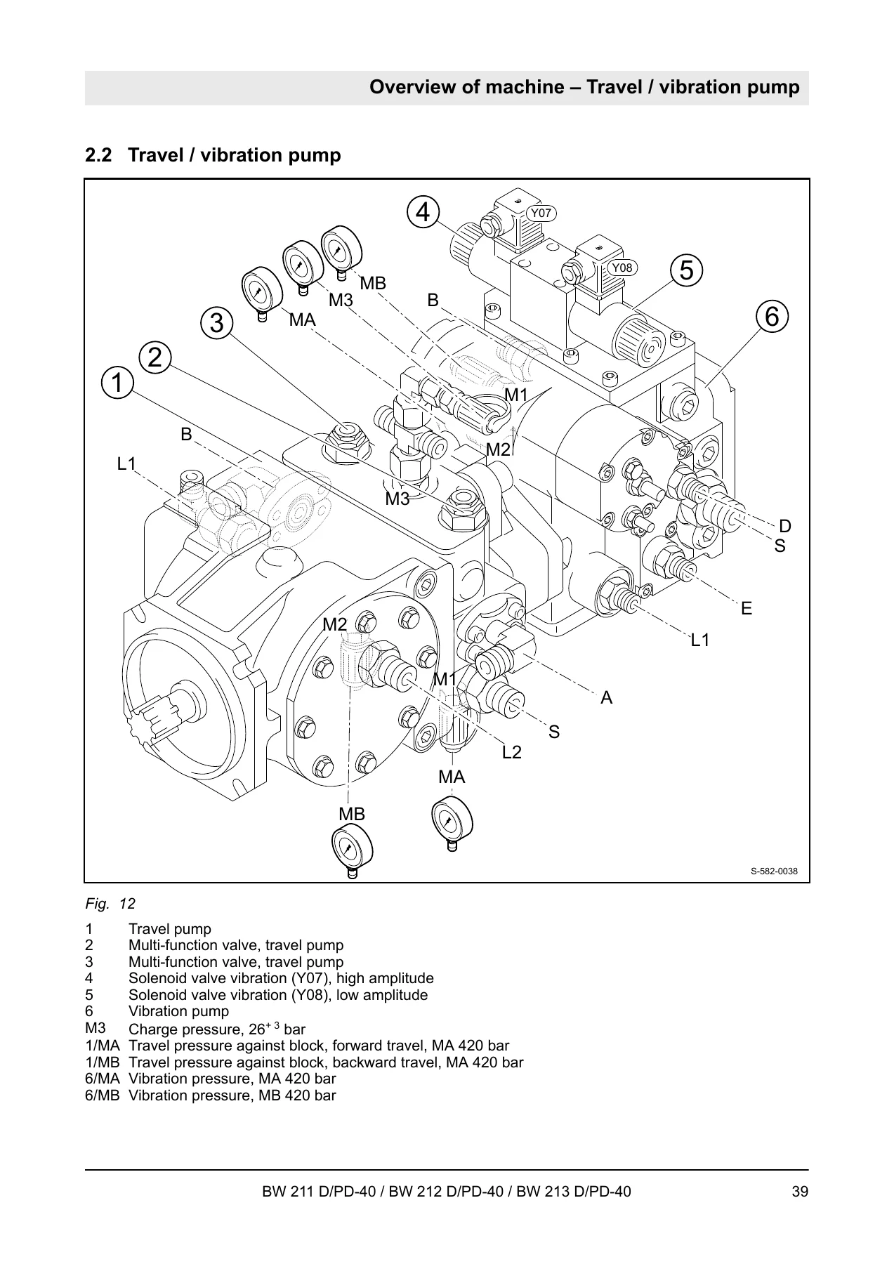
Additional hardware identified in the same chapter includes a Sauer 90R 075 travel pump (75 cm3/rev, 172.9 l/min, high-pressure limitation 400 + 20 bar, charge pressure at high idle 26 + 3 bar), Poclain MSE 18 1 CX drum drive motor (2800 cm3/rev), Sauer 51D 110 axle travel motor (110 / 33 cm3/rev), Sauer 42R 041 vibration pump (41 cm3/rev, starting pressure 420 + 20 bar), A10FM 45 vibration motor, HY/ZFS11/16 steering/charge gear pump (16 cm3/rev, max. steering pressure against end stops 200 + 20 bar), Danfoss OSPC 500 ON steering valve, and Dana CHC 192/51HD rear axle with No-Spin differential, 100% locking and 43.72 reduction. Engine idle data includes low idle 900 ± 200 rpm, high idle 2430 ± 50 rpm, valve clearances 0.3 mm intake and 0.5 mm exhaust, and injection-valve opening pressure 220 bar.
Chapters Covered
- 1 General — purpose of the manual, safety, responsible persons, fuels and lubricants, parking and emergency procedures, maintenance and repair rules
- 1.3 Fuels and lubricants — Deutz DQC engine-oil classes, viscosity, fuel quality and winter fuel, coolant water quality and protection agent, lubricant list
- 2 Overview of machine — diesel engine, travel/vibration pump, drum layout
- 3 Technical data — BW 211 D/PD-40, BW 212 D/PD-40 (58243, 58248, 58356), BW 212 D-40 (58348, 58356), BW 213 D/PD-40, additional component data
- 4 Electric systems — central electrics, fuse assignment, operator’s stand and monitoring board A15, wiring, jump starting, sensors and switches, solenoids Y01 / Y13 / Y120, heating flange R19, MESSX A83, seat-contact module A68, vibration module K04, speedometer module A05, Deutsch and magnetic-coil plugs
- 5 Diesel engine — service and starter sides, lubrication and coolant circuits, thermostat, fuel supply, injection system, injection-pump and injection-valve service, compression check, maintenance tables
- 6 Hydraulic system — open and closed circuits, travel / vibration / drum / axle motors, gear pumps, steering valve, charge / travel / vibration / steering circuits, pressure tests, flushing and bleeding
- 7 Air conditioning — R134a principles, compressor oil, components, emptying, evacuation, filling, steam table, maintenance
- 8 Oscillating articulated joint — overview
- 9 Drum — overview and inspection intervals
- 10 Drive axle — oil levels and changes, wheel nuts, parking-brake adjustment
- 11 Troubleshooting — emergency stop, battery disconnect, towing, electrical measuring method, engine fault tables, starter and generator checks, hydraulic power and axial-piston faults, A/C leak and clutch checks
- 12 Disposal — final shut-down of the machine
- 13 Special tools — electrics, hydraulic tests and flushing, articulated joint, drum
- 14 Index
- Appendix A — circuit diagrams
Taken as a whole, the BOMAG BW 211 BW 212 BW 213 D/PD-40 Service Training Manual 008 401 91 walks a technician from machine identity and fluids through every major energy path on the roller: 12 V control and monitoring, the Deutz 2012 injection and cooling package, closed-circuit travel and vibration hydraulics, cabin air conditioning, the oscillating joint, drum exciters and the Dana drive axle. Interval tables sit next to test ports, leak-oil limits and fault-cause-remedy lists, so the same file can support scheduled service and workshop diagnosis.
Electrical and Electronic Content
Chapter 4 is a working map of the 12 V system rather than a simple fuse list. It locates the monitoring board A15, main and cabin fuses, travel-lever proximity switches B13 and B14, hydraulic-filter differential switch B21, diesel-tank level sensor R03, coolant float switch B55, air-filter vacuum switch B03, water-in-fuel sensor B124, fuel pre-heating R79, oil-pressure switch B06 and coolant-temperature switch B30. Shutdown and speed hardware includes boost-fuel solenoid Y01, engine shutdown actuator Y13 and engine solenoid actuator Y120. Cold-start hardware includes heating flange R19 with a control check. Optional and monitoring modules covered in the same chapter include MESSX A83, acceleration transducer B62, air-conditioning control A108, seat-contact module A68, vibration module K04 and speedometer module A05. Connector practice for Deutsch DT/DTM plugs and magnetic coil plugs is included so harness work matches the drawings in the appendix.
Engine, Hydraulics and Air Conditioning Tasks
The diesel chapter shows service-side and starter-side layouts, then lubrication and coolant flow, thermostat replacement, fuel supply, Bosch plug-in injection pumps of the 2012 series, start-of-injection measurement when a pump is renewed, injection-valve replacement and bench checks, and compression comparison between cylinders. Maintenance is grouped as checks before start-up and work at 500, 1000, 2000 and 3000 operating hours plus as-required air-filter and water-separator service. Valve clearances and opening pressure quoted above are the figures the text expects you to use, not generic Deutz values from memory.
Hydraulics occupy a large middle of the book because travel, vibration and steering are all hydrostatic. After explaining open versus closed circuits and the swash-plate principle, the text covers charge, travel, vibration and steering circuits, then tests: travel-pump neutral, travel-circuit pressures, exciter-shaft speed, vibration-motor leakage and steering pressures. Flushing the travel circuit and the vibration circuit, then bleeding the system, are written as workshop sequences with filter orientation warnings. Air conditioning is treated as its own system: R134a properties, PAG refrigeration oil, compressor and monitoring devices, emptying for repair, drying and evacuation, filling steps and an R134a steam table, with inspection at 250 and 500 hours.
Drum, Axle, Joint and Fault Finding
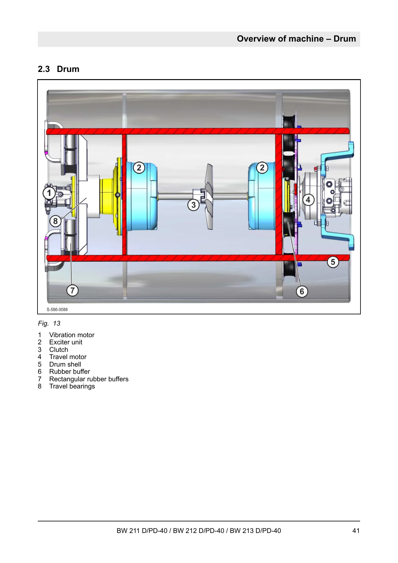
Drum service is scheduled at 250 and 1000 hours and as required. The cutaway in the overview identifies the vibration motor, dual exciter units, clutch, travel motor, drum shell, rubber buffers and travel bearings. Drive-axle work covers tyre checks, oil in the axle and wheel hubs at 250 hours, oil changes and fastener retightening at 1000 hours, and parking-brake adjustment as required. The oscillating articulated joint has its own overview and a special-tool list. Troubleshooting then gathers emergency procedures, electrical measuring method and circuit-diagram reading, engine no-start and misfire tables, starter and generator checks, insufficient hydraulic power, axial-piston pump and motor faults, and refrigerant-circuit diagnosis including leak test and magnetic-clutch check. Special tools are split among electrics, hydraulic test and flush equipment, the articulated joint and the drum.
Use This Manual on the Job
With the BOMAG BW 211 BW 212 BW 213 D/PD-40 Service Training Manual 008 401 91 you can identify the correct D-40 or PD-40 machine and serial group, select fuels and lubricants that match the Deutz DQC and coolant rules in the book, trace 12 V faults through fuses and the A15 board, service the BF4M 2012 C injection and cooling system, set and test travel and vibration hydraulics, flush contaminated circuits, work the R134a cabin system, and follow drum, axle and joint intervals. Correct pressures, displacements, valve clearances and shutdown logic matter on these rollers because travel, vibration and steering share charge oil and the monitoring board can shut the engine down on oil pressure, coolant, filter restriction or water in fuel. Guessing those values from a similar BOMAG model is how pumps are over-pressured and exciters are left off-speed.
After payment you receive an instant PDF download. There is no printed shipment to wait for. Open the file on a workshop PC, tablet or phone and print the pages you need for a specific test, flush or wiring job. Keep 008 401 91 EN with the machine’s operating instructions and spare-parts catalogue so training content, daily operation and part numbers stay aligned.

Reviews
There are no reviews yet.