★ TRUSTED BY 321,897+ PROFESSIONALS WORLDWIDE
🏒
Trusted Business
Verified & Licensed
πŸ›‘οΈ
Virus Free Files
100% Safe Downloads
πŸ”’
Secure Payment
SSL Protected
⚑
Instant Delivery
Available Immediately
Sale!

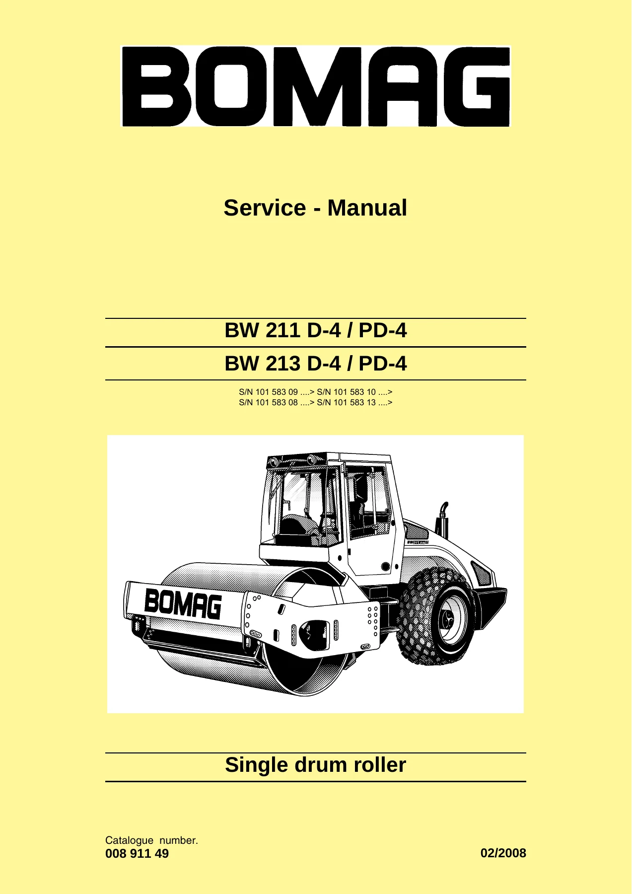
BOMAG BW 211 D-4 PD-4 BW 213 D-4 PD-4 Single Drum Roller Service Manual – Complete Workshop PDF

Original price was: $39.95.Current price is: $24.95.

Complete 1,046-page BOMAG service manual for BW 211 D-4/PD-4 and BW 213 D-4/PD-4 single drum rollers. Covers engine, hydraulics, electrics, drum, axle, air conditioning, wiring diagrams, and full repair procedures.

⚑
Instant PDF Download
Available immediately
πŸ’Ύ
Save to Your Device
Download & keep forever
πŸ›‘οΈ
Antivirus Scanned
100% virus-free
🌍
Trusted Worldwide
175,000+ customers

Description

BOMAG BW 211 D-4 / PD-4 and BW 213 D-4 / PD-4 Service Manual

This BOMAG BW 211 D-4 PD-4 BW 213 D-4 PD-4 Single Drum Roller Service Manual is the complete workshop documentation for the D-4 generation of these machines, published under BOMAG document number 008 911 49. It spans 1,046 pages and is written for trained mechanics carrying out maintenance, repair, diagnosis, and overhaul work on these single drum rollers. Every major system is covered, from the Deutz diesel engine through the hydrostatic travel and vibration circuits, the drum assembly, the oscillating articulated joint, the rear axle, and the complete electrical system including wiring diagrams.

File Details

  • Manual type: Service / Workshop Manual
  • Brand: BOMAG
  • Models covered: BW 211 D-4, BW 211 PD-4, BW 213 D-4, BW 213 PD-4
  • Document number: 008 911 49
  • Language: English (supplier documentation sections include German, French, Italian, and Spanish alongside English)
  • Page count: 1,046
  • File format: PDF

Chapters Covered

  • General – Introduction, safety regulations, general repair instructions, tightening torques
  • Maintenance – Maintenance chart, fuels and lubricants, running-in instructions
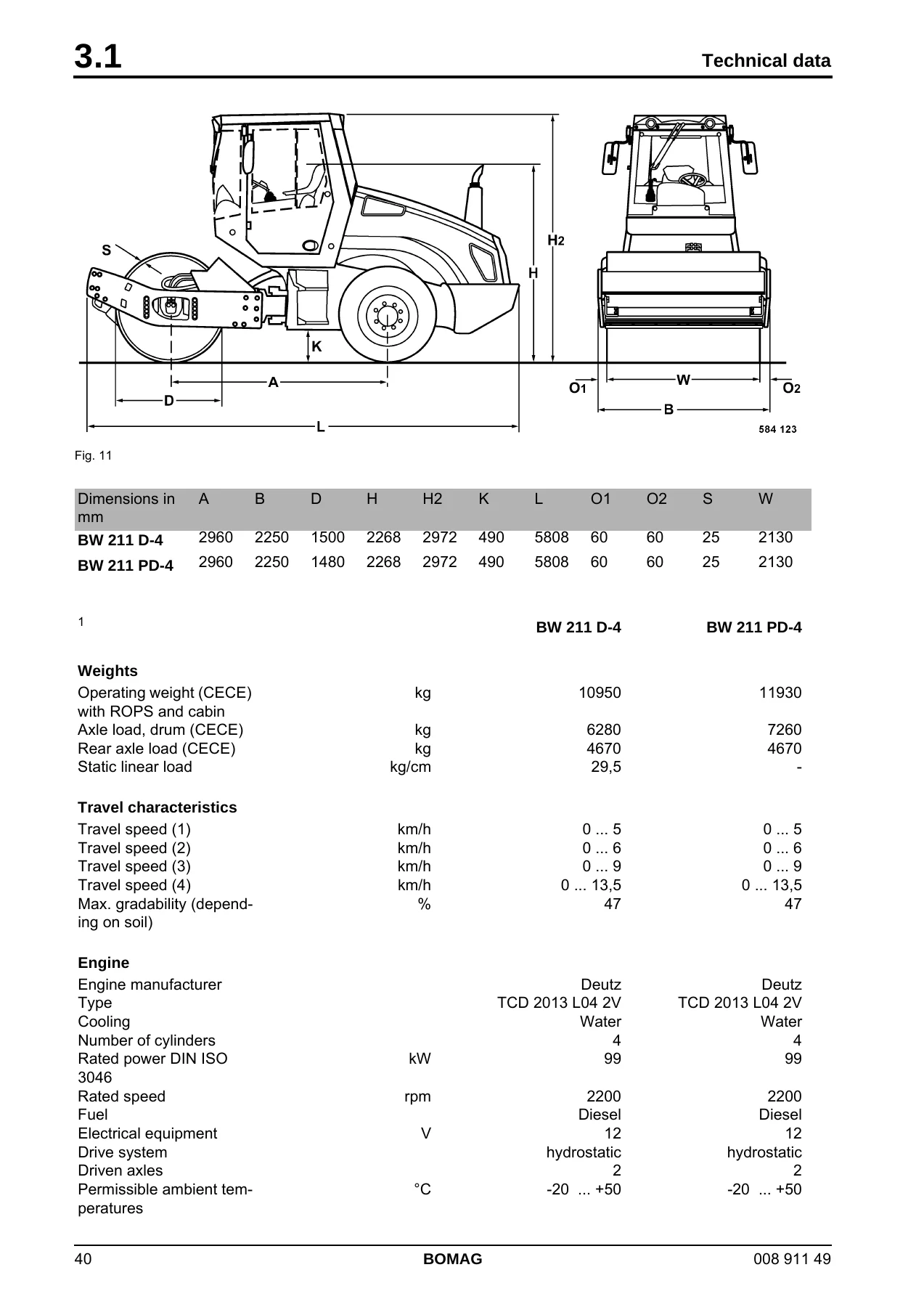
  • Technical data – Dimensions, weights, travel characteristics, engine and hydraulic data
  • Connection overview – Travel pump ports, functions, and connections
  • Tests and adjustments – Rotation speeds, neutral positions, pressure tests, vibrator shaft speeds, leakage rates, steering circuit pressures
  • Flushing and bleeding – Special tools, travel circuit flushing, vibration circuit flushing, bleeding procedures
  • Fundamental electrics – Circuit diagrams, terminal designations, CAN-Bus, resistance, Ohm’s law, batteries, three-phase generator, starter, sensors, plug connectors, electric modules
  • Special tools, electrics – Measuring equipment, crimping tools, Deutsch and AMP contact tools
  • Electronic modules – BEM Evib-meter, electrics module A68, electric module K04, heating/air conditioning control, speedometer module
  • Service Training – Travel system, vibration, steering, with hydraulic schematics and troubleshooting charts
  • Engine – Deutz TCD 2013 L04 2V diesel engine, fuel system, cooling system, lubrication, valve clearance, compression, special tools
  • Air conditioning system – Physical basics, refrigerant R134a, compressor oil, components, service, troubleshooting, steam table
  • Replacing the cab window panes – Assembly, tools, removal and installation
  • Drum – Repair overview, removal and installation, dismantling and assembling exciter unit, change-over weights, rubber buffers
  • Oscillating articulated joint – Repair overview, removal, dismantling, assembly
  • Suppliers documentation – Travel pump (Sauer Series 90), vibration pump (Sauer Series 42), drum drive (Poclain MS/MSE), vibration motor (Brueninghaus A10FM/A10FE), axle drive motor (Sauer Series 51), axle
  • Circuit diagrams – Hydraulic diagram 581 202 03, wiring diagrams 582 702 09, 582 702 29, 582 702 41

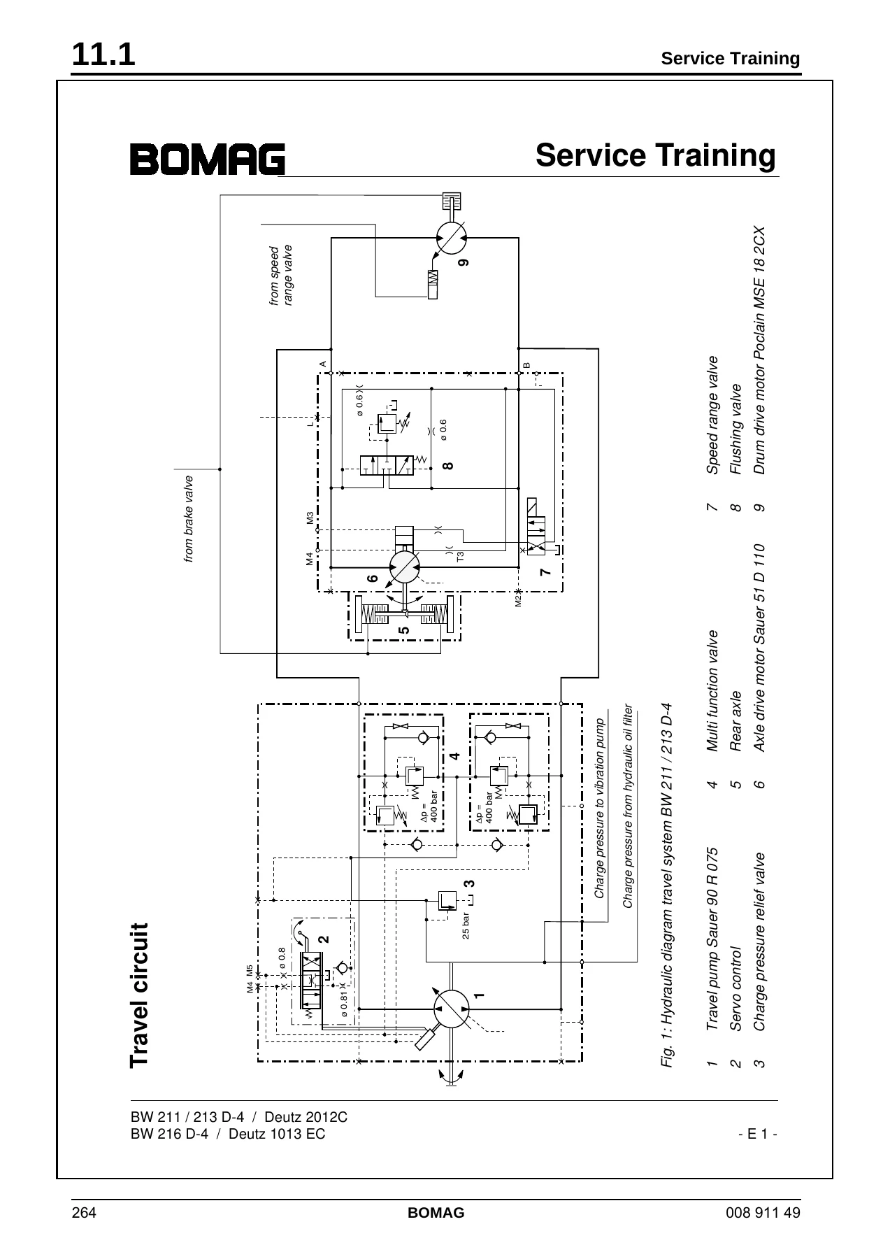
This BOMAG single drum roller service manual gives a technician the full factory repair logic for the BW 211 D-4 and BW 213 D-4 machines. The travel system chapter alone walks through the Sauer 90R075 travel pump, the Poclain MSE 18 2CX drum drive motor, and the Sauer 51D110 axle motor with pressure test points and adjustment values. The vibration section covers the Sauer 42R041 pump and the A10FM 45 motor with flushing valve. The electrical chapters go from basic terminal numbering through CAN-Bus diagnostics, fault codes, and the BEM Evib-meter module. The engine section covers the Deutz TCD 2013 L04 2V in detail, including fuel filter service, coolant temperature switch, valve clearance adjustment, compression testing, and the complete special tool list. Wiring diagrams for the whole machine are included at the back.

Complete PDF Bookmark Tree

Complete Bookmarks

The complete bookmarks in the β€œBOMAG BW 211 D-4 PD-4 BW 213 D-4 PD-4 Single Drum Roller Service Manual – Complete Workshop PDF” are as follows:

BW 211 D-4 / PD-4p. 1
BW 213 D-4 / PD-4p. 1
S/N 101 583 09 ….> S/N 101 583 10 ….>p. 1
S/N 101 583 08 ….> S/N 101 583 13 ….>p. 1
Single drum rollerp. 1
1 Generalp. 7
1.1 Introductionp. 8
Safety regulationsp. 9
Important notesp. 9
Generalp. 9
Precautions and codes of conduct for welding workp. 9
Old oilsp. 10
Hydraulicsp. 10
Fuelsp. 11
Hot fuelsp. 11
Synthetic rubberp. 11
Poisonous substancesp. 11
Enginep. 11
Air conditioning systemp. 12
Batteryp. 12
Poisonous substancesp. 13
Special safety regulationsp. 13
General repair instructionsp. 14
Generalp. 14
Electricsp. 14
Batteryp. 15
Hydraulic systemp. 16
Air conditioning systemp. 17
Notes on cleanliness for Common Rail enginesp. 18
Fig. 1p. 18
Fuel hosesp. 20
Fig. 2p. 20
Gaskets and mating surfacesp. 21
Fig. 3p. 21
Fig. 4p. 21
Feather keys and keywaysp. 22
Fig. 5p. 22
Ball and roller bearingsp. 22
Fig. 6p. 22
Fig. 7p. 23
Screws and nutsp. 23
Fig. 8 Identification of screwsp. 24
Fig. 9 Identification of nutsp. 24
Fig. 10 Identification of nuts in clock systemp. 25
Tightening torquesp. 26
2 Maintenancep. 31
2.1 General notes on maintenancep. 32
Notes on the fuel systemp. 32
Notes on the engine performancep. 32
Notes on the hydraulic systemp. 32
Notes on the cooling systemp. 32
2.2 Table of fuels and lubricantsp. 34
2.3 Running-in instructionsp. 35
2.4 Maintenance chartp. 36
3 Technical datap. 39
Technical datap. 40
Fig. 11p. 40
Fig. 12p. 42
Noise valuep. 46
Vibration valuep. 46
4 Connection overviewp. 47
Connection overview
Fig. 1 Travel pumpp. 48
1 Control solenoid, high frequencyp. 49
2 Control solenoid, low frequencyp. 49
3 Multi-function valve 400 bar (boost check and pressure relief valve), travel systemp. 49
4 Connection, charge pressure to brake solenoid valve, travel speed range selection and charge oil supply for vibration pumpp. 49
5 Multi-function valve 400 bar (boost check and pressure relief valve), travel systemp. 49
6 Setscrew, mechanical neutral positionp. 49
7 Connection L, leak oil connection to vibration pumpp. 49
8 Lever, travel controlp. 49
9 Pilot pressure test portp. 49
10 High pressure port B, high pressure reversep. 49
11 Charge pressure relief valve, 26 barp. 49
12 Adjustment screw, low frequencyp. 49
13 Connection L2, leak oil to tankp. 49
14 Pressure test port MB, high frequencyp. 49
15 High pressure test port MA, low frequencyp. 49
16 High pressure port A, low frequencyp. 49
17 High pressure port B, high frequencyp. 49
18 Charge pump, internalp. 49
19 Connection L2, to drum drive motor (flushing)p. 49
20 Adjustment screw, high frequencyp. 49
21 Connection D, charge pressure to filterp. 49
22 Multi function valve 345 bar (boost check and pressure relief valve), vibration drive high frequencyp. 49
23 Connection S, suction line charge pump from hydraulic oil tankp. 49
24 Multi function valve 345 bar (boost check and pressure relief valve), vibration drive low frequencyp. 49
25 Charge pressure relief valve, vibration pump (blocked)p. 49
26 Connection E, charge oil from travel pumpp. 49
27 Connection L1, leak oil connection to travel pumpp. 49
28 Pressure test port MB, high pressure reversep. 49
29 Charge oil from filterp. 49
30 Pressure test port MA, high pressure forwardp. 49
31 High pressure port A, high pressure forwardp. 49
32 Setscrew, mechanical neutral position, vibrationp. 49
33 Leak oil connection D, leak oil from axle drive motorp. 49
34 Leak oil connection A, leak oil from travel pumpp. 49
35 Leak oil connection G, leak oil from drum drive motorp. 49
36 Leak oil connection F, leak oil from vibration motorp. 49
37 Radiator inletp. 49
5 Tests and adjustmentsp. 51
5.1 Special tools, tests and adjustmentsp. 52
Fig. 1p. 52
Fig. 2p. 52
Fig. 3p. 52
Fig. 4p. 52
Fig. 5p. 53
Fig. 6p. 53
Fig. 7p. 53
Fig. 8p. 53
Fig. 9p. 54
Fig. 10p. 54
Fig. 11p. 54
Fig. 12p. 54
Fig. 13p. 55
Fig. 14p. 55
5.2 Checking the rotation speedsp. 56
Fig. 1p. 56
Check the engine speedp. 56
Fig. 2p. 56
Checking the exciter shaft speedp. 57
Fig. 3p. 57
5.3 Checking / adjusting the neutral positions of the travel pumpp. 58
Fig. 1p. 58
Fig. 2p. 58
Fig. 3p. 58
Fig. 4p. 59
Fig. 5p. 59
Fig. 6p. 59
Fig. 7p. 59
5.4 Pressure tests in the travel circuitp. 60
Fig. 1p. 60
Fig. 2p. 60
Fig. 3p. 60
Fig. 4p. 61
5.5 Checking / adjusting the vibrator shaft speedsp. 62
Fig. 1p. 62
Fig. 2p. 62
Fig. 3p. 62
5.6 Pressure measurements in the vibration circuitp. 63
Fig. 1p. 63
Fig. 2p. 63
5.7 Check the leakage rate of the vibration motorp. 64
Fig. 1p. 64
Fig. 2p. 64
Fig. 3p. 64
5.8 Pressure test in steering circuitp. 65
Fig. 1p. 65
Fig. 2p. 65
Fig. 3p. 65
Fig. 4p. 66
Fig. 5p. 66
6 Flushing and bleedingp. 67
6.1 Special tools for flushingp. 68
Fig. 1p. 68
1. Filling and filtering unit with oil bagp. 68
2. Filter elementp. 68
Fig. 2p. 68
3. Flushing filter (S connection)p. 68
4. Filter element 1mp. 68
5. Flushing hose 20S – 25S (2 pieces)p. 68
6. Screw socket R1β€œ – 25S (2 pieces)p. 68
Fig. 3p. 68
7. Flushing filter (L connection)p. 68
8. Filter elementp. 68
9. Flushing hose 15L (2 pieces)p. 68
10. Screw socket R3/4β€œ — 15L (2 pieces)p. 68
Fig. 4p. 68
11. SAE-flange 1β€œ – 20Sp. 68
12. O-ringp. 68
Fig. 5p. 69
13. Flanged plate 1β€œ – 25Sp. 69
14. O-ringp. 69
Fig. 6p. 69
15. Reducing fitting 18L – 15Lp. 69
Fig. 7p. 69
16. Reducing fitting 25S – 20Sp. 69
Fig. 8p. 69
17. Reducing fitting 20S – 16Sp. 69
Fig. 9p. 70
18. Connecting socket 15Lp. 70
Fig. 10p. 70
19. Connecting socket 18Lp. 70
Fig. 11p. 70
20. Connecting socket 16Sp. 70
Fig. 12p. 70
21. Connecting fitting 20Sp. 70
Fig. 13p. 71
22. Connecting fitting 25Sp. 71
Fig. 14p. 71
23. Angular fitting 18Lp. 71
Fig. 15p. 71
24. Elbow fitting 16Lp. 71
Fig. 16p. 71
25. Elbow 20Sp. 71
Fig. 17p. 72
26. Elbow 25Sp. 72
Fig. 18p. 72
27. Pipe connection 16S – 16Sp. 72
Fig. 19p. 72
28. Connecting hose 15Lp. 72
6.2 Flushing – generalp. 73
Changing a componentp. 73
Chips (abrasion) in the oilp. 73
Open and clean all components in the oil circuit, replace if necessary.p. 73
Clean all high pressure hoses in the oil circuit, replace if necessary.p. 73
If abrasion is found in the travel circuit you should also flush the vibration circuit.p. 73
If abrasion is found in the vibration circuit you should also flush the travel circuit.p. 73
Before flushingp. 73
Fig. 1p. 73
Change the hydraulic oil filter element (1).p. 73
Fig. 2p. 73
Filter the tank content with the filling and filtering unit and pump it into the oil bag.p. 73
Mark all hoses and disconnect them from the hydraulic oil tank.p. 73
Clean the oil tank thoroughly from inside, if necessary remove the complete tank cover.p. 73
Reconnect all hoses.p. 73
Fill the hydraulic oil tank again with the filling and filtering unit.p. 73
Bleedingp. 73
Fig. 3p. 73
Always bleed closed hydraulic circuits if lines had been removed or connected.p. 73
Servicing the flushing filter kitp. 74
Fig. 4p. 74
Replace the filter element of the flushing filter when the red control pin of the contamination indicator is pressed out during the filtering process.p. 74
Clean hoses and connections and store the flushing kit in a clean and protected environment.p. 74
Flushing schematic travel circuit (distribution travel pump)
1 Elbow union (tool)p. 76
2 Connecting union (tool)p. 76
3 Drum drive motorp. 76
4 Axle motorp. 76
5 Screw socket R1 – 25S (tool)p. 76
6 Flushing hose 25S – 20S (tool)p. 76
7 Flushing hose 25S – 20S (tool)p. 76
8 Flushing filter with filter element 1m (tool)p. 76
9 Elbow union (tool)p. 76
10 Reducing fitting (tool)p. 76
11 Travel pumpp. 76
12 High pressure hose (B, drum drive motor reverse)p. 76
13 High pressure hose (A, drum drive motor forward)p. 76
14 High pressure hose (B, axle motor reverse)p. 76
15 High pressure hose (A, axle motor forward)p. 76
16 High pressure hose (B, axle motor reverse)p. 76
17 High pressure port (B, drum drive motor reverse)p. 76
18 Flushing hose 25S – 20S (tool)p. 76
19 Flushing hose 25S – 20S (tool)p. 76
6.4 Flushing the travel circuit (travel pump distribution)p. 77
Flushing the drum drivep. 77
Fig. 1p. 77
1. Disconnect the high pressure hose 12 (see chapter "Flushing schematic – travel circuit") from the travel pump (high pressure port 17) and connect it with the flushing hose (7) (flushing filter inlet "IN").p. 77
2. Connect the flushing hose (6) (flushing filter outlet "OUT") to the (high pressure port 17) on the travel pump.p. 77
Fig. 2p. 77
3. Take the drum drive motor out of the hydraulic circuit by joining the high pressure hoses (12 and 13) on the drum drive motor together.p. 77
Fig. 3p. 78
Fig. 4p. 78
4. Block drums and wheels with suitable chocks.p. 78
Fig. 5p. 78
Fig. 6p. 78
5. Start the engine and shift the travel lever to travel direction forward.p. 78
6. Perform the flushing process at various engine speeds for approx. 10 minutes.p. 78
7. Shut down the engine.p. 78
8. Reconnect the hydraulic hoses (12 and 13) to the drum drive motor.p. 78
Fig. 7p. 79
9. Jack up the front of the machine, so that the drum can rotate freely.p. 79
10. Secure the rear wheels with chocks.p. 79
11. Pre-select the slow speed range.p. 79
Fig. 8p. 79
Fig. 9p. 79
12. Start the engine, run it with maximum speed and shift the travel lever to travel direction forward.p. 79
13. Run the flushing procedure for approx. 10 minutes. During this process keep changing the pump flow by shifting the travel lever several times between full and halve forward travel.p. 79
14. Shut down the engine.p. 79
15. Remove the flushing filter and reconnect the high pressure lines.p. 79
Flushing the axle drivep. 80
Fig. 10p. 80
16. Disconnect the high pressure hose 14 (see chapter "Flushing schematic – travel circuit") from the travel pump (high pressure port 16) and connect it with the flushing hose (18) (flushing filter inlet "IN").p. 80
17. Connect the flushing hose (19) (flushing filter outlet "OUT") to the (high pressure port 16) on the travel pump.p. 80
Fig. 11p. 80
18. Take the axle drive motor out of the hydraulic circuit by joining the high pressure hoses (14 and 15) on the axle drive motor together.p. 80
Fig. 12p. 80
Fig. 13p. 81
19. Block drums and wheels with suitable chocks.p. 81
Fig. 14p. 81
Fig. 15p. 81
20. Start the engine and shift the travel lever to travel direction forward.p. 81
21. Perform the flushing process at various engine speeds for approx. 10 minutes.p. 81
22. Shut down the engine.p. 81
23. Reconnect the hydraulic hoses (14 and 15) to the axle drive motor.p. 81
Fig. 16p. 81
24. Jack up the rear of the machine, so that the wheels can rotate freely.p. 81
25. Secure the drum with wheel chocks.p. 81
26. Pre-select the slow speed range.p. 81
Fig. 17p. 82
Fig. 18p. 82
27. Start the engine, run it with maximum speed and shift the travel lever to travel direction forward.p. 82
28. Run the flushing procedure for approx. 10 minutes. During this process keep changing the pump flow by shifting the travel lever several times between full and halve forward travel.p. 82
29. Shut down the engine.p. 82
30. Remove the flushing filter and reconnect the high pressure lines.p. 82
31. Bleed the travel circuit (see corresponding chapter).p. 82
32. After completing the bleeding process circulate the tank content with the filtering unit for another 15 minutes.p. 82
Fig. 19p. 82
33. Check the hydraulic oil level in the tank, fill up if necessary.p. 82
34. Check all connections for leaks with the engine running (visual inspection).p. 82
35. Perform a test drive, load the travel system in forward and reverse, e.g. by driving uphill or starting on a gradient.p. 82
36. Check all ports and connections for leak tightness (visual inspection).p. 82
Flushing schematic travel circuit (distribution axle motor)
1 Elbow union (tool)p. 87
2 Connecting union (tool)p. 87
3 Drum drive motorp. 87
4 Axle motorp. 87
5 Screw socket R1 – 25S (tool)p. 87
6 not usedp. 87
7 not usedp. 87
8 Flushing filter with filter element 1m (tool)p. 87
9 not usedp. 87
10 Reducing fitting (tool)p. 87
11 Travel pumpp. 87
12 High pressure hose (drum drive motor reverse)p. 87
13 High pressure hose (drum drive motor forward)p. 87
14 High pressure hose (B, axle motor reverse)p. 87
15 High pressure hose (A, axle motor forward)p. 87
16 High pressure hose (B, axle motor reverse)p. 87
17 not usedp. 87
18 Flushing hose 25S – 20S (tool)p. 87
19 Flushing hose 25S – 20S (tool)p. 87
6.6 Flushing the travel circuit (axle motor distribution)p. 88
Flushing the drum drivep. 88
Fig. 1p. 88
1. Disconnect the high pressure hose 14 (see chapter "Flushing schematic – travel circuit") from the travel pump (high pressure port 16) and connect it with the flushing hose (19) (flushing filter inlet "IN").p. 88
2. Connect the flushing hose (18) (flushing filter outlet "OUT") to the (high pressure port 16) on the travel pump.p. 88
Fig. 2p. 88
3. Take the drum drive motor out of the hydraulic circuit by joining the high pressure hoses (12 and 13) on the drum drive motor together.p. 88
Fig. 3p. 89
Fig. 4p. 89
Fig. 5p. 89
4. Block drums and wheels with suitable chocks.p. 89
Fig. 6p. 89
5. Start the engine and shift the travel lever to travel direction forward.p. 89
6. Perform the flushing process at various engine speeds for approx. 10 minutes.p. 89
7. Shut down the engine.p. 89
8. Reconnect the hydraulic hoses (12 and 13) to the drum drive motor.p. 89
Fig. 7p. 90
9. Jack up the front of the machine, so that the drum can rotate freely.p. 90
10. Secure the rear wheels with chocks.p. 90
11. Pre-select the slow speed range.p. 90
Fig. 8p. 90
Fig. 9p. 90
12. Start the engine, run it with maximum speed and shift the travel lever to travel direction forward.p. 90
13. Run the flushing procedure for approx. 10 minutes. During this process keep changing the pump flow by shifting the travel lever several times between full and halve forward travel.p. 90
14. Shut down the engine.p. 90
Flushing the axle motorp. 91
Fig. 10p. 91
15. Jack up the rear of the machine, so that the wheels can rotate freely.p. 91
16. Secure the drum with wheel chocks.p. 91
17. Pre-select the slow speed range.p. 91
Fig. 11p. 91
Fig. 12p. 91
18. Start the engine, run it with maximum speed and shift the travel lever to travel direction forward.p. 91
19. Run the flushing procedure for approx. 10 minutes. During this process keep changing the pump flow by shifting the travel lever several times between full and halve forward travel.p. 91
20. Shut down the engine.p. 91
21. Remove the flushing filter and reconnect the high pressure lines.p. 91
22. Bleed the travel circuit (see corresponding chapter).p. 91
23. After completing the bleeding process circulate the tank content with the filtering unit for another 15 minutes.p. 91
Fig. 13p. 92
24. Check the hydraulic oil level in the tank, fill up if necessary.p. 92
25. Check all connections for leaks with the engine running (visual inspection).p. 92
26. Perform a test drive, load the travel system in forward and reverse, e.g. by driving uphill or starting on a gradient.p. 92
27. Check all ports and connections for leak tightness (visual inspection).p. 92
Flushing schematic for vibration drive
1 Elbow union (tool)p. 93
2 Connecting union (tool)p. 93
3 Vibration motorp. 93
4 Vibration pumpp. 93
5 Screw socket R1 – 25S (tool)p. 93
6 Flushing hose 25S – 20S (tool)p. 93
7 Flushing hose 25S – 20S (tool)p. 93
8 Flushing filter with filter element 1m (tool)p. 93
9 SAE flange (tool)p. 93
10 High pressure hose (B, high frequency)p. 93
11 High pressure hose (A, low frequency)p. 93
6.8 Flushing the vibration circuitp. 94
Fig. 1p. 94
1. Disconnect the high pressure hose 10 (see chapter "Flushing schematic – vibration circuit") from the vibration pump (4) and connect it with the flushing hose (7) (flushing filter inlet "IN").p. 94
2. Connect the flushing hose (6) (flushing filter outlet "OUT") to the (high pressure port A) on the vibration pump.p. 94
Fig. 2p. 94
3. Take the vibration motor out of the hydraulic circuit by joining the high pressure hoses (10 and 11) on the vibration motor together.p. 94
Fig. 3p. 95
Fig. 4p. 95
4. Block drums and wheels with suitable chocks.p. 95
Fig. 5p. 95
Fig. 6p. 95
5. Switch on vibration with high frequency.p. 95
6. Start the engine and run it with maximum speed.p. 95
7. Flush the circuit for approx. 10 minutes, thereby switch the vibration on and off at intervals of approx. 30 seconds.p. 95
8. Shut down the engine.p. 95
9. Reconnect the hydraulic hoses (10 and 11) to the vibration motor.p. 95
Fig. 7p. 96
10. Unscrew the fastening screws for the vibration motor and pull the motor out of the coupling.p. 96
Fig. 8p. 96
Fig. 9p. 96
11. Start the engine and run it with maximum speed.p. 96
12. Run the flushing procedure for approx. 10 minutes. Switch the vibration on and off at intervals of approx. 30 seconds.p. 96
13. Shut down the engine.p. 96
14. Remove the flushing filter and reinstall the vibration motor.p. 96
15. Bleed the vibration circuit (see corresponding chapter).p. 96
16. After completing the bleeding process circulate the tank content with the filtering unit for another 15 minutes.p. 96
Fig. 10p. 97
17. Check the hydraulic oil level in the tank, fill up if necessary.p. 97
18. Test drive.p. 97
19. Check all ports and connections for leak tightness (visual inspection).p. 97
6.9 Bleeding the travel circuitp. 98
1. Install a pressure test hose to the charge pressure test port.p. 98
2. Install a pressure test hose each to the high pressure test ports.p. 98
Fig. 1p. 98
3. Actuate the emergency stop switch.p. 98
Fig. 2p. 98
4. Hold the open ends of the pressure test hoses (Fig. 2) into a container.p. 98
5. Operate the starter motor for approx. 30 seconds. Wait one minute and repeat this procedure, until oil starts to run out from the pressure test hoses.p. 98
6. Remove the pressure test hoses.p. 98
Fig. 3p. 98
7. Unlock the emergency stop switchp. 98
Fig. 4p. 99
8. Connect a 60 bar pressure gauge to the charge pressure test port (Fig. 4) and run the engine max. 15 seconds at idle speed.p. 99
9. Pause for approx. 30 seconds and keep repeating this procedure, until the gauge shows a constant charge pressure reading.p. 99
Fig. 5p. 99
10. Start the engine.p. 99
11. Shift the travel lever (Fig. 5) approx. 1/3 to forward direction.p. 99
12. After approx. 1 to 2 minutes shut down the engine for a minute.p. 99
13. After a waiting time of approx. 1 minute keep repeating this procedure, until the indicated charge pressure drops directly to zero when shutting down the engine.p. 99
6.10 Bleeding the vibration circuitp. 100
1. Install a pressure test hose to the charge pressure test port.p. 100
2. Install a pressure test hose each to the high pressure test ports.p. 100
Fig. 1p. 100
3. Actuate the emergency stop switch.p. 100
Fig. 2p. 100
4. Hold the open ends of the pressure test hoses (Fig. 2) into a container.p. 100
5. Crank the engine approx. 10 seconds with the starter motor. Wait one minute and keep repeating this procedure, until oil starts to run out from the pressure test hoses.p. 100
6. Remove the pressure test hoses.p. 100
Fig. 3p. 100
7. Unlock the emergency stop switchp. 100
Fig. 4p. 101
8. Connect a 60 bar pressure gauge to the charge pressure test port (Fig. 4) and run the engine max. 15 seconds at idle speed.p. 101
9. Wait for approx. 30 seconds and repeat the procedure, until the pressure gauge shows a constant charge pressure.p. 101
Fig. 5p. 101
10. For bleeding switch on vibration with high frequency (Fig. 5).p. 101
11. Start the engine.p. 101
12. After running the engine 1 to 2 minutes pause for approx. one minute.p. 101
13. After a waiting time of approx. 1 minute keep repeating this procedure, until the indicated charge pressure drops directly to zero when shutting down the engine.p. 101
7 Fundamental electricsp. 103
7.1 Understanding circuit diagramsp. 104
Structurep. 104
Table of contentsp. 104
Fig. 6 Table of contentsp. 104
Fig. 7 Function groupsp. 105
Potential cross referencesp. 105
Relay cross referencep. 105
Current pathsp. 106
Fig. 1 Current pathsp. 106
Fig. 1 List of componentsp. 107
Component cross referencesp. 107
Fig. 2 Graphic symbolp. 108
Fig. 3 Graphic symbolp. 108
7.2 Terminal designationsp. 109
7.3 Current and voltagep. 113
Generalp. 113
Voltagep. 113
Fig. 1p. 113
Fig. 2p. 113
Currentp. 114
Fig. 3 Circuitp. 114
Types of currentp. 114
Fig. 1 Direct current (D.C.)p. 114
Fig. 2 Alternating current (A.C.)p. 114
Fig. 3 Pulsating direct currentp. 114
Fig. 4 PWMp. 115
7.4 CAN-Busp. 116
Controller Area Networkp. 116
Fig. 1 CANp. 116
Why CAN?p. 116
Characteristics of CANp. 116
Measuring signalsp. 116
7.5 Resistancep. 118
Resistance and voltage dropp. 118
Fig. 1 Various size resistorsp. 118
Fig. 2 Potentiometer, infinitely adjustable resistorp. 118
Unnecessary resistancesp. 118
Fig. 1 Screw-type terminalsp. 118
Fig. 2 Spring clampsp. 118
Fig. 3p. 119
Fig. 4 Balistol oilp. 119
Fig. 5p. 119
7.6 Series / parallel connectionp. 120
Fig. 1 Series connectionp. 120
Fig. 2p. 120
Fig. 3 Parallel connectionp. 121
Fig. 4p. 121
7.7 Ohm's lawp. 122
Fig. 1p. 122
7.8 Electrical energyp. 122
Fig. 1p. 122
7.9 Formula diagramp. 123
Fig. 1 Formula diagramp. 123
7.10 Metrologyp. 124
Test lampsp. 124
Fig. 1 Test lampp. 124
Fig. 2 Diode test lampp. 124
Multimeterp. 124
Fig. 1 Multimeterp. 124
Fig. 2 Voltage measurementp. 125
Fig. 3 Current measurementp. 125
Clip-on measuring instrumentp. 125
Fig. 1 Clip-on measuring instrumentp. 125
Magnet testerp. 126
Fig. 1 Magnet testerp. 126
Power measurementp. 126
Fig. 2p. 126
7.11 Diodes, relays, fusesp. 127
Diodesp. 127
Fig. 1p. 127
Fig. 2 Marking of the cathodep. 127
Fig. 3 Diode circuitryp. 127
Fig. 4 LEDp. 128
Relaysp. 128
Fig. 1 Relaysp. 128
Fig. 2 Relay circuitryp. 128
Fusesp. 129
Fig. 1p. 129
7.12 Batteriesp. 130
Fig. 1p. 130
Fig. 2p. 130
Fig. 3 Reading the acid levelp. 131
Fig. 4 Battery and generator testerp. 131
Fig. 5 Charge conditionp. 132
7.13 Three-phase generatorp. 133
Generalp. 133
Fig. 6 Rotor with claw polesp. 133
Fig. 7 Stator with 3 windingsp. 133
Fig. 8 3-phase currentp. 134
Fig. 9 Regulator with diode plate and rectifier diodesp. 135
Checking the generatorp. 135
Fig. 10 Connections on the three-phase alternator (exemplary design)p. 136
Fig. 11 Rotorp. 137
Fig. 12 Statorp. 137
Fig. 13p. 138
Fig. 14p. 138
Fig. 15p. 139
Fig. 16p. 139
Fig. 17p. 139
Fig. 18p. 139
7.14 Electric starterp. 141
Fig. 1 Electric starterp. 141
Fig. 2 Switching position during engagementp. 142
Fig. 3 Switching position during startingp. 142
7.15 Telemecanique switchp. 144
Fig. 1 Terminal designationsp. 144
Fig. 2 Disassemblyp. 145
Fig. 3 Folding down the switch blockp. 145
Fig. 4 Pulling out the front elementp. 145
Fig. 5 Assemblyp. 146
Fig. 6 Observe the marks.p. 146
Fig. 7 Assemble the switch blockp. 146
7.16 Inductive proximity switchesp. 147
Fig. 8p. 147
Fig. 9 PNP circuitryp. 147
Fig. 10 NPN circuitryp. 147
Fig. 11p. 147
Fig. 12 Circuit diagram, making contactp. 148
7.17 Angle sensorsp. 148
Sensor with current outputp. 148
Fig. 1 Sensorp. 148
Fig. 2 Connection diagramp. 149
Sensor with voltage outputp. 149
7.18 Plug connectorsp. 150
7.19 Deutsch plug, series DT and DTMp. 150
Generalp. 150
Fig. 3 Crimp connectionsp. 150
DT Seriesp. 151
Fig. 1 DT plug connectionp. 151
Fig. 2 DT Seriesp. 151
Fig. 3 Sectional drawingp. 151
Fig. 4p. 152
Fig. 5p. 153
Fig. 1 DTM plug connectionp. 154
Fig. 2 DTM Seriesp. 154
Fig. 3 Sectional drawingp. 154
Fig. 4p. 155
Fig. 5p. 156
7.20 Plugs and terminals in spring clamping technologyp. 157
Generalp. 157
Fig. 1p. 157
Fig. 2 That's how it worksp. 157
Fig. 3 Connecting clampp. 157
Fig. 4 That's how it worksp. 158
Fig. 5 Test adapterp. 158
Fig. 6 That's how it worksp. 159
Fig. 7 X-COM plug with measuring cablep. 159
Fig. 8 X-COM plug plugged onto the series clampp. 159
7.21 Electric modulesp. 160
Fig. 1p. 160
8 Special tools, electricsp. 161
8.1 Special tools, electricsp. 162
Fig. 2p. 162
Fig. 3p. 162
Fig. 4p. 162
Fig. 5p. 162
Fig. 6p. 163
Fig. 7p. 163
Fig. 8p. 163
Fig. 9p. 164
Fig. 10p. 164
Fig. 11p. 164
Fig. 12p. 164
Fig. 13p. 165
Fig. 14p. 165
Fig. 15p. 165
Fig. 16p. 165
Fig. 17p. 166
Fig. 18p. 166
Fig. 19p. 166
Fig. 20p. 166
Fig. 21p. 167
Fig. 22p. 167
Fig. 23p. 167
Fig. 24p. 167
Fig. 25p. 168
Fig. 26p. 168
Fig. 27p. 168
Fig. 28p. 168
Fig. 29p. 169
Fig. 30p. 169
Fig. 31p. 169
Fig. 32p. 169
Fig. 33p. 170
Fig. 34p. 170
Fig. 35p. 170
Fig. 36p. 170
9 Electronic modulesp. 171
9.1 BEM, BOMAG Evib-meterp. 173
Bild 37p. 174
9.2 Electrics module A68p. 234
9.3 Electric module K04p. 242
9.4 Heating/air conditioning controlp. 246
10 Speedometer Modulep. 253
10.1 Speedometer modulep. 254
Fig. 1 Speedometer modulep. 254
11 Service Trainingp. 257
11.1 Service Trainingp. 259
12 Enginep. 321
12.1 Diesel enginep. 322
Descriptionp. 322
Fig. 1 Engine compartmentp. 322
Fig. 2 Numbering of cylindersp. 322
Fig. 3 Operation sidep. 323
Fig. 4 Exhaust sidep. 324
Fig. 5 Lubrication oil circuitp. 325
Fig. 6 Fuel supplyp. 327
Fig. 7 Coolant diagramp. 328
12.2 Fuel filter and check valvep. 330
Fuel pre-filterp. 330
Fig. 8 Fuel pre-filterp. 330
Main fuel filterp. 331
Fig. 9 Main fuel filterp. 331
Check valvep. 332
Fig. 10 Flow directionp. 332
Fig. 11 Check valvep. 332
Work in the low pressure systemp. 332
12.3 Check, clean the water separatorp. 333
Fig. 12p. 333
12.4 Change the fuel pre-filter cartridgep. 333
Fig. 13p. 333
Fig. 14p. 333
Fig. 15p. 334
Fig. 16p. 334
12.5 Change the fuel filter cartridgep. 334
Fig. 17p. 334
Fig. 18p. 334
12.6 Oil pressure switch and low oil pressure circuitryp. 335
Fig. 1p. 335
12.7 Changing engine oil and oil filter cartridgesp. 336
Fig. 2p. 336
Fig. 3p. 336
Fig. 4p. 336
Fig. 5p. 337
12.8 Coolant temperature switchp. 338
Fig. 1 Coolant temperature switchp. 338
12.9 Disassembling and assembling the coolant temperature switchp. 339
Fig. 2 Temperature switchp. 339
Fig. 3 Coolant temperature switchp. 339
12.10 Removing and installing the thermostatp. 340
Fig. 4p. 340
Fig. 5p. 340
Fig. 6p. 340
Fig. 7p. 340
Fig. 8p. 341
12.11 Checking the thermostat in disassembled statep. 341
Fig. 1p. 341
Fig. 2p. 341
Fig. 3p. 342
12.12 Change the coolantp. 342
Fig. 4p. 342
Fig. 5p. 342
Fig. 6p. 343
12.13 Checking the anti-freeze concentrationp. 343
12.14 Three-phase generatorp. 344
Fig. 1 Generatorp. 344
12.15 Checking / replacing the ribbed V-beltp. 345
Checking the wear limit of the ribbed V- beltp. 345
Fig. 2p. 345
Changing the ribbed V-beltp. 345
Fig. 3p. 345
Fig. 4p. 346
12.16 Boost fuel solenoid valvep. 347
Fig. 5p. 347
12.17 Engine shut-down solenoidp. 348
Fig. 6p. 348
12.18 Air filter, differential pressure switchp. 349
Fig. 7p. 349
12.19 Combustion air filter servicep. 350
Fig. 8 Old designp. 350
Fig. 9 New versionp. 350
Fig. 10p. 350
Removing the main filter elementp. 350
Fig. 11p. 350
Fig. 12p. 351
Cleaning the main filter elementp. 351
Fig. 13p. 351
Fig. 14p. 351
Cleaning the dust bowlp. 351
Fig. 15p. 351
Installing the main filter elementp. 351
Changing the safety filter elementp. 352
Fig. 16p. 352
12.20 Heating flange on enginep. 352
Fig. 1 Heating flangep. 352
Fig. 2p. 353
Fig. 3 Coolant temperature sensorp. 353
Fig. 4 Heating flange function diagramp. 354
12.21 Checking the heating flange controlp. 355
Fig. 1 Monitoring module, old design (A15)p. 355
Fig. 2 Monitoring module, new design (A15)p. 355
12.22 Electric throttle controlp. 356
Fig. 1 Engine solenoidp. 356
Fig. 2 Electric circuit of solenoidp. 356
Fig. 3p. 357
Fig. 4p. 357
12.23 Crankcase – disassembling and assembling the ventilation valvep. 357
Fig. 1p. 357
Fig. 2p. 357
Fig. 3p. 358
Fig. 4p. 358
Fig. 5p. 358
12.24 Disassembling and assembling the starterp. 359
Fig. 1p. 359
Fig. 2p. 359
Fig. 3p. 359
Fig. 4p. 359
12.25 Engine monitoringp. 360
Fig. 1 Monitoring module, old designp. 360
Fig. 2 Monitoring module, new designp. 361
Fig. 3 Differential pressure switchp. 362
Fig. 4 Sensor water separatorp. 362
Fig. 5 Oil pressure switchp. 362
Fig. 6 Coolant temperature switchp. 363
Fig. 7 Coolant temperature switchp. 363
Fig. 8 Emergency stop switchp. 363
12.26 Adjusting the valve clearancep. 364
Adjusting the valve clearancep. 364
Fig. 9p. 364
Fig. 10p. 364
Fig. 11p. 364
Intake valve clearance adjustment in case of exhaust gas recirculationp. 365
Fig. 12p. 365
Fig. 13p. 365
Fig. 14p. 365
Valve adjustment schematicp. 365
12.27 Adjusting the control piston playp. 366
Adjusting the control piston playp. 366
Fig. 15p. 366
Fig. 16p. 366
Adjustment schematicp. 366
12.28 Checking the compressionp. 367
Fig. 1p. 367
Fig. 2p. 367
Fig. 3p. 367
Fig. 4p. 367
Fig. 5p. 368
Fig. 6p. 368
Fig. 7p. 368
Fig. 8p. 368
12.29 Enginep. 369
12.30 Special tools, Deutz engine (TCD 2013 2V)p. 371
13 Air conditioning systemp. 391
13.1 Physical basicsp. 392
Fig. 1p. 392
Fig. 2p. 392
Pressure and boiling pointp. 393
Fig. 3 Steam pressure curvep. 393
Fig. 4 Pressure – Temperature Diagramp. 393
13.2 Refrigerant R134ap. 395
Environmental aspectsp. 396
13.3 Compressor oil / refrigeration oilp. 396
13.4 Working principle of the air conditioning systemp. 397
Fig. 1 Principle sketch of an air conditioning systemp. 397
13.5 Monitoring devicesp. 397
Fig. 2 Monitoring chain consisting of:p. 398
13.6 Description of componentsp. 398
Compressorp. 398
Fig. 1p. 398
Condenserp. 399
Fig. 1p. 399
Dryer / filter / fluid container / inspection glassp. 400
Fig. 1p. 400
Fig. 2p. 400
Fig. 3p. 400
Expansion valvep. 401
Fig. 1p. 401
Evaporatorp. 402
Fig. 1p. 402
Defroster thermostatp. 402
Fig. 1p. 402
Pressure switchp. 403
Fig. 1p. 403
Pipes and hosesp. 403
13.7 Checking the compressor oil levelp. 404
Checking the compressor oil level / refrigeration oil levelp. 404
Fig. 1p. 404
Fig. 2p. 404
13.8 Checking the magnetic clutchp. 405
Fig. 1p. 405
Fig. 2 Measuring the air gapp. 405
Cross-section of magnetic clutchp. 405
Fig. 3 Cross-section of magnetic clutchp. 405
13.9 Inspection and maintenance workp. 406
13.10 Checking, replacing the refrigerant compressor V-beltp. 406
Check the V-beltp. 406
Fig. 4p. 406
Tighten the V-belt.p. 406
Fig. 5p. 406
Changing the V-beltp. 407
13.11 Service the air conditioningp. 407
Cleaning the condenserp. 407
Fig. 6p. 407
Checking the refrigerant levelp. 407
Fig. 7p. 408
Fig. 8p. 408
Fig. 9p. 408
Fig. 10p. 408
Checking the moisture level of the drying agentp. 409
Fig. 11p. 409
Checking the condition of the drier/collector unitp. 409
Fig. 12p. 409
13.12 Drying and evacuationp. 410
13.13 Emptying in case of repairp. 410
13.14 Leak testp. 411
Fig. 1 Electronic leak testerp. 411
Fig. 2 Soap bubble testp. 411
13.15 Filling instructionsp. 412
Fig. 1p. 413
Filling instructionsp. 414
13.16 Trouble shooting in refrigerant circuit, basic principlesp. 415
Basic principlesp. 415
Fig. 2 Pressure gaugep. 415
Fig. 3 Absolute pressure gaugep. 416
Overheatingp. 416
Supercoolingp. 416
Fig. 1 Refrigerant circuit with t, h- diagramp. 418
13.17 Trouble shooting, refrigerant circuit diagramp. 419
Fig. 1 Refrigerant circuit diagramp. 419
13.18 Trouble shooting procedurep. 420
Procedurep. 420
Fig. 2 Flow diagram with measuring pointsp. 421
Fig. 3p. 424
Fig. 4p. 425
Fig. 5p. 426
Fig. 6p. 427
Steam table for R134a
14 Replacing the cab window panesp. 435
Assembly of window panes
Fig. 1p. 436
1 Glass panesp. 436
2 Fastening elementp. 436
3 Fixing washer and spacerp. 436
4 Washerp. 436
5 Hexagon nut, self lockingp. 436
6 Protective capp. 436
14.2 Special toolsp. 437
Fig. 1p. 437
1. Locking handle for fastening elementp. 437
Fig. 2p. 437
2. Suction lifterp. 437
14.3 Auxiliary materialsp. 438
Fig. 1p. 438
3. Cutterp. 438
Fig. 2p. 438
4. Window glass bonding agentp. 438
Fig. 3p. 438
5. Activatorp. 438
Fig. 4p. 439
6. Silicone sealantp. 439
14.4 Removing and installing the window panep. 440
Fig. 1p. 440
1. Pull large glass rests off the bonding strip (Fig. 1).p. 440
Fig. 2p. 440
2. Clean the sealing surfaces from any adhesive material (Fig. 2).p. 440
3. Use a cutter to remove adhesive residues with glass rests.p. 440
4. Cover places without adhesive residues with an activator.p. 440
Fig. 3p. 440
5. Insert the fastening element with washer into the bore in the glass pane (Fig. 3).p. 440
Fig. 4p. 441
6. Turn the fixing and spacer washer hand-tight onto the thread of the fastening element (Fig. 4).p. 441
Fig. 5p. 441
7. Lay an approx. 1 cm high triangular bead of glass pane bonding agent on the inside of the pane, approx. 1.5 cm away from the edge (Fig. 5).p. 441
Fig. 6p. 441
8. Attach the suction lifter to the outside of the pane (Fig. 6).p. 441
9. Install the window pane so that the fastening elements fit into the bores of the fastening bars.p. 441
10. Press the glass pane against the sealing surface.p. 441
Fig. 7p. 441
11. Assemble the washer and the self-locking hexagon nut.p. 441
12. Fasten the window pane to the fastening bar using a locking handle and a ring spanner (Fig. 7).p. 441
13. Press the protective cap onto the hexagon nut.p. 441
Fig. 8p. 442
14. Remove the suction lifter (Fig. 8).p. 442
Fig. 9p. 442
15. Clean the joining edges on the window pane (Fig. 9).p. 442
16. Mask the upper and lower contact areas to the cabin.p. 442
Fig. 10p. 442
17. Apply silicone sealant evenly and under pressure first to the inside joint edge (Fig. 10).p. 442
Fig. 11p. 442
18. Then apply silicone sealant evenly and under pressure to the outside joint edge (Fig. 11).p. 442
Fig. 12p. 443
19. Then spray the joints from inside and outside with water containing washing up liquid (Fig. 12).p. 443
Fig. 13p. 443
20. Treat the inside joint (Fig. 13)p. 443
Fig. 14p. 443
21. and the outside joint (Fig. 14) with a scraper or a spattle.p. 443
15 Drump. 445
15.1 Special tools, drum, single drum rollersp. 446
Fig. 1p. 446
1. Disassembly device for side platep. 446
Fig. 2p. 446
2. Assembly device for side platep. 446
Fig. 3p. 446
3. Assembly device for coupling hub and flanged hubp. 446
Fig. 4p. 447
4. Pressing plate for cylinder roller bearingp. 447
Fig. 5p. 447
5. Pressing plate for travel bearingp. 447
Fig. 6p. 447
6. Pressing bushing for radial sealp. 447
Fig. 7p. 447
7. Lifting device for exciter unitp. 447
Repair overview for drum
1 Drump. 449
2 Cylinder roller bearingp. 449
3 Couplingp. 449
4 Vibration motorp. 449
5 Coverp. 449
6 Grooved ball bearingp. 449
7 Spacer blockp. 449
8 Rectangular rubber bufferp. 449
9 Side platep. 449
10 Spacer ringp. 449
11 Grooved ball bearingp. 449
12 Mechanical sealp. 449
13 Flanged hubp. 449
14 Vibrator shaftp. 449
15 Couplingp. 449
16 Vibrator shaftp. 449
17 Change-over weightp. 449
18 Cylinder roller bearingp. 449
19 Basic weightp. 449
20 Flanged housingp. 449
21 Flangep. 449
22 Cylinder roller bearingp. 449
23 Coverp. 449
15.3 Removing and installing the drump. 455
Fig. 1p. 455
Fig. 2p. 455
Removing the drump. 455
Fig. 3p. 455
1. Mark the hydraulic hoses (Fig. 3)on the travel motor and disconnect them from the ports.p. 455
2. Close all hydraulic hoses and motor ports with suitable plugs.p. 455
Fig. 4p. 456
3. Mark the hydraulic hoses on the vibration motor (Fig. 4) and disconnect them from the ports.p. 456
4. Close all hydraulic hoses and motor ports with suitable plugs.p. 456
Fig. 5p. 456
5. Unscrew bolts 1 (Fig. 5) and nuts and remove the front scraper (2).p. 456
6. Unscrew bolts 3 and nuts and remove the front scraper (4).p. 456
Fig. 6p. 456
7. Support the front cross-member safely with suitable trestles or wooden blocks (Fig. 6).p. 456
Fig. 7p. 456
8. Support the rear cross-member safely with suitable trestles or wooden blocks (Fig. 7).p. 456
Fig. 8p. 457
9. Disassemble bracket 1 (Fig. 8) for the hydraulic hoses.p. 457
Fig. 9p. 457
10. Fasten the lifting gear to the side plate on the vibration motor side.p. 457
11. Unscrew bolts 1 (Fig. 9) from the spacer blocks on vibration and travel motors.p. 457
Fig. 10p. 457
12. Force out plug 1 (Fig. 10) and unscrew the bolts (2) from the front and rear cross-members.p. 457
13. Take off the side plate.p. 457
Fig. 11p. 457
14. Fasten the lifting tackle to the drum and lift the drum carefully sideways out of the front frame (Fig. 11).p. 457
Fig. 12p. 458
15. Check all rubber buffers (Fig. 12), replace if necessary (see corresponding chapter).p. 458
Fig. 13p. 458
16. Check rectangular rubber buffers (Fig. 13), replace if necessary.p. 458
Installing the drump. 458
Fig. 14p. 458
1. Place the drum into the frame and align it parallel to the frame (Fig. 14).p. 458
Fig. 15p. 458
2. Attach the side plate, insert the bolts 2 (Fig. 15) into rear and front cross-members and tighten with 463 Nm.p. 458
3. Close the screw holes with plugs (1).p. 458
Fig. 16p. 459
4. Fasten the spacer blocks on travel and vibration motor sides with bolts 1 (Fig. 16) and nuts to the side plates.p. 459
Fig. 17p. 459
5. Connect hydraulic hoses to the connections on travel motor and vibration motor according to the marking (Fig. 17).p. 459
Fig. 18p. 459
6. Fasten bracket 1 (Fig. 18) for the hydraulic hoses.p. 459
Fig. 19p. 459
7. Assemble the front scraper 2 (Fig. 19), fasten with bolts (1), washers and nuts.p. 459
8. Assemble the rear scraper (4), fasten with bolts (3), washers and nuts.p. 459
9. Observe the adjustment measurement 30-35 mmp. 459
Fig. 20p. 460
10. Measure distance β€žXβ€œ between spacer piece 1 (Fig. 20) and side plate.p. 460
11. Calculate the thickness of the compensation plates.p. 460
12. Turn one screw (3) into the welded nut (2) at top and bottom and open a sufficient gap to insert the compensation plates.p. 460
Fig. 21p. 460
13. Insert the compensation plates 4 (Fig. 21). Insert screws (1), slide on washers (3), turn on and tighten nuts (2).p. 460
14. Unscrew the screws from the welded nuts.p. 460
15.4 Repairing the drump. 461
Removing the travel motorp. 461
Fig. 1p. 461
1. Attach the lifting tackle to the travel motor.p. 461
2. Unscrew all nuts (Fig. 3) from the rubber buffers.p. 461
3. Take the drive disc with the travel motor off the rubber buffers.p. 461
Fig. 2p. 461
4. Unscrew the nuts, pull out the screws and remove the support legs (Fig. 4).p. 461
Fig. 3p. 461
5. Attach the lifting tackle to the travel motor (Fig. 3).p. 461
Fig. 4p. 462
6. Unscrew the bolts (Fig. 4) and separate the travel motor from the drive disc.p. 462
Disassembling the exciter unit (travel motor side)p. 462
Fig. 5p. 462
1. Unscrew both socket head cap screws from the flange (Fig. 5).p. 462
Fig. 6p. 462
2. Mount bracket 1 (Fig. 10) for the lifting device to the flange.p. 462
3. Unscrew screws (2) from the flange.p. 462
Fig. 7p. 463
4. Slide the lifting device over the bracket.p. 463
5. Force the exciter unit off with two forcing screws (Fig. 7).p. 463
Fig. 8p. 463
6. Pull the exciter unit out of the drum (Fig. 8).p. 463
7. Take the coupling element off the coupling half.p. 463
Disassembling the exciter unit (travel motor side)p. 463
Fig. 9p. 463
1. Unscrew fastening screws 1 (Fig. 9) for the fan.p. 463
2. Loosen clamping screw (2).p. 463
3. Pull the coupling hub off the shaft.p. 463
Fig. 10p. 464
4. Unscrew all other fastening screws 1 (Fig. 10) from the flange.p. 464
5. Press the flange off the flanged housing with forcing screws (2).p. 464
Fig. 11p. 464
6. Lift the flange off the flanged housing (Fig. 11).p. 464
7. Take the O-ring out of the groove in the flanged housing.p. 464
Fig. 12p. 464
8. Unclip the circlip from the groove in the flange (Fig. 12).p. 464
Fig. 13p. 464
9. Press the cylinder roller bearing with forcing screws out of the flange (Fig. 13).p. 464
Fig. 14p. 465
10. Take the exciter unit (Fig. 14) out of the flanged housing.p. 465
Fig. 15p. 465
11. Knock the radial seal (Fig. 15) out of the flanged housing.p. 465
Fig. 16p. 465
12. Unclip the circlip from the groove in the flanged housing (Fig. 16).p. 465
Fig. 17p. 465
13. Press the cylinder roller bearing with forcing screws out of the flanged housing (Fig. 17).p. 465
Fig. 18p. 466
14. Extract inner ring 1 (Fig. 18) for the radial seal and inner bearing races (2).p. 466
Fig. 19p. 466
15. Unclip the circlip from the basic weight (Fig. 19).p. 466
Fig. 20p. 466
16. To change shaft 1 (Fig. 20) knock out dowel pins (2 and 3) and press the shaft out of the basic weight.p. 466
Disassembling the exciter unit (vibration motor side)p. 467
Fig. 21p. 467
1. Unscrew fastening screw 1 (Fig. 21).p. 467
2. Take rectangular rubber buffer (2) with spacer block (3) off the side plate.p. 467
Fig. 22p. 467
3. Unscrew fastening screws 1 (Fig. 22).p. 467
4. Force cover (2) together with the attached vibration motor off the side plate with forcing screws.p. 467
Fig. 23p. 467
5. To change the vibration motor loosen clamping screw 1 (Fig. 23) and pull off coupling half (2).p. 467
Fig. 24p. 468
6. Unscrew nut 1 (Fig. 24), take off conical socket (2) and conical disc (3).p. 468
7. Take the vibration motor off the cover.p. 468
Fig. 25p. 468
8. Remove the coupling element (Fig. 25).p. 468
Fig. 26p. 468
9. Fasten the lifting device.p. 468
10. Unscrew fastening screws 1 (Fig. 26).p. 468
Fig. 27p. 468
11. Press the exciter unit out of the drum with forcing screws (Fig. 27).p. 468
Fig. 28p. 469
12. Pull the exciter unit out of the drum (Fig. 28).p. 469
Removing, dismantling the side platep. 469
Fig. 29p. 469
1. Take off V-ring 1 (Fig. 29).p. 469
2. Unclip circlip (2).p. 469
Fig. 30p. 469
3. Attach the disassembly device to the side plate (Fig. 30) and force off the side plate.p. 469
Fig. 31p. 469
4. Lift the side plate of the flanged hub (Fig. 31).p. 469
Fig. 32p. 470
5. Knock the grooved roller bearing out of the side plate (Fig. 32) and take out the spacer ring.p. 470
Fig. 33p. 470
6. Unclip the circlip from the side plate (Fig. 33).p. 470
Fig. 34p. 470
7. Take the mechanical seal off the flanged hub (Fig. 34).p. 470
Dismantling the exciter unit (vibration motor side)p. 471
Fig. 35p. 471
1. Unscrew the fastening from the coupling hub.p. 471
2. Pull coupling hub (2) off the shaft using a pulling device (Fig. 35).p. 471
Fig. 36p. 471
3. Loosen hose clamp 1 (Fig. 36).p. 471
4. Pull coupling hub (2) off the shaft.p. 471
Fig. 37p. 471
5. Unscrew all other fastening screws 1 (Fig. 37) and press the flanged hub off the flanged housing with forcing screws (2).p. 471
6. Take off the flanged hub.p. 471
7. Take the O-ring out of the groove in the flanged housing.p. 471
Fig. 38p. 472
8. Unclip the circlip from the groove in the flanged hub (Fig. 38).p. 472
Fig. 39p. 472
9. Knock the cylinder roller bearing out of the flanged hub (Fig. 39).p. 472
Fig. 40p. 472
10. Lift the exciter unit out of the flanged housing (Fig. 40).p. 472
Fig. 41p. 472
11. Knock the radial seal (Fig. 41) out of the flanged housing.p. 472
Fig. 42p. 473
12. Unclip the circlip from the groove in the flanged housing (Fig. 42).p. 473
Fig. 43p. 473
13. Press the cylinder roller bearing with forcing screws out of the flanged housing (Fig. 43).p. 473
Fig. 44p. 473
14. Extract inner rings 1 (Fig. 44) for the radial seals and inner bearing races (2) from the shaft.p. 473
Fig. 45p. 473
15. Unclip the circlip from the basic weight and remove the cover (Fig. 45).p. 473
Assembling the exciter unit (vibration motor side)p. 474
Fig. 46p. 474
1. Cool the shaft down in liquid nitrogen.p. 474
2. Slide the cooled down shaft with the bores aligned into the basic weight until it bottoms (Fig. 46).p. 474
Fig. 47p. 474
3. Secure shaft 1 (Fig. 47) with dowel pins (2 and 3).p. 474
Fig. 48p. 474
4. Cool the shaft down in liquid nitrogen.p. 474
5. Slide the cooled down shaft with the bores aligned into the basic weight until it bottoms (Fig. 48).p. 474
Fig. 49p. 475
6. Secure shaft 2 (Fig. 49) with dowel pins (1 and 3).p. 475
Fig. 50p. 475
7. Insert the fitting key into the keyway in the respective shaft (Fig. 50).p. 475
Fig. 51p. 475
8. Insert the circlip into the groove in the basic weight and on the cover (Fig. 51).p. 475
Fig. 52p. 475
9. Heat the inner bearing race up to approx. 100˚ C and press it onto the basic weight against the shoulder with the larger outer diameter forward (Fig. 52).p. 475
Fig. 53p. 476
10. Heat the inner ring up to approx. 50˚ C and slide it onto the short shaft against the shoulder with the wider chamfer facing towards the outside (Fig. 53).p. 476
Fig. 54p. 476
11. Heat the inner bearing race up to approx. 100˚ C and press it onto the cover against the shoulder with the larger outer diameter forward (Fig. 54).p. 476
Fig. 55p. 476
12. Heat the inner ring up to approx. 50˚ C and slide it onto the longer shaft against the shoulder with the wider chamfer facing towards the outside (Fig. 55).p. 476
Fig. 56p. 476
13. Press cylinder roller bearing 1 (Fig. 56) with pressing plate (2) into the flanged housing until it bottoms.p. 476
Fig. 57p. 477
14. Insert the circlip into the groove in the flanged housing (Fig. 57).p. 477
Fig. 58p. 477
15. Fit the new radial seal with some grease into the groove in the flanged housing (Fig. 58).p. 477
16. Fill approx. 1.2 l oil SAE-15W/40 into the flanged housing.p. 477
Fig. 59p. 477
17. Insert the exciter unit with the longer shaft forward into the flanged housing (Fig. 59).p. 477
Fig. 60p. 477
18. Press cylinder roller bearing 1 (Fig. 60) with pressing plate (2) into the flanged hub until it bottoms.p. 477
Fig. 61p. 478
19. Insert the circlip into the groove in the flanged hub (Fig. 61).p. 478
Fig. 62p. 478
20. Attach the flanged hub to the flanged housing (Fig. 62).p. 478
21. Unscrew eye bolts (1) and replace them with short screws.p. 478
22. Turn short screws (2) into the tapped bores in the flanged housing (four screws) and tighten them.p. 478
Fig. 63p. 478
23. Apply some grease to the sealing lip of radial seal 1 (Fig. 63).p. 478
24. Insert the radial seal into the flanged hub with the sealing lip facing down and press it down against the stop with pressing bushing (2).p. 478
Fig. 64p. 478
25. Heat the coupling hub up to approx. 80 ˚C and slide it onto the shaft against the stop (Fig. 64).p. 478
Fig. 65p. 479
26. Apply some grease to the sealing lip of radial seal 1 (Fig. 65).p. 479
27. Slide the radial seal with the sealing lip forward over the shaft and drive it completely into the flanged housing, using a suitable tube (2).p. 479
Fig. 66p. 479
28. Cover the thread of screw 1 (Fig. 66) with a screw retention agent (e.g. Loctite CVX strong, blue, 582).p. 479
29. Slide on the new U-seal ring (2), turn in and tighten the screws.p. 479
Fig. 67p. 479
30. Heat coupling hub 1 (Fig. 67) with marking letter β€œLβ€œ up t approx. 80˚ C and slide it over the shaft against the shoulder.p. 479
31. Turn in and tighten clamping screw (2).p. 479
Assembling and installing the side platep. 480
Fig. 68p. 480
1. Fill grooved ball bearing 1 (Fig. 68) on both sides with grease.p. 480
2. Press the grooved ball bearing completely in using pressing plate (2).p. 480
Fig. 69p. 480
3. Insert the circlip into the groove in the side plate (Fig. 69).p. 480
Fig. 70p. 480
4. Apply a thick coat of grease to the spacer ring on both sides and insert it into the side plate (Fig. 70).p. 480
Fig. 71p. 481
5. Fill grooved ball bearing 1 (Fig. 71) on one sides with grease.p. 481
6. Insert the grooved ball bearing with the grease side forward and press it completely in with pressing plate (2).p. 481
Fig. 72p. 481
7. Insert the oiled loop-ring into the mechanical seal (Fig. 72).p. 481
8. Clean the sliding surfaces of the mechanical seal and cover them with oil.p. 481
Fig. 73p. 481
9. Lay one half of the radial seal on the flanged hub with the sliding surface pointing up (Fig. 73).p. 481
Fig. 74p. 481
10. Lay the second half of the mechanical seal down with the sliding face pointing down (Fig. 74).p. 481
Fig. 75p. 482
11. Bolt the threaded section of the assembly device to the flanged hub (Fig. 75).p. 482
Fig. 76p. 482
12. Lay the side plate on the flanged hub (Fig. 76).p. 482
Fig. 77p. 482
13. Attach bushing 2 (Fig. 77) of the assembly device and turn on nut (1).p. 482
Fig. 78p. 482
14. Pull the side plate with the assembly device onto the flanged hub.p. 482
Fig. 79p. 483
15. Remove the assembly device.p. 483
16. Insert the circlip into the groove in the flanged hub (Fig. 79).p. 483
Assembling the exciter unit (travel motor side)p. 483
Fig. 80p. 483
1. Cool the shaft down in liquid nitrogen.p. 483
2. Slide the cooled down shaft with the bores aligned into the basic weight until it bottoms (Fig. 80).p. 483
Fig. 81p. 483
3. Secure shaft 1 (Fig. 81) with dowel pins (2 and 3).p. 483
Fig. 82p. 484
4. Insert the circlip into the groove in the basic weight and on the cover (Fig. 82).p. 484
Fig. 83p. 484
5. Heat the inner bearing race up to approx. 100˚ C and press it onto the basic weight against the shoulder with the larger outer diameter forward (Fig. 83).p. 484
Fig. 84p. 484
6. Heat the inner ring up to approx. 50˚ C and slide it onto the shaft against the shoulder with the wider chamfer facing towards the outside (Fig. 84).p. 484
Fig. 85p. 484
7. Heat the inner bearing race up to approx. 100˚ C and press it onto the cover against the shoulder with the larger outer diameter forward (Fig. 85).p. 484
Fig. 86p. 485
8. Press cylinder roller bearing 1 (Fig. 86) with pressing plate (2) into the flanged housing until it bottoms.p. 485
Fig. 87p. 485
9. Insert the circlip into the groove in the flanged housing (Fig. 87).p. 485
Fig. 88p. 485
10. Fit the new radial seal with some grease into the groove in the flanged housing (Fig. 88).p. 485
11. Fill approx. 1.2 l oil SAE-15W/40 into the flanged housing.p. 485
Fig. 89p. 485
12. Insert the exciter unit into the flanged housing (Fig. 89).p. 485
Fig. 90p. 486
13. Press cylinder roller bearing 1 (Fig. 90) with pressing plate (2) into the flange until it bottoms.p. 486
Fig. 91p. 486
14. Insert the circlip into the groove in the flange (Fig. 91).p. 486
Fig. 92p. 486
15. Lift the flange onto the flanged housing and align it the bores (Fig. 92).p. 486
Fig. 93p. 486
16. Turn the screws into the tapped bores of the flanged housing and tighten them (Fig. 93).p. 486
Fig. 94p. 487
17. Apply some grease to the sealing lip of radial seal 1 (Fig. 94).p. 487
18. Slide the radial seal with the sealing lip forward over the shaft and drive it completely into the flanged housing, using a suitable tube (2).p. 487
Fig. 95p. 487
19. Cover the thread of screw 1 (Fig. 95) with a screw retention agent (e.g. Loctite CVX strong, blue, 582).p. 487
20. Slide on the new U-seal ring (2), turn in and tighten the screws.p. 487
Fig. 96p. 487
21. Insert the fitting key into the keyway of the shaft (Fig. 96).p. 487
Fig. 97p. 487
22. Slide the fan with assembly disc over the shaft.p. 487
23. Heat coupling hub 1 (Fig. 97) with marking letter β€œRβ€œ up to approx. 80˚ C and slide it over the shaft against the shoulder.p. 487
24. Turn in and tighten clamping screw (2).p. 487
25. Assemble the fan to the coupling hub.p. 487
Assembling the exciter unit (travel motor side)p. 488
Fig. 98p. 488
1. Check coupling elements, replace if necessary.p. 488
2. Insert the coupling element into the coupling hub (Fig. 98).p. 488
3. Fasten the lifting device to the exciter unit.p. 488
Fig. 99p. 488
4. Insert the vibrator unit into the drum (Fig. 99).p. 488
Fig. 100p. 488
Fig. 101p. 489
5. Turn in and tighten screws 2 (Fig. 101).p. 489
6. Remove bracket (1) for the lifting device.p. 489
Fig. 102p. 489
7. Cover the thread of screws (Fig. 102) with a screw retention agent (e.g. Loctite green 270).p. 489
8. Slide on the new U-seal ring, turn in and tighten the screws.p. 489
Installing the travel motorp. 489
Fig. 103p. 489
1. Fasten the lifting tackle to the travel motor and attach the motor to the drive disc (Fig. 103).p. 489
Fig. 104p. 489
2. Turn in and tighten the fastening screws (Fig. 104).p. 489
Fig. 105p. 490
3. Mount the support leg to the travel motor, insert the screws, turn on and tighten the nuts (Fig. 105).p. 490
Fig. 106p. 490
4. Attach the drive disc with the assembled travel motor to the rubber buffers. Turn on and tighten the nuts (Fig. 106).p. 490
Installing the exciter unit (vibration motor side)p. 490
Fig. 107p. 490
1. Fasten the lifting gear to the exciter unit and insert it into the drum (Fig. 107).p. 490
Fig. 108p. 491
Fig. 109p. 491
2. Turn in and tighten screws 1 (Fig. 109).p. 491
3. Remove the lifting gear.p. 491
4. Fit cover (2) to the drum.p. 491
Fig. 110p. 491
5. Check the end float of the exciter shafts (Fig. 110).p. 491
Fig. 111p. 491
6. Attach disc 1 (Fig. 111), turn in and tighten the fastening screws (2).p. 491
Fig. 112p. 492
7. Lay a new V-ring over the journal of the flanged hub (Fig. 112).p. 492
8. Fill the grooved ball bearing with grease.p. 492
Fig. 113p. 492
9. Check coupling element, replace if necessary.p. 492
10. Insert the coupling element into the coupling hub (Fig. 113).p. 492
Fig. 114p. 492
11. Fasten the vibration motor to the cover so that sockets 1 (Fig. 114) and ventilation bore (2) are opposite each other.p. 492
Fig. 115p. 492
12. Slide on coupling half 2 (Fig. 115) and secure with clamping screw (1).p. 492
Fig. 116p. 493
13. Attach the cover with the installed vibration motor, turn in and tighten the screws (Fig. 116).p. 493
Fig. 117p. 493
14. Install rectangular rubber buffers 2 (Fig. 117) with attached spacer block (3) and screws (1) to the side plate.p. 493
15.5 Dismantling, assembling the change- over weightsp. 494
Dismantling the change-over weightp. 494
Fig. 1p. 494
1. Unscrew all screws (Fig. 3).p. 494
Fig. 2p. 494
2. Force the cover off the basic weight with forcing screws (Fig. 4).p. 494
Fig. 3p. 494
3. Take the change-over weight out of the basic weight (Fig. 5).p. 494
Fig. 4p. 495
4. Pull O-rings 1 and 2 (Fig. 4) out of the grooves.p. 495
Assembling the change-over weightsp. 496
Fig. 5p. 496
1. Install new O-rings 1 and 2 (Fig. 5) with grease.p. 496
Fig. 6p. 496
2. Insert the change-over weight into the basic weight (Fig. 6).p. 496
Fig. 7p. 496
3. Fill silicon oil 47 V 1000 cst up to the upper edge of the change-over weight (approx. 2,5 litres) into the basic weight (Fig. 12).p. 496
Fig. 8p. 496
4. Attach the cover (Fig. 13), so that the raised areas are in line.p. 496
5. Turn in screws with screw retention agent (e.g. Loctite blue 243) and tighten with 120 Nm.p. 496
6. Check the end float of the shaft.p. 496
15.6 Changing the rubber buffers and adjusting the pretensionp. 497
Fig. 1p. 497
1. Lift the frame up by both sides, until rubber buffers and rectangular buffers are relieved of any load (Fig. 1).p. 497
2. Loosen all fastening screws.p. 497
Fig. 2p. 497
3. Turn one screw each into the welded nuts (Fig. 2) on the spacer blocks.p. 497
Fig. 3p. 497
4. Remove the compensation shims 1 (Fig. 3).p. 497
Fig. 4p. 498
5. Unscrew the screws (Fig. 4) from the welded nuts.p. 498
Fig. 5p. 498
6. Unscrew nut 1 (Fig. 3) and remove the washer.p. 498
7. Unscrew screws (2).p. 498
8. Take off rubber buffer (3).p. 498
9. Attach the new rubber buffer to the drive disc and align the bores to the tapped bores in the drum.p. 498
10. Turn in and tighten the fastening screws.p. 498
11. Assemble the washer, turn on and tighten the nut.p. 498
Fig. 6p. 498
12. Measure distance β€žXβ€œ between spacer piece and side plate (Fig. 6).p. 498
13. Calculate the thickness of the compensation plates. Nominal value: Distance β€žXβ€œ + 2 mmp. 498
Fig. 7p. 498
14. Turn in screws into each welded nut and provide sufficient space to insert the compensation plates (Fig. 7).p. 498
Fig. 8p. 499
15. Insert the compensation shims 1 (Fig. 8).p. 499
Fig. 9p. 499
16. Unscrew the screws (Fig. 9) from the welded nuts.p. 499
Fig. 10p. 499
17. Tighten the fastening screws (Fig. 10).p. 499
18. Lower the frame again.p. 499
16 Oscillating articulated jointp. 501
16.1 Special tools, oscillating articulated joint (BW177 to BW 216)p. 502
Fig. 1p. 502
1. Pressing device for rocker bearingsp. 502
Fig. 2p. 502
2. Pressing bushing for outer rocker bearing racep. 502
Fig. 3p. 502
3. Pressing bushing for inner rocker bearing racep. 502
Fig. 4p. 503
4. Guide pinp. 503
Fig. 5p. 503
5. Clamping devicep. 503
Fig. 6p. 503
6. Disassembly devicep. 503
Repair overview oscillating articulated joint
1 Housingp. 505
2 Seal ringp. 505
3 Coverp. 505
4 Self-aligning bearingp. 505
5 Boltp. 505
6 Shim/supporting discp. 505
7 Belleville springsp. 505
8 Self-aligning bearingp. 505
9 Consolep. 505
10 Belleville springsp. 505
11 Shim/supporting discp. 505
12 Coverp. 505
13 Coverp. 505
14 Intermediate ringp. 505
15 Self-aligning bearingp. 505
16 Intermediate ringp. 505
17 Self-aligning bearingp. 505
18 Carrierp. 505
19 Friction bearingp. 505
20 V-ringp. 505
21 Seal ringp. 505
16.3 Removing and installing the oscillating articulated jointp. 508
Fig. 1p. 508
1. Jack up the frame (Fig. 1) at the back and secure it with trestles or wooden blocks.p. 508
Fig. 2p. 508
2. Support the rear frame near the oscillating articulated joint (Fig. 2) on both sides safely with trestles or wooden blocks.p. 508
Fig. 3p. 508
3. Fasten the lifting tackle to the front frame near the oscillating articulated joint (Fig. 3).p. 508
Fig. 4p. 509
4. Unscrew fastening screws 1 (Fig. 4) and take off axle holder (2).p. 509
5. Knock out bearing bolt (3).p. 509
6. Retract steering cylinder (4).p. 509
Fig. 5p. 509
7. Support the oscillating articulated joint in the middle with a suitable jack or a similar device.p. 509
8. Unscrew fastening screws 1 (Fig. 5) and take off with disc (2).p. 509
Fig. 6p. 509
9. Unscrew nuts 3 (Fig. 6) and take off the clamping washers (2).p. 509
10. Pull out the fastening screws (1).p. 509
11. Slightly raise the front frame and lower the oscillating articulated joint to the ground.p. 509
12. Pull out the oscillating articulated joint.p. 509
Fig. 7p. 509
13. Insert the bolt for the steering cylinder so that groove (2) is in line with tapped bores (1).p. 509
16.4 Dismantling the oscillating articulated jointp. 510
Fig. 1p. 510
1. Unscrew the nuts from hexagon screw 1 (Fig. 1) and pull out the hexagon screw.p. 510
2. Unscrew the screws (2) for the cover.p. 510
Fig. 2p. 510
3. Take off the cover with Belleville springs, shim and backing disc (Fig. 2).p. 510
4. Disassemble also the cover from the opposite side.p. 510
Fig. 3p. 510
5. Drive the console with a plastic hammer to one side against the end stop (Fig. 3).p. 510
Fig. 4p. 511
6. Force inner race 1 (Fig. 4) of the rocker bearing off the bolt.p. 511
7. Take of supporting disc (2).p. 511
8. Drive the console to the opposite side and remove the rocker bearing in the same way.p. 511
Fig. 5p. 511
9. Unscrew fastening screws 1 (Fig. 5).p. 511
10. Press bolt (3) out of the console with forcing screws (2).p. 511
Fig. 6p. 511
11. Lift console 1 (Fig. 6) off housing (2).p. 511
Fig. 7p. 511
12. Take the seal rings out of the console (Fig. 7).p. 511
Fig. 8p. 512
13. Remove the cover from the housing.p. 512
14. Take off shims 1 (Fig. 8), backing disc (2) and Belleville springs (3).p. 512
Fig. 9p. 512
15. Unscrew bolts 1 (Fig. 9) and take off cover (2).p. 512
Fig. 10p. 512
16. Take the intermediate ring out of the housing (Fig. 10).p. 512
Fig. 11p. 512
17. Place the plate 1 (Fig. 11) on the beam.p. 512
18. Attach the puller (2) to the housing (3) and separate the carrier from the rocker bearings.p. 512
Fig. 12p. 513
19. Pull the housing off the beam (Fig. 12).p. 513
Fig. 13p. 513
20. Drive the outer race of the friction bearing out of the housing (Fig. 13).p. 513
Fig. 14p. 513
21. Drive the friction bearing out of the housing (Fig. 14).p. 513
Fig. 15p. 513
22. Take seal ring 1 (Fig. 15) and V-ring (2) off the beam.p. 513
Fig. 16p. 514
23. Check rocker bearings, if necessary press out of the housing (Fig. 16).p. 514
16.5 Assembling the oscillating articulated jointp. 515
Fig. 1p. 515
1. If previously disassembled, press the rocker bearing fully into the housing with a pressing mandrel (Fig. 1).p. 515
Fig. 2p. 515
2. Slide the new V-ring on the beam against the stop with the lip facing up (Fig. 2).p. 515
Fig. 3p. 515
3. Lay the seal ring into the beam (Fig. 3).p. 515
4. Fill the space between V-ring and seal ring with multi-purpose grease.p. 515
Fig. 4p. 516
5. Press the friction bearing fully into the housing with the chamfered side pointing towards the outside (Fig. 4).p. 516
Fig. 5p. 516
6. Slide the housing over the beam (Fig. 5).p. 516
Fig. 6p. 516
7. Press the seal ring carefully towards the inside, until it sits in the recess of the housing (Fig. 6).p. 516
Fig. 7p. 516
8. Spray the sliding surface of the outer rocker bearing race with sliding agent OKS 571.p. 516
9. Press the outer rocker bearing race 1 (Fig. 7) in until it bottoms with the wider outer rim forward using pressing sleeve (2).p. 516
Fig. 8p. 517
10. Press inner rocker bearing race 1 (Fig. 8) in until it bottoms, using pressing sleeve (2).p. 517
Fig. 9p. 517
11. Insert the intermediate ring (Fig. 9).p. 517
Fig. 10p. 517
12. Press inner rocker bearing race 1 (Fig. 10) in until it bottoms, using pressing sleeve (2).p. 517
Fig. 11p. 517
13. Press the outer rocker bearing race 1 (Fig. 11) in until it bottoms with the wider outer rim pointing up, using pressing sleeve (2).p. 517
Fig. 12p. 518
14. Press in intermediate ring 1 (Fig. 12) until it bottoms.p. 518
15. Attach cover (2) with the machined edge forward.p. 518
16. Turn in screws (3) and tighten crosswise.p. 518
Fig. 13p. 518
17. Determine the shim thickness, for this purpose stand the cross-member on a wooden board with an Γ† 18 mm bore.p. 518
18. Slide the rod of the tensioning device in from underneath, attach the plate, screw on the nut and tighten.p. 518
19. Measure the distance from housing edge to intermediate ring (Fig. 13) and write it down, e.g. 4,7 mm.p. 518
20. Remove the tensioning device.p. 518
Fig. 14p. 519
21. Insert shim 2 (Fig. 14) of appropriate thickness and backing disc (1) into the cover.p. 519
Fig. 15p. 519
22. Lay the Belleville springs into the cover with the curvature pointing down (Fig. 15).p. 519
Fig. 16p. 519
23. Assemble cover 2 (Fig. 16) with Belleville springs, shim and backing disc.p. 519
24. Turn in screws (1) and tighten crosswise.p. 519
Fig. 17p. 519
25. Press the new sealing rings into the respective groove in the console (Fig. 17).p. 519
Fig. 18p. 520
26. Lift console 1 (Fig. 18) over the housing (2).p. 520
Fig. 19p. 520
27. Turn four guide pins into the housing bores (Fig. 19).p. 520
Fig. 20p. 520
28. Slide the bolt over the guide pins (Fig. 20) and drive in until it bottoms.p. 520
Fig. 21p. 520
Fig. 22p. 521
29. Unscrew the guide pins .p. 521
30. Turn in the screws and tighten with 75 Nm (Fig. 22).p. 521
Fig. 23p. 521
31. Slide the backing discs over the bolt (Fig. 23).p. 521
Fig. 24p. 521
32. Drive the inner rocker bearing race on against the end stop with the wider outer rim forward (Fig. 24).p. 521
Fig. 25p. 521
33. Spray the sliding surface of the outer rocker bearing race with sliding agent OKS 571.p. 521
34. Attach the outer rocker bearing race with the wider outer rim facing towards the outside (Fig. 25) and drive it in until it bottoms.p. 521
Fig. 26p. 522
35. Attach cover 1 (Fig. 26) to the bottom side of the console.p. 522
36. Turn in and tighten screws (2).p. 522
Fig. 27p. 522
37. Determine the shim thickness, for this purpose insert rod 1 (Fig. 27) of the tensioning device from underneath. Attach plate (2), screw on nut (3) and tighten.p. 522
Fig. 28p. 522
38. Measure the distance from outer rocker bearing race to console surface (Fig. 28) and write it down, e.g. 3.4 mm.p. 522
39. Remove the tensioning device.p. 522
Fig. 29p. 523
40. Insert shims 2 (Fig. 29) of appropriate thickness and backing disc (1) into the cover.p. 523
Fig. 30p. 523
41. Lay the Belleville springs into the cover with the curvature pointing down (Fig. 30).p. 523
Fig. 31p. 523
42. Assemble cover 1 (Fig. 31) with Belleville springs, shims and supporting discs.p. 523
43. Turn in screws (2) and tighten crosswise.p. 523
Fig. 32p. 523
44. Insert hexagon screw 1 (Fig. 32) so that the screw head rests on the upper side of the console.p. 523
Fig. 33p. 524
45. Assemble the washer, turn on and tighten the nut with 120 Nm (Fig. 33).p. 524
17 Suppliers documentationp. 525
17.1 Travel pumpp. 527
Bild 34p. 528
17.2 Vibration pumpp. 617
17.3 Drum drivep. 655
17.4 Vibration motorp. 705
17.5 Axle drive motorp. 729
17.6 Axlep. 811
Bild 35p. 812
18 Circuit diagramsp. 933
18.1 Hydraulic diagram 581 202 03p. 935
18.2 Wiring diagram 582 702 09p. 939
18.3 Wiring diagram 582 702 29p. 975
18.4 Wiring diagram 582 702 41p. 1009

What This Manual Enables You To Do

With this BOMAG BW 211 D-4 PD-4 BW 213 D-4 PD-4 service manual PDF you can carry out complete hydraulic pressure tests on the travel and vibration circuits, adjust the neutral positions of the travel pump and vibration pump, check and set the vibrator shaft speeds, measure leakage rates on the vibration motor and drum drive motor, flush and bleed both hydraulic circuits after component replacement, and diagnose electrical faults using the wiring diagrams and fault code tables. The drum repair chapter covers removal of the travel motor, disassembly of the exciter unit on both the travel motor side and the vibration motor side, replacement of the change-over weights, and adjustment of the rubber buffer pretension. The oscillating articulated joint chapter covers dismantling and reassembly including shim thickness determination under axial preload. The engine chapter covers everything from fuel filter and water separator service through valve clearance adjustment, control piston play, compression testing, and the special tools needed for the Deutz TCD 2013 2V.

Correct procedures and tightening torques matter on these machines. The travel pump multi-function valves must be tightened to 89 Nm. The drum side plate bolts go to 463 Nm. The axle brake release screws must be turned uniformly or the brake can be damaged. Having the exact BOMAG figures in front of you avoids guesswork and prevents damage to hydraulic components, bearings, and seals.

IMAGES PREVIEW

BOMAG BW 211 D-4 PD-4 BW 213 D-4 PD-4 Single Drum Roller Service Manual – Complete Workshop PDF β€” PDF page 1 preview
BOMAG BW 211 D-4 PD-4 BW 213 D-4 PD-4 Single Drum Roller Service Manual – Complete Workshop PDF β€” PDF page 40 preview
BOMAG BW 211 D-4 PD-4 BW 213 D-4 PD-4 Single Drum Roller Service Manual – Complete Workshop PDF β€” PDF page 264 preview

The manual is delivered as an instant PDF download after payment. No shipping, no waiting. You can open it on any device β€” laptop, tablet, or phone β€” and print the pages you need for the workshop. The 1,046-page file is organised with a table of contents and clear chapter numbering so you can navigate straight to the system you are working on.
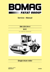
Reviews

There are no reviews yet.

Be the first to review “BOMAG BW 211 D-4 PD-4 BW 213 D-4 PD-4 Single Drum Roller Service Manual – Complete Workshop PDF”

What Our Customers Say

β˜…β˜…β˜…β˜…β˜… Live reviews from customers
Loading customer reviews...
0
    0
    Your Cart
    Your cart is emptyReturn to Shop
    πŸ›’
    Recently Purchased
    πŸ•’ verified order