Description
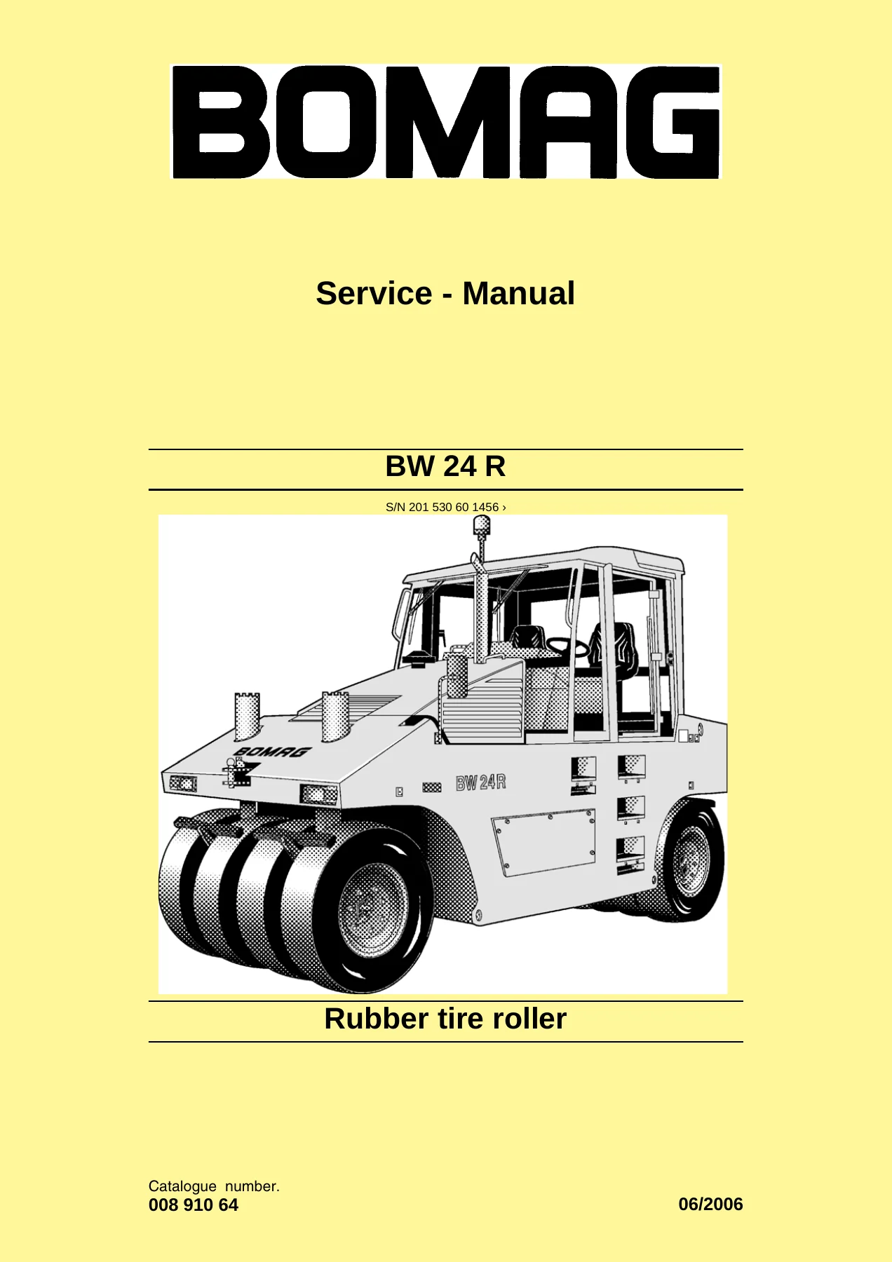
BOMAG BW 24 R Service Manual – Full Workshop Repair Documentation
This is the complete service manual for the BOMAG BW 24 R rubber tire roller, issued under document number 008 910 64. It is the workshop-level reference covering everything from routine technical data and maintenance charts through to full component removal, disassembly, inspection, reassembly and adjustment procedures for the machine’s major assemblies. Every chapter is written for the trained mechanic working on the roller in a workshop environment.
File Details
- Manual type: Service / Workshop Manual
- Brand: BOMAG
- Model: BW 24 R (Rubber tire roller)
- Document number: 008 910 64
- Serial number applicability: from 201 530 60 1456
- Language: English
- File format: PDF
- Page count: 406 pages
- Technical data status date: 2006-04-12
Chapters Covered
- 1 General – Introduction, safety regulations, general repair instructions, tightening torques
- 2 Technical data – Technical data, maintenance chart, table of fuels and lubricants, fuels and lubricants
- 3 Fundamental electrics – Understanding circuit diagrams, terminal designations, current and voltage, resistance, series and parallel connection, Ohm’s law, electrical energy, formula diagram, metrology, diodes/relays/fuses, batteries, three-phase generator, electric starter, Telemeanique switch, inductive proximity switches, Deutsch plugs DT and DTM, spring-clamp plugs and terminals
- 4 Special tools, electrics – Electric test case, multimeter, test prods, measuring lines, magnetic coil tester, clip-on measuring instrument, battery/generator tester, crimping and disassembly tools for Deutsch, ITT, Schaltbau, FCI Burndy and Hirschmann contacts
- 5 Workshop Manual – Speedometer module, removing and installing the engine, rear axle, front axle, drive shaft, steering, service brake, parking brake, wheels
- 6 Suppliers documentation – Spicer Off-Highway T20000 2 & 3 speed inline powershift transmission, differential gear (NAF STA 04 / STA 05)
- 7 Circuit diagrams – Wiring diagram, pneumatic diagram
- 8 Supplement to circuit diagram – Control elements in circuit diagram, monitoring module A15
Complete PDF Bookmark Tree
Complete Bookmarks
The complete bookmarks in the βBOMAG BW 24 R Rubber Tire Roller Service Manual – PDF Workshop Repair Guideβ are as follows:
+BW 24 Rp. 1
S/N 201 530 60 1456 βΊp. 1
+Rubber tire rollerp. 1
+1.1 Introductionp. 6
they enable the customer/user to exactly calculate the running times and the completion of projects within the specified time.p. 6
in the rental business machines can be reliably used and planned, so that the number of stock machines can be kept at a low level.p. 6
for the manufacturer satisfied customers provide a good image and give a feeling of confidence.p. 6
the location of components in the machine eases maintenance work,p. 6
the high quality standard of BOMAG is the basis for the considerable extension of the service and maintenance intervals.p. 6
the After Sales Service of BOMAG, including excellent operating and maintenance instruction manuals, high quality training cours…p. 6
1 Operating and maintenance instructionsp. 6
2 Spare parts cataloguep. 6
3 Wiring diagram*p. 6
4 Hydraulic diagram*p. 6
5 Service Informationp. 6
+Safety regulationsp. 7
Important notesp. 7
+Generalp. 7
Before starting repair work stand the machine on level and solid ground.p. 7
Always secure the machine against unintended rolling.p. 7
Secure the engine reliably against unintentional starting.p. 7
Mark a machine that is defective or being repaired by attaching a clearly visible warning tag to the steering wheel.p. 7
On machines with articulated joint keep the articulated joint locked during work.p. 7
Use protective clothes like hard hat, safety boots and gloves.p. 7
Keep unauthorized persons away from the machine during repair work.p. 7
Tools, lifting gear, lifting tackle, supports and other auxiliary equipment must be fully functional and in safe condition.p. 7
Use only safe and approved lifting gear of sifficient load bearing capacity to remove and install parts or components from and to the machine.p. 7
Be careful with cleansing agents. Do not use easily inflammable or harmful substances, such as gasoline or paint thinners for cleaning.p. 7
Cleaning or repair work on the fuel tank is very dangerous. Do not smoke or allow any ignitable sparks or open fire in the vicinity when cleaning or repairing a tank. .p. 7
When performing welding work strictly comply with the respective welding instructions.p. 7
+Special safety regulationsp. 7
Use only genuine BOMAG spare parts for repair purposes. Original parts and accessories have been specially designed for this machine.p. 7
We wish to make explicitly clear that we have not tested or approved any parts or accessories not supplied by us. The installati…p. 7
Unauthorized changes to the machine are prohibited for safety reasons.p. 7
If tests on the articulated joint need to be performed with the engine running, do not stand in the articulation area of the machine, danger of injury!p. 7
Do not perform cleaning work while the engine is running.p. 7
If tests must be performed with the engine running do not touch rotating parts of the engine, danger of injury.p. 7
Exhaust gases are highly dangerous. Always ensure an adequate supply of fresh air when starting the engine in closed rooms.p. 7
Refuel only with the engine shut down. Ensure strict cleanliness and do not spill any fuel.p. 7
Keep used filters in a separate waste container and dispose of environmentally.p. 7
Dispose of oils and fuel environmentally when performing repair or maintenance work.p. 7
Do not refuel in closed rooms.p. 7
Do not heat up oil higher than 160 ΛC because it may ignite.p. 7
Wipe off spilled oil and fuel.p. 7
Do not smoke when refuelling or when checking the acid level in the battery.p. 8
Do not check the acid level of the battery with a naked flame, danger of explosion!p. 8
Old batteries contain lead and must be properly disposed of.p. 8
There is a danger of scalding when draining off engine or hydraulic oil at operating temperature.p. 8
on machines with rubber tires a tire may busr if incorrectly assembled. This can cause severe injury.p. 8
Do not exceed the specified highest permissible tire pressure.p. 8
+Hydraulicsp. 8
Hydraulic oil escaping under pressure can penetrate the skin and cause severe injury. You should therefore relieve the pressure in the system before disconnecting any lines.p. 8
Before applying pressure to the system make sure that all line connections and ports have been properly tightened and are in perfect condition.p. 8
Hydraulic oil leaking out of a small opening can hardly be noticed, therefore please use a piece of cardboard or wood when check…p. 8
Do not step in front of or behind the drums/wheels/ crawler tracks when performing adjustment work in the hydraulic system while the engine is running. Block drums and/or wheels / crawler tracks with wedges.p. 8
+Air conditioning systemp. 8
When opening refrigerant containers the contents may escape in liquid or vaporous state. The higher the pressure in the containe…p. 8
In a refrigerant container there must be a steam space above the liquid space. The liquid expands with increasing temperature. T…p. 8
In case of occurring mechanical damage or corrosion on the refrigerant container, the container must be replaced, in order to prevent it from bursting and causing further damage.p. 8
Since the fluid container is pressurized, the manufacture and testing of these pressure vessels is governed by the pressure vess…p. 8
Wear safety goggles! Put on your safety goggles. This will protect your eyes against coming into contact with refrigerant, which could cause severe damage by freezing.p. 8
Wear safety gloves and an apron! Refrigerant are excellent solvents for greases and oils. In contact with skin they will remove the protective grease film. However, degreased skin is very sensitive against cold temperatures and germs.p. 8
Do not allow liquid refrigerants to come into contact with skin! Refrigerant takes the heat required for evaporation from the en…p. 8
Do not inhale higher concentrations of refrigerant vapours! Escaping refrigerant vapours will mix with the ambient air and displace the oxygen required for breathing.p. 9
Smoking is strictly prohibited! Refrigerants may be decomposed by a glowing cigarette. The resulting substances are highly toxic and must not be inhaled.p. 9
Welding and soldering on refrigeration equipment! Before starting welding or soldering work on vehicles, (in the vicinity of air…p. 9
Pungent smell! In case of a pungent smell the afore mentioned decomposition products have already been created. Extreme care must be exercised not to inhale these substances, as otherwise the respiratory system, the lungs and other organs may be harmed.p. 9
When blowing out components with compressed air and nitrogen the gas mixture escaping from the components must be extracted via suitable exhaust facilities (workshop exhaust systems).p. 9
Secure pressure vessels against tipping over or rolling awayp. 9
Do not throw pressure vessels. Pressure vessels may thereby be deformed to such an extent, that they will crack. The sudden evap…p. 9
Refrigerant bottles must never be placed near heating radiators. Higher temperatures will cause higher pressures, whereby the pe…p. 9
Do not heat up refrigerant bottles with an open flame. Excessive temperatures can damage the material and cause the decomposition of refrigerant.p. 9
Close empty vessels to avoid the diffusion of moisture.p. 9
Do not overfill refrigerant bottles, since any temperature increase will cause enormous pressures.p. 9
+General repair instructionsp. 10
+Generalp. 10
Before removing or disassembling and parts, hoses or components mark these parts for easier assembly.p. 10
Before assembly oil or grease all parts, as far as this is necessary.p. 10
+Hydraulic systemp. 10
Clean fittings, filler covers and the area around such parts before disassembly to avoid entering of dirt.p. 10
Before disconnecting hoses, pipes or similar relieve the system pressure with the engine shut down.p. 10
During repair work keep all openings closed with clean plastic plugs and caps.p. 10
Do not run pumps and motors without oil.p. 10
When cleaning hydraulic components take care not to damage any fine machine surfaces.p. 10
Chemical and rubber soluble cleansing agents may only be used to clean metal parts. Do not use such substances to clean seals and gaskets.p. 10
Rinse of cleaned parts thoroughly, dry them with compressed air and apply anti-corrosion oil immediately. Do not install parts that show traces of corrosion.p. 10
Avoid the formation of rust on fine machined caused by hand sweat.p. 10
Grease must not used as a sliding agent for assembly work. Use hydraulic oil.p. 10
Do not start the engine after the hydraulic oil has been drained off.p. 10
Use only the specified pressure gauges. Risk of damaging the pressure gauges under too high pressure.p. 10
Clean ports and fittings before removal so that no dirt can enter into the hydraulic system.p. 10
Check the hydraulic oil level before and after the work.p. 10
Use only clean oil according to specification.p. 10
Check the hydraulic system for leaks, find and rectify the cause.p. 10
Fill new hydraulic units with hydraulic oil before starting operation.p. 10
After changing a component thoroughly flush and bleed the entire hydraulic system.p. 10
Perform measurements at operating temperature of the hydraulic oil (approx. 40 ΛC).p. 10
After changing a component perform a high and charge pressure test, if necessary check the speed of the exciter shaft.p. 10
The operating pressure of the exciter shaft to a great extent depends on the base under the vibrating drum. If the soil is too hard place the drums on old rubber tires. Do not activate the vibration on a hard, concreted base, danger of bearing damage.p. 10
After the completion of all tests perform a test run and then check all connections and fittings for leaks with the engine still stopped and the hydraulic system depressurized.p. 10
After changing a component clean the hydraulic oil tank thoroughly.p. 10
Fill the housings of hydraulic pumps and motors with hydraulic oil.p. 10
Use only hydraulic oils according to the specification in the maintenance instructions.p. 10
After changing a component clean the hydraulic system as described in the flushing instructions in order to prevent all other components from being damaged by abrasion and metal chips remaining in the system.p. 10
Change the hydraulic oil filter.p. 10
Bleed the hydraulic circuits.p. 10
Start up the system without load.p. 10
Check the hydraulic oil level in the tank, fill up oil if necessary.p. 10
Check system pressures and speeds.p. 10
Check fittings and flanges for leaks.p. 10
After each repair check all adjustment data, rotational speeds and nominal values in the hydraulic system, adjust if necessary.p. 10
Do not adjust pressure relief valves and control valves to values above their specified values.p. 10
+Seals and gasketsp. 10
Generally use new seals and gaskets when performing assembly work. The required seal kits are available as spare parts.p. 10
+Electricsp. 11
In approx. 10 % of the examined cases the problems were caused by control units.p. 11
In approx. 15 % sensors and actuators were the cause of the problems.p. 11
Before changing any expensive components, such as control units, you should run a systematic trouble shooting session to elimina…p. 11
Check for good cable and ground contacts, therefore keep all mechanical transition points between electric conductors (terminals, plugs) free of oxide and dirt, as far as this is possible.p. 11
Perform trouble shooting in a systematic way. Do not become confused by the high number and variety of electric cables, current …p. 11
Surge voltages in the electric system must be strictly avoided: For electric and inert gas welding all electric components, batt…p. 11
Do not disconnect or connect battery or generator while the engine is running. Do not operate the main battery switch under load. Do not use jump leads after the battery has been removed.p. 11
Sensors and electric actuators on control units must never be connected individually or between external power sources for the p…p. 11
Even with an existing polarity reversal protection incorrect polarity must be strictly avoided. Incorrect polarity can cause damage to control units!p. 11
Plug-in connectors on control units are only dust and water tight if the mating connector is plugged on! Control units must be protected against spray water, until the mating connector is finally plugged on!p. 11
Disconnecting the control unit plug connectors with the control unit switched on, i.e. with the power supply (terminal 15 "On"), is not permitted. Switch the voltage supply "off" first – then pull out the plug.p. 11
+Air conditioning systemp. 11
In case of a repair on the refrigeration system you should first evacuate the air conditioning system for at least 45 minutes to…p. 12
During repair work on refrigerant lines and components, these must be kept closed as far as possible, in order to prevent the in…p. 12
Make sure that no dirt or foreign parts can enter into the compressor or the air conditioning system. The area around the refrigerant hoses should be cleaned with a gasoline free solvent.p. 12
All parts to be reused should be cleaned with a gasoline free solvent and blow-dried with clean compressed air or dried with a lint-free cloth.p. 12
Before opening all components should have warmed up to ambient temperature, to avoid that damp air is drawn into the component by the difference in temperatures.p. 12
Damaged or leaking parts of the air conditioning must not be repaired by welding or soldering, but must generally be replaced.p. 12
Do not fill up refrigerant, but extract existing refrigerant and refill the system.p. 12
Different types of refrigerant must not be mixed. Only the refrigerant specified for the corresponding air conditioning system must be used.p. 12
Refrigerant circuits with refrigerant type R134a must only be operated with the compressor oil / refrigeration oil approved for the compressor.p. 12
Used compressor oil / refrigeration oil must be disposed of as hazardous waste.p. 12
Due to its chemical properties compressor oil / refrigeration oil must never be disposed of together with engine or transmission oil.p. 12
Compressor oil / refrigeration oil is highly hydroscopic. Oil cans must strictly be kept closed until use. Oil rests should not be used, if the can had been opened over a longer period of time.p. 12
All O-rings as well as pipe and hose fittings must be oiled withcompressor oil / refrigeration oilibefore assembly.p. 12
When replacing a heat exchanger, e.g. evaporator or condenser, any compressor oil / refrigeration oil lost by exchanging the components, must be replaced with fresh oil.p. 12
A too high compressor oil / refrigeration oil level adversely affects the cooling performance and a too low oil level has a negative effect on the lifetime of the compressor.p. 12
If a air conditioning unit needs to be opened, the dryer must be replaced in any case.p. 12
Always use new O-rings when reassembling the unit.p. 12
Always use two spanners when connecting pipes or hoses, to prevent the pipe end from being damaged.p. 12
Tighten screw fittings with the specified torque.p. 12
Check the connections of pipes, fittings or components thoroughly; do not use if damaged.p. 12
Do not leave the refrigerant circuit unnecessarily open to the atmosphere. Do not attempt to repair bent or burst pipes.p. 12
Compressor valves must only be opened after the system has been properly sealed.p. 12
The use of leak detection colouring matter is not permitted, because its chemical composition is unknown and its effect on compr…p. 12
Tools used on refrigeration circuits must be of excellent condition, thus to avoid the damage of any connections.p. 12
The dryer is to be installed last, after all connections in the refrigerant circuit have been tightened.p. 12
After completion of repair work screw locking caps (with seals) on all connections with valves and on the service connections. Start up of the air conditioning system. Observe the filling capacity.p. 12
Before start up of the air conditioning system after a new filling: – Turn the compressor approx. 10 revolutions by hand using t…p. 12
Never operate the compressor over longer periods of time with high engine speeds without a sufficient amount of refrigerant in the system. This could probably cause overheating and internal damage.p. 12
+Tightening torquesp. 13
Tighten fastening screws and nuts according to the table of tightening torques.p. 13
Tightening torques deviating from the ones in the table are specially mentioned in the repair instructions.p. 13
2 Technical datap. 15
+Technical data
2.2 Maintenance chartp. 20
2.3 Table of fuels and lubricantsp. 22
+2.4 Fuels and lubricantsp. 22
Engine oilp. 22
+Oil viscosityp. 22
Oil qualityp. 23
Lubrication oil change intervalsp. 23
Fuelsp. 23
Winter fuelp. 23
Hydraulic oilp. 23
Oil for powershift transmissionsp. 24
Oil for differential, gear housingsp. 24
Lubrication greasep. 24
Brake fluidp. 24
+Coolantp. 24
3 Fundamental electricsp. 25
+3.1 Understanding circuit diagramsp. 27
Number and type of individual elements in the examined electric circuit, such as plug connectors, fuses, switches, consumers, relays, …p. 27
The sequence in which current flows through the individual elements in the electric circuit.p. 27
Connections between the examined, faulty electric circuit and other circuits in the vehicle wiring system.p. 27
Pin assignment of plug-and-socket connections.p. 27
Table of contentsp. 27
Function groupsp. 27
List of componentsp. 27
+Fig. 3 Table of contentsp. 27
From top (plus potential) to bottom (minus potential).p. 28
From left to right.p. 28
From function group to function group.p. 28
Via cross references for potentials and relays.p. 28
Fig. 4 Function groupsp. 28
Fig. 5 Current pathsp. 29
Fig. 6 List of componentsp. 29
+Fig. 7 Graphic symbolp. 30
1 Current sourcep. 30
2 Conductorp. 30
3 Switchp. 30
4 Groundp. 30
5 Filament lampp. 30
6 Filament lamp with two luminous elementsp. 30
7 Voltmeterp. 30
8 Ampere meterp. 30
9 Resistancep. 30
10 Backupp. 30
11 Line connection (fixed)p. 30
12 Line connection (separable)p. 30
+Fig. 8 Graphic symbolp. 30
1 Diodep. 30
2 Transistorp. 30
3 NPN-Transistorp. 30
4 changeable resistancep. 30
5 Condenserp. 30
6 Working current relayp. 30
3.2 Terminal designationsp. 31
+3.3 Current and voltagep. 35
Generalp. 35
+Voltagep. 35
+Fig. 1p. 35
1 (Fig. 1) Chargep. 35
2 Voltagep. 35
3 Currentp. 35
+Fig. 2p. 35
electric voltage is the pressure or force applied to free electrons.p. 35
the electric voltage is the cause of electric currentp. 35
electric voltage is a result of the equalization attempt of electric charges.p. 35
+Currentp. 36
The charge carriers may either be electrons or ions.p. 36
Electric current can only flow if there is a sufficient amount of free moving charge carriers.p. 36
The higher the number of electrons flowing through a conductor per second, the higher the amperage.p. 36
Fig. 3 Circuitp. 36
+Types of currentp. 36
Fig. 1 Direct current (D.C.)p. 36
Fig. 2 Alternating current (A.C.)p. 36
Fig. 3 Pulsating direct currentp. 36
+Fig. 4 PWMp. 37
The signal voltage cannot be measured.p. 37
The current can be measured.p. 37
+Fig. 5 CANp. 38
Networking of control units for the realization of complex functions.p. 38
Reduction of the extend of wiring and plug connections.p. 38
Better diagnostic possibilities (central diagnostics socket).p. 38
+3.4 Resistancep. 39
+Resistance and voltage dropp. 39
Fig. 1 Various size resistorsp. 39
+Fig. 2 Potentiometer, infinitely adjustable resistorp. 39
The thicker the cable cross-section, the lower the voltage loss.p. 39
The shorter the cable, the better the current.p. 39
The cleaner the contacts, the better the current.p. 39
The quality of the ground cable is of the same importance as the supply line.p. 39
+Unnecessary resistancesp. 39
Fig. 1 Screw-type terminalsp. 39
Fig. 2 Spring clampsp. 39
Fig. 3p. 40
Fig. 4 Balistol oilp. 40
Fig. 5p. 40
+3.5 Series / parallel connectionp. 41
+Fig. 1 Series connectionp. 41
In series connection the plus pole of the first battery must be connected with the minus pole of the second battery.p. 41
The sum of all individual voltages is applied to the free poles.p. 41
The total capacity (Ah) is identical with the capacity of the individual battery.p. 41
All resistances (consumers) are supplied with the same voltage.p. 41
Each of the resistances (consumers) draws as much current as required.p. 41
Fig. 2 Parallel connectionp. 41
+Fig. 3p. 41
In parallel connection the plus pole of the first battery is connected with the plus pole of the second battery and the minus pole of the first battery with the minus pole of the second battery.p. 42
Plus and minus poles have the voltage of the single battery applied.p. 42
The total capacity (Ah) is identical with the sum of all battery capacities.p. 42
+3.6 Ohm's lawp. 42
+3.7 Electrical energyp. 43
+3.8 Formula diagramp. 44
Select the desired value from the inner circle.p. 44
Determine the formula variables in the quarter circlep. 44
Calculatep. 44
Fig. 1p. 44
+3.9 Metrologyp. 45
+Test lampsp. 45
Fig. 1 Test lampp. 45
Fig. 2 Diode test lampp. 45
+Multimeterp. 45
+Fig. 1 Multimeterp. 45
the range selector switch must be correctly set for the corresponding measurement.p. 45
the test cable must be plugged into the correct socket.p. 45
the voltage type (AC/DC) must be set.p. 45
In case of direct voltage the correct polarity must be assured.p. 45
the measuring range should be chosen higher at the beginning of the test.p. 45
In order to avoid any influence on the circuitry to be measured, the internal resistance of the voltage tester should be as high as possible.p. 45
The component to be measured must not be connected to the power supply during the measurement.p. 45
At least one side of the component to be measured must be disconnected from the circuitry, as otherwise the measuring result may be influenced by parallel components.p. 45
Polarity is of no significance.p. 45
+Fig. 2p. 46
The meter is always connected parallel to consumer, component or power source.p. 46
Measurement at the voltage source measures the currently available Voltage.p. 46
A measurement at the consumer measures the voltage drop at this component.p. 46
+Fig. 3p. 46
During the measurement the current must be able to flow through the meter, i.e. the electric circuit must be opened. The meter is connected in series with the consumer.p. 46
+Clip-on measuring instrumentp. 46
+Fig. 1 Clip-on measuring instrumentp. 46
For measuring current the individual conductor must be fully enclosed by the measuring tongs, the actual measurement takes place without contact.p. 46
+Magnet testerp. 47
+Fig. 1 Magnet testerp. 47
The component to be tested does not need to be removed.p. 47
The magnetic coil can also be tested under a protective cap.p. 47
+3.10 Diodes, relays, fusesp. 47
+Diodesp. 47
+Fig. 1p. 47
At 0.6 – 0.7 Volt (silicium diode) the diode becomes conductive.p. 47
The diode does not allow current to pass through.p. 47
+Fig. 2 Marking of the cathodep. 47
For rectifying A.C. voltage.p. 47
For absorbing voltage peaks (free-wheeling diode).p. 47
For construction of logical circuits.p. 47
+Fig. 3 Diode circuitryp. 48
The solenoid valve Y48 (Fig. 3) is supplied with electric current when switch S34 is switched to position "1" or "2".p. 48
Solenoid valve Y20 is supplied, if the switch is in position "1".p. 48
Solenoid valve Y21 is supplied with electric current, when switch S34 is switched to position "1" or "2".p. 48
+Relaysp. 48
Fig. 1 Relaysp. 48
Fig. 2 Relay circuitryp. 48
+Fusesp. 49
+Fig. 1p. 49
approx. 1 hour with 1.5 times the rated currentp. 49
approx. 1 minute with 2.5 times the rated current.p. 49
+3.11 Batteriesp. 49
Fig. 1p. 49
+Fig. 2p. 49
Wear goggles and face protection (acid).p. 50
Wear suitable clothes to protect face, hands and body (acid).p. 50
Work and store accumulators only well ventilated rooms. (Development of oxyhydrogen gas).p. 50
Do not lean over the battery while it is under load, being charged or tested. (Danger of explosion).p. 50
Burning cigarettes, flames or sparks can cause explosion of the accumulatorp. 50
Keep ignition sources away from the battery.p. 50
Always shield eyes and face towards the battery.p. 50
Do not use battery chargers or jump leads without following the operating instructions.p. 50
Keep the cell plugs closed.p. 50
After an accident with acid flush the skin with water and seek medical advice.p. 50
Do not allow children access to batteries.p. 50
When mixing battery fluid always pour acid into water, never vice-versa.p. 50
Remove the battery and store it in a cool, dry and frost protected room.p. 50
Check the open circuit voltage on the battery at regular intervals (at least once every month).p. 50
Recharge immediately if the open circuit voltage has dropped to 12.25 Volt (no rapid charging).p. 50
Is the battery leaking? Can traces of impact, shock or compression be found in the leaking area?p. 50
Check for e.g. incorrect fastening, foreign bodies on the battery mounting surface and similar.p. 50
The cells are filled with diluted sulphuric acid as electrolyte (approx. 25 Vol% sulphuric acid in distilled water), also referr…p. 50
With a lead cell the acid density is therefore a measure for the charge condition. This characteristic is used to determine the …p. 50
1.25 -1.28, open-circuit voltage approx. 12.7 Volt. Battery is charged.p. 50
1.20 -1.24, open circuit voltage approx.12.4 to 12.5 Volt, is 50% discharged. Charging is necessary.p. 50
1.19 and less, open circuit voltage less than 12.3 Volt. Battery is insufficiently charged. Battery needs to be recharged immediately.p. 50
+Fig. 3 Reading the acid levelp. 51
Maximum permissible tolerance between highest and lowest measuring value of the 6 cells: 0.03 kg/ dm3.p. 51
Fig. 4 Battery and generator testerp. 51
Fig. 5 Charge conditionp. 51
+3.12 Three-phase generatorp. 53
+Generalp. 53
Fig. 6 Rotor with claw polesp. 53
Fig. 7 Stator with 3 windingsp. 53
+Fig. 8 3-phase currentp. 53
Incandescent lampsp. 54
Fluorescent lampsp. 54
Glow lampsp. 54
Electric heating elements.p. 54
Electric motorsp. 54
Relaysp. 54
Accumulatorsp. 54
Control unitsp. 54
All electronicsp. 54
Communication equipment.p. 54
+Fig. 9 Governor with diode plate and rectifier diodesp. 54
To maintain the vehicle voltage under any operating conditions below 14.4 V.p. 54
To match the regulator voltage to the temperature.p. 54
Smooth rising of generator current when switching loads (convenience function to avoid jerking of the engine).p. 54
+Checking the generatorp. 55
This can be easily found out by checking whether the charge control light in the dashboard lights up. If the light does not go out, even at higher speeds, there must be a defect on the generator, the regulator, the wiring or the V-belt.p. 55
When the engine is at rest, the charge control light must light up. If not, the lamp may probably be defective. Defects on generator or wiring are obviously also possible.p. 55
Cable connections on the generator OK?p. 55
V-belt OK?p. 55
Generator ground (engine ground) OK?p. 55
Pre-excitation from vehicle electronics OK?p. 55
All plug-and-socket connectors must be free of corrosion and intermittent contact.p. 55
The generator ground connection must be OK.p. 55
During the measurement switch on as many consumers as possible.p. 55
55 Attach the clip-on ammeter around the B+ line.p. 55
56 Gradually increase the engine speed.p. 55
57 The generator current must be at least as high as the total current of all consumers.p. 55
+Fig. 10 Rotorp. 55
Remove the regulator with carbon brush.p. 55
Contact the rotor slip ring with the tester points.p. 55
The resistance should be between 3 and 6 OHM.p. 55
The rotor coils should not have continuity to ground.p. 55
+Fig. 11 Statorp. 55
Measure the resistance of all three coils.p. 55
The coils should not have contact among each other.p. 55
+Fig. 12p. 56
All plug-and-socket connectors must be free of corrosion and intermittent contact.p. 56
The generator ground connection must be OK.p. 56
The battery should be in good condition – the idle speed voltage of the battery should be at least 12.6 Volt.p. 56
If possible switch off all consumers.p. 56
Perform the measurement at raised engine speed.p. 56
+Fig. 13p. 56
All plug-and-socket connectors must be free of corrosion and intermittent contact.p. 56
The generator ground connection must be OK.p. 56
The battery should be in good condition – the idle speed voltage of the battery should be at least 12.6 Volt.p. 56
If possible switch off all consumers.p. 56
Perform the measurement at raised engine speed.p. 56
The voltage (B+) should adjust itself at 13 to 14 Volt.p. 56
If the carbon brush is not connected to ground the regulator is a so-called minus controlled regulator. The exciter winding is p…p. 56
+Fig. 14p. 56
If the carbon brush is connected to ground the regulator is a so-called plus controlled regulator. The exciter winding is positi…p. 56
Fig. 15p. 57
Fig. 16p. 57
Fig. 17p. 57
+3.13 Electric starterp. 58
to accelerate the combustion engine to start speed with lowest possible current consumption.p. 58
establish the gear connection between starter and combustion engine.p. 58
to maintain this connection.p. 58
to switch on the starter current.p. 58
to return the starter pinion to initial position.p. 58
to switch off the starter current.p. 58
+Fig. 1 Electric starterp. 58
1 Pinionp. 58
2 Roller free-wheelingp. 58
3 Steep threadp. 58
4 Guide ringp. 58
5 Spring windingp. 58
6 Armaturep. 58
7 Pole shoep. 58
8 Carbon brushesp. 58
9 Armature brakep. 58
10 Collectorp. 58
11 Magnetic switchp. 58
12 Engagement leverp. 58
Fig. 2 Switching position during engagementp. 59
+Fig. 3 Switching position during startingp. 59
1 Groundp. 59
2 Batteryp. 59
3 Starter switchp. 59
4 Pull-in windingp. 59
5 Holding windingp. 59
6 Exciter windingp. 59
7 Restoring springp. 59
8 Driverp. 59
9 Pinionp. 59
10 Flywheelp. 59
Immobilizer deactivated?p. 59
Ignition switch OK?p. 59
Travel lever in correct position?p. 59
Emergency stop not actuated?p. 59
Battery sufficiently charged?p. 59
Battery poles OK?p. 59
Main battery fuse OK?p. 59
Main battery switch closed?p. 59
Main starter cable (terminal 30) OK?p. 59
Starter control cable (terminal 50) OK, voltage drop?p. 59
Ground cable OK?p. 59
Switching of magnetic switches OK?p. 59
the experience of the specialistp. 59
the failure probability of the component to be tested and the testing effort for the respective part.p. 59
Initiate the starting process and measure the voltage on the pickup solenoid switch (50a). At least 10.8 Volt should be applied.p. 60
When operating the starter switch the magnetic switch must engage in the flywheel ring gear (noticeable clicking sound) and rele…p. 60
Check the wear on the carbon brushes and their contact pressure.p. 60
Check the collector, it must not have electrical contact with the rotor shaft.p. 60
Check the drive pinion for excessive wear.p. 60
The return mechanism should not be tight, if necessary grease amply with silicon grease (Bosch PZ 2 V3) or a comparable grease.p. 60
Measure the resistance of the magnetic switch main contact in disengaged condition. Maximum value 0.2 OHM.p. 60
+3.14 Telemecanique switchp. 61
+Fig. 1p. 61
Normally open contact 23 located on block 2p. 61
Normally open contact 24 located on block 2p. 61
Normally closed contact 12 located on block 1p. 61
Normally closed contact 11 located on block 1p. 61
Normally closed contact 34 located on block 3p. 61
Normally closed contact 33 located on block 3p. 61
Normally closed contact 63 located on block 6p. 61
Normally closed contact 64 located on block 6p. 61
Normally closed contact 43 located on block 4p. 61
Normally closed contact 44 located on block 4p. 61
+Fig. 2p. 61
1 Insert the front element into the bore and open the fastening adapter with the auxiliary switch.p. 61
2 Tighten the screw.p. 61
3 Click the auxiliary switch into place.p. 61
+3.15 Inductive proximity switchesp. 62
Fig. 1p. 62
Fig. 2p. 62
Fig. 3p. 62
+3.16 Deutsch plug, series DT and DTMp. 63
+Generalp. 63
+Fig. 4 Crimp connectionsp. 63
Perform a pull test on each lead, each of the terminals and connections must withstand a pulling force of 45 N without any difficulties.p. 63
+DT Seriesp. 63
Fig. 1 DT plug connectionp. 63
Fig. 2 DT Seriesp. 63
Fig. 3 Sectional drawingp. 63
+Fig. 4p. 64
Insert the contacts through the rubber grommet until they click into place.p. 64
Insert the orange wedge in direction of arrow.p. 64
+Fig. 5p. 64
Pull the orange wedge out with long nose pliers.p. 64
Slightly pull the lead and unlock the interlocking hook with a screw driver.p. 64
Pull the contact out of the socket.p. 64
+DTM Seriesp. 65
Fig. 1 DTM plug connectionp. 65
Fig. 2 DTM Seriesp. 65
Fig. 3 Sectional drawingp. 65
+Fig. 4p. 66
Insert the contacts through the rubber grommet until they click into place.p. 66
Insert the orange wedge, until it clicks into place.p. 66
+Fig. 5p. 66
Pull the orange wedge (interlock) out with long nose pliers.p. 66
Slightly pull the lead and unlock the interlocking hook with a screw driver.p. 66
Pull the contact out of the socket.p. 66
+3.17 Plugs and terminals in spring clamping technologyp. 67
+Generalp. 67
+Connecting terminal for quick repairsp. 67
+Fig. 1 That's how it worksp. 67
Strip 9-10 mm of the lead.p. 67
Open the actuating lever and insert the strand.p. 67
Return the actuating lever to initial position.p. 67
Fig. 2 Connecting clampp. 67
+Fig. 1 That's how it worksp. 68
Insert a screw driver into the actuating opening until it bottoms.p. 68
Strip 9-10 mm of the lead and insert it into the clamp.p. 68
Pull out the screw driver.p. 68
Fig. 2 Test adapterp. 68
+X-COM plug clampp. 69
+Fig. 1 That's how it worksp. 69
Insert a screw driver into the actuating opening until it bottoms.p. 69
Strip 9-10 mm of the lead and insert it into the plug.p. 69
Pull out the screw driver.p. 69
+Fig. 2 X-COM plug with measuring cablep. 69
The most reliable measurements on the plug can be made when using the measuring and connecting cable with 2mm plug (see special tools for electrics).p. 69
Fig. 3 X-COM plug plugged onto the series clampp. 69
4 Special tools, electricsp. 71
+4.1 Special tools, electricsp. 72
+Fig. 1p. 72
1. Electric test casep. 72
+Fig. 2p. 72
+Fig. 3p. 72
3. Test prod black, with flexible insulated shaft and button operated gripper with 4 mm bushing, length 157 mm.p. 72
4. Test prod red, with flexible insulated shaft and button operated gripper with 4 mm bushing, length 157 mm.p. 72
+Fig. 4p. 72
5. Test prod black, with elastic insulated shaft 4 mm bushing, length 97.5 mm.p. 72
6. Test prod red, with elastic insulated shaft 4 mm bushing, length 97.5 mm.p. 72
+Fig. 5p. 73
7. Measuring and connecting lines with 4mm plug, high flexible design, black, length 0.5 m.p. 73
8. Measuring and connecting lines with 4mm plug, high flexible design, black, length 1 m.p. 73
9. Measuring and connecting lines with 4mm plug, high flexible design, black, length 2 m.p. 73
10. Measuring and connecting lines with 4mm plug, high flexible design, red, length 0.5 m.p. 73
11. Measuring and connecting lines with 4mm plug, high flexible design, red, length 1 m.p. 73
12. Measuring and connecting lines with 4mm plug, high flexible design, red, length 2 m.p. 73
+Fig. 6p. 73
13. Measuring and connecting lines with 2 mm plug and gold plated lamella plugs, high flexible design, black, length 300 mm.p. 73
14. Measuring and connecting lines with 2 mm plug and gold plated lamella plugs, high flexible design, black, length 600 mm.p. 73
15. Measuring and connecting lines with 2 mm plug and gold plated lamella plugs, high flexible design, red, length 300 mm.p. 73
16. Measuring and connecting lines with 2 mm plug and gold plated lamella plugs, high flexible design, red, length 600 mm.p. 73
+Fig. 7p. 73
17. Transition plug connector, with 4 mm plug on one side and 2 mm socket on the other, insulated designp. 73
+Fig. 8p. 74
18. Magnetic coil testerp. 74
+Fig. 9p. 74
19. Clip-on measuring instrumentp. 74
+Fig. 10p. 74
20. Battery – generator testerp. 74
+Fig. 11p. 74
21. Cranked screwdriver (Fig. 11) to open spring clamps (Fig. 12).p. 74
+Fig. 12p. 75
22. Testing adapter to measure the signals from the series spring clamps (Wago).p. 75
+Fig. 13p. 75
23. Tool to disassemble the interlocking on Deutsch plugs (series DT and DTM).p. 75
+Fig. 14p. 75
24. Crimping pliers for Deutsch contacts of series DT and DTM, size AWG 20,16 and 12.p. 75
+Fig. 15p. 75
25. Crimping pliers for Deutsch contacts of series HDT, size AWG 6 and 8.p. 75
+Fig. 16p. 76
26. Disassembly tool for Deutsch contacts of series HDP.p. 76
+Fig. 17p. 76
27. Installation tool for ITT crimp contacts of series CA-COM, contact size 15S/16S/15/16.p. 76
+Fig. 18p. 76
28. Disassembly tool for ITT male contacts of series CA-COM, contact size 15S/16S/15/16.p. 76
+Fig. 19p. 76
29. Disassembly tool for ITT female contacts of series CA-COM, contact size 15S/16S/15/16.p. 76
+Fig. 20p. 77
30. Disassembly tool for Schaltbau contacts of series M1, M2.p. 77
+Fig. 21p. 77
31. Crimping pliers for Schaltbau contacts of series M1, M2 with connecting cross-section 0.14 mmΒ· to 6 mmΒ·.p. 77
+Fig. 22p. 77
32. Disassembly tool for FCI Burndy contacts of series TRIM TRIOp. 77
+Fig. 23p. 77
33. Universal pressing pliers with toggle lever transmission and adjustable end pressure for Crimping roller connector 0.14 mmΒ· to 1 mmΒ·.p. 77
+Fig. 24p. 78
34. Precision pressing pliers for non-insulated flat male and female connectors 0.50 mmΒ· to 6 mmΒ·.p. 78
+Fig. 25p. 78
35. Current measurement adapter for Hirschmann plugs.p. 78
+Fig. 26p. 78
36. Voltage measurement adapter for Deutsch plugs, 8-piece (2 to 12 pole).p. 78
+Fig. 27p. 78
37. Current measurement adapter for Deutsch and AMP plugs, 2 pole.p. 78
5 Workshop Manualp. 79
5.1 Speedometer Modulep. 81
5.2 Removing and installing the enginep. 85
5.3 Rear axlep. 93
5.4 Front axlep. 111
5.5 Drive shaftp. 131
5.6 Steeringp. 135
5.7 Service Brakep. 151
5.8 Parking brakep. 165
+5.9 Wheelsp. 169
6 Suppliers documentationp. 175
6.1 Powershift transmissionp. 177
+6.2 Differential gearp. 363
7 Circuit diagramsp. 379
Circuit diagramsp. 380
7.1 Wiring diagramp. 381
+7.2 Pneumatic diagramp. 395
8 Supplement to circuit diagramp. 399
+8.1 Control elements in circuit diagramp. 400
Fig. 28p. 400
Fig. 29p. 402
Fig. 30p. 403
+8.2 Monitoring module A15 in circuit diagramp. 404
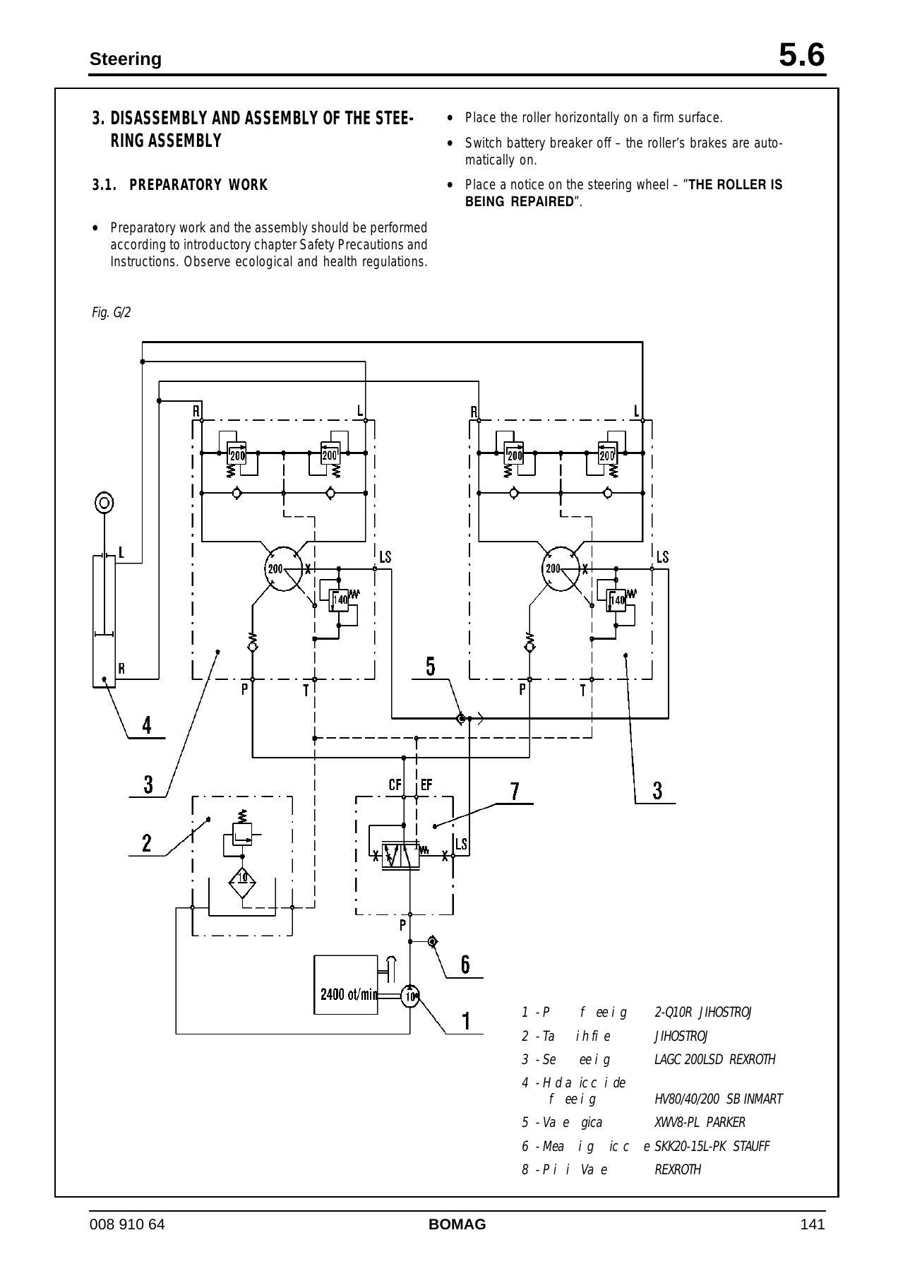
Across those chapters the manual delivers the full working sequence a technician needs for this roller: lifting and securing procedures, torque tables for metric coarse and fine threads, capacities and lubricant specifications, the complete removal and installation route for the Cummins engine, and full strip-down and rebuild instructions for the rear axle drive housing, the front axle fork and guiding pipe, the drive shaft, the steering hydraulic circuit and cylinders, the pneumatic/hydraulic service brake and the spring-applied parking brake. Wiring and pneumatic diagrams are supplied as separate sections, and the Spicer transmission and differential gear documentation is carried through as complete supplier manuals inside the same file.
Key Machine Coverage
Engine and Drivetrain
The engine section covers the Cummins 4BT 4.5C four-cylinder water-cooled diesel rated at 74 kW, including removal with the ROPS frame and cabin, radiator disassembly and assembly, and separation of the engine from the powershift transmission. The Spicer T20000 inline transmission is documented with its converter, pump drive section, directional clutches, range clutches, output section and control valve, along with solenoid logic tables, powerflow diagrams and hydraulic circuit diagrams for neutral, forward and reverse in each speed.
Axles, Brakes and Steering
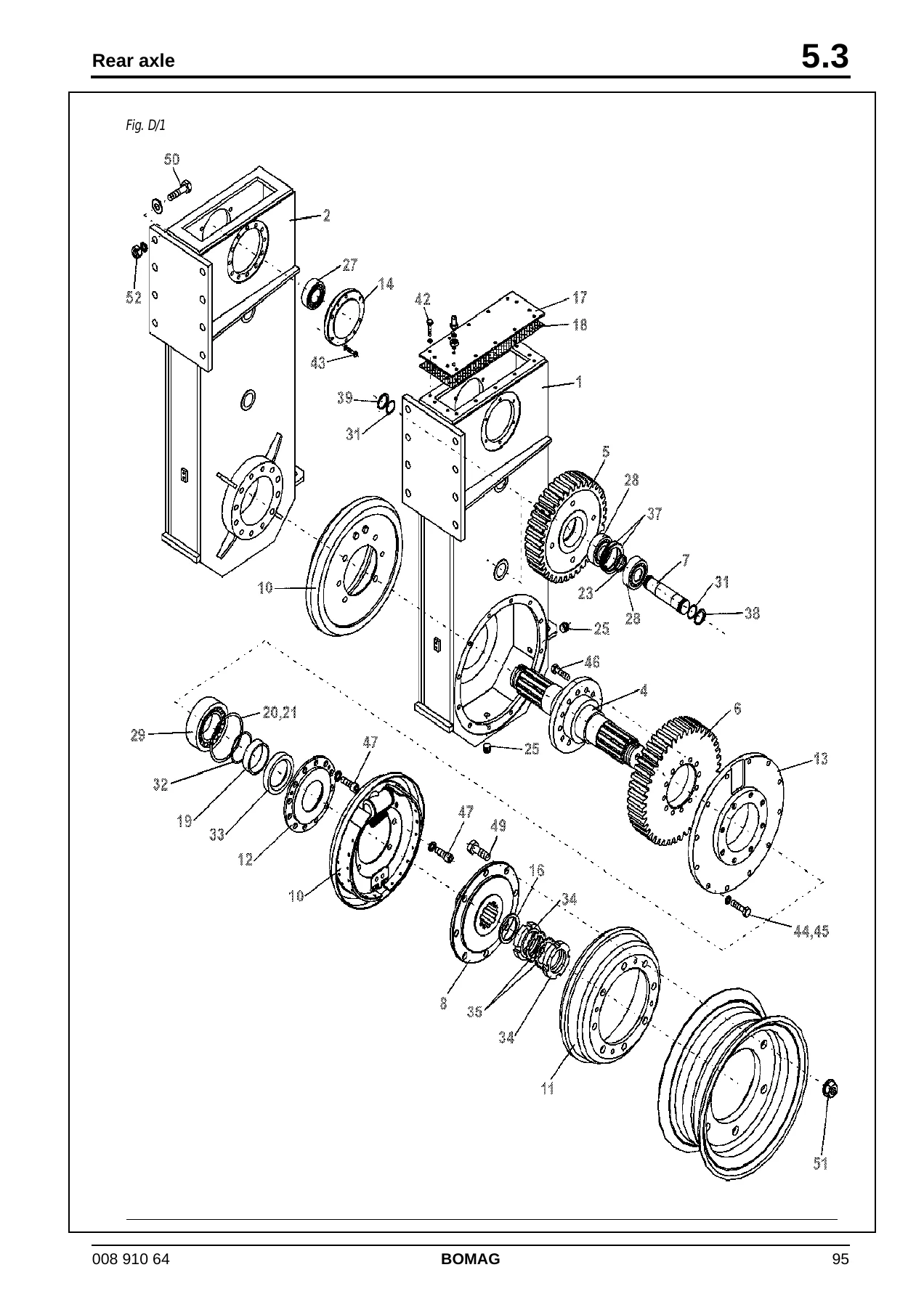
The rear axle chapter breaks down the drive housing, idler gears, bearings and prestress measurement in full, along with brake adjustment on both housings. The front axle chapter covers the guiding pipe, fork, wheel hubs, tapered bearing adjustment, toe-in setting and the complete list of special fixtures. The service brake chapter works through the pedal, booster, brake shoes, venting and brake drum machining limits, while the parking brake chapter deals with the disc brake and the spring-loaded cylinder.
Electrical and Pneumatic Systems
The electrical fundamentals chapter is unusually thorough for a service manual: it teaches circuit diagram reading, DIN 72552 terminal designations, Ohm’s law, series and parallel circuits, diode and relay logic, battery testing, three-phase generator function and testing, and electric starter diagnosis. The wiring diagram, pneumatic diagram and monitoring module supplements complete the electrical picture for the machine.
Who This Manual Is For
This BOMAG BW 24 R service manual suits workshop technicians, fleet maintenance teams, and owner-operators who need the actual repair procedures and specified values rather than a general overview. It is equally useful for preparing a job before the machine is lifted, for checking a torque figure mid-rebuild, and for tracing an electrical fault through the correct wiring diagram.
Get Instant Access to the BW 24 R Workshop Manual
With this manual on hand you can carry out engine removal and installation, strip and rebuild both axles, service and adjust the braking system, diagnose the charging and starting circuits, and work through the Spicer powershift transmission and differential gear with the manufacturer’s own instructions behind you. Correct procedures and specified values are what keep a roller of this size running reliably and prevent repeat failures from guesswork.
The BOMAG BW 24 R service manual is delivered as an instant PDF download after payment. There is no shipping and no waiting – the file opens on any computer, tablet or smartphone and can be printed for use in the workshop.
Reviews
There are no reviews yet.