
Canadair CRJ200 Hydraulic Power Aircraft Maintenance Manual Chapter 29
Original price was: $39.95.$24.95Current price is: $24.95.
The complete Chapter 29 Hydraulic Power section of the Canadair Regional Jet CRJ200 Aircraft Maintenance Manual, covering all three hydraulic systems, pumps, manifolds, reservoirs, accumulators, indicating and every removal, installation, test and inspection task.
Description
The Canadair CRJ200 Hydraulic Power Aircraft Maintenance Manual Chapter 29 is the full hydraulic power section of the Canadair Regional Jet AMM, delivered as one indexed PDF. It documents Hydraulic System No. 1, No. 2 and No. 3 from general description through to component-level removal, installation, adjustment, test, inspection and check procedures, with task numbers, effectivity statements and circuit breaker tables printed against each procedure.
File Details
- Manual type: Aircraft Maintenance Manual (AMM), Chapter 29 — Hydraulic Power
- Manufacturer: Canadair Regional Jet
- Aircraft: CRJ200
- Language: English
- File format: PDF
- Pages: 538
- Chapter: 29 — Hydraulic Power
- Effectivity: ON A/C ALL
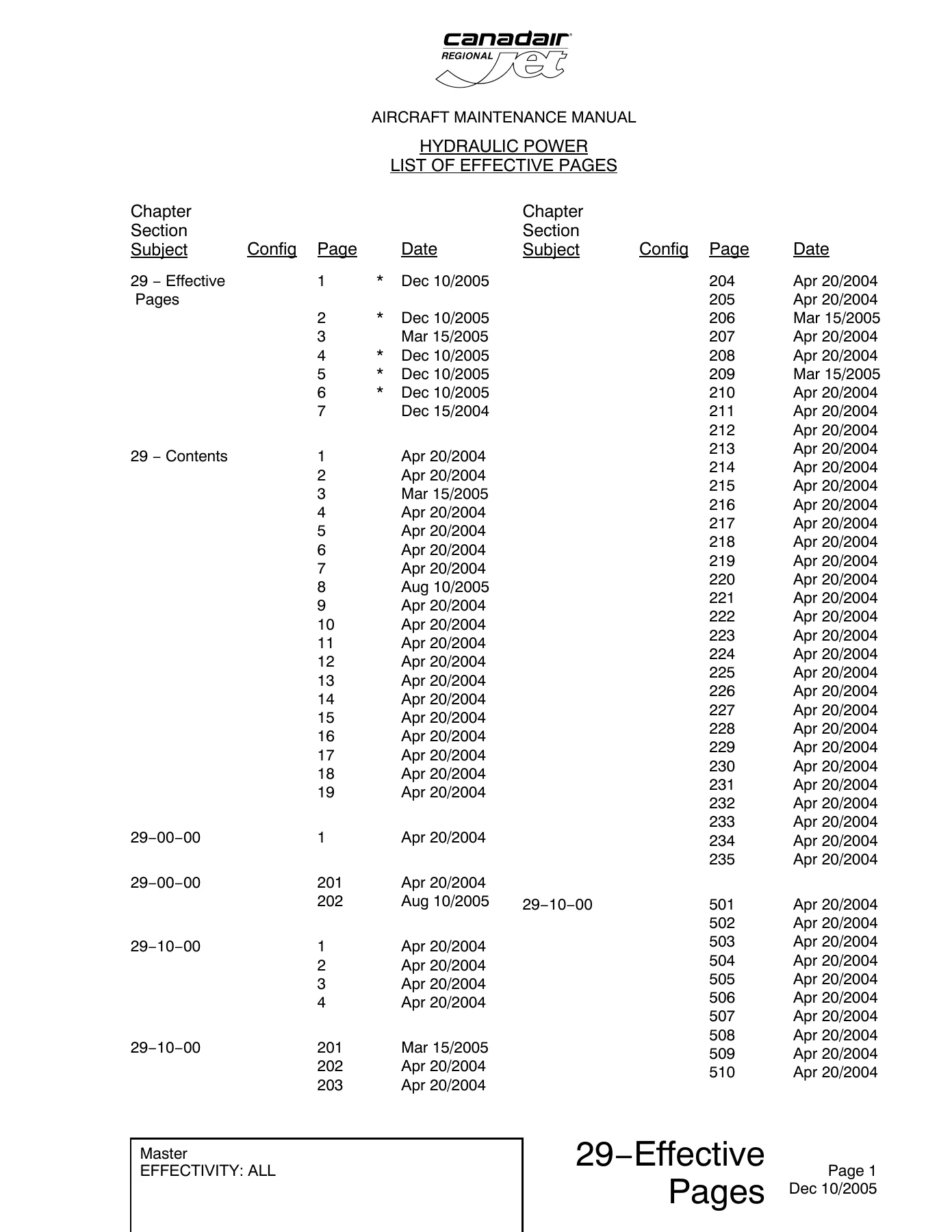
- Revision dates shown: Apr 20/2004, Sep 10/2004, Dec 15/2004, Mar 15/2005, Aug 10/2005, Dec 10/2005, Jan 25/2006 (TR 29-035)
Chapters Covered
- 29-00-00 — General; Hydraulic Safety Precautions
- 29-10-00 — Hydraulics Description and Operation; Drain Reservoirs, Flush and Bleed Systems No. 1, No. 2 and No. 3; Functional Test; Fluid Sample, Acidity, Filter Differential Pressure, Internal and External Leak Checks
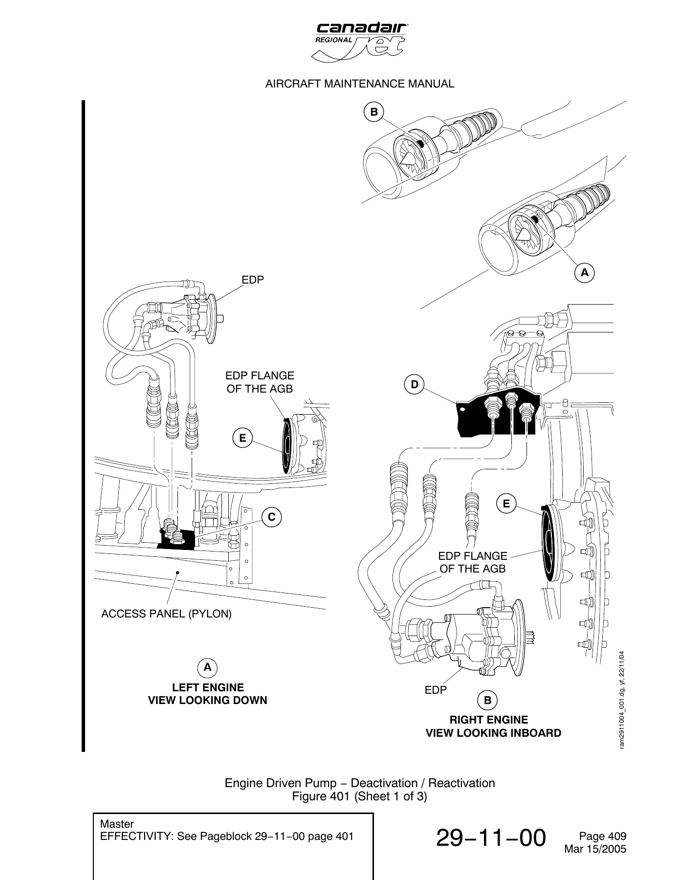
- 29-11-00 — Hydraulic Systems No. 1 and No. 2 Description and Operation; Deactivation of Accumulator Pressure Gauges; Deactivate/Reactivate the EDP
- 29-11-01 — Pump, Engine Driven (EDP) Removal/Installation; Functional Test of the EDP
- 29-11-03 — Pump, Alternating Current Motor (ACMP) Removal/Installation; Operational Test
- 29-11-05 — Assembly, Pressure Manifold Removal/Installation
- 29-11-07 — Relief Valve and Check Valve, Pressure Manifold
- 29-11-09 — Filter Element, Pressure Manifold
- 29-11-11 — Accumulator Assembly; Operational Test of the Accumulators
- 29-11-13 — Gauge, Accumulator Pressure
- 29-11-15 — Ground Service Quick Disconnects
- 29-11-19 — Panel Assembly, Electric Pump Control (ACMP Control Panel)
- 29-11-30 — Hydraulic Fluid Reservoir Assembly — System No. 1
- 29-11-32 — Hydraulic Fluid Reservoir Assembly — System No. 2
- 29-11-33 — Switch, Heat Exchanger Temperature
- 29-11-34 — Reservoir Pressure Relief/Bleed Valve
- 29-11-36 — Hydraulic Shutoff Valve and Firewall Shutoff Valve Electrical Actuator; Operational Test
- 29-11-38 — Case Drain Manifold Assembly
- 29-11-40 — Case Drain Manifold Assembly Filter Element
- 29-11-42 — Heat Exchanger Removal/Installation; Detailed Inspection
- 29-11-44 — Return Manifold Assembly
- 29-11-46 — Return Manifold Filter Element
- 29-11-48 — Overflow Container, Systems No. 1 and No. 2
- 29-11-50 — Check Valves — Return Manifold, Case Drain Manifold and Reservoir
- 29-11-52 — Suction, Pressure and Case Drain Hose Assemblies
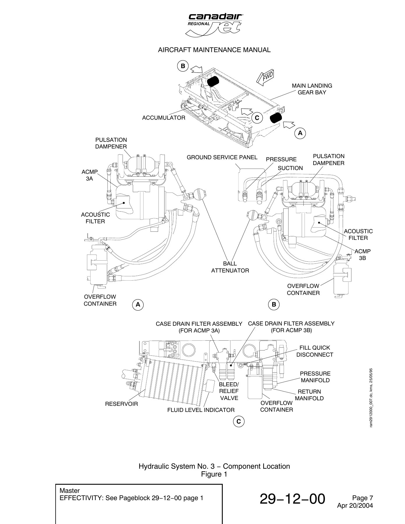
- 29-12-00 — Hydraulic System No. 3 Description and Operation; Deactivation of the Accumulator Pressure Gauge
- 29-12-03 — ACMP, System No. 3 Removal/Installation; Operational Test
- 29-12-05 — Pressure Manifold Assembly, System No. 3
- 29-12-07 — Pressure Manifold Relief Valve, System No. 3
- 29-12-09 — Pressure Manifold Filter Element, System No. 3
- 29-12-11 — Accumulator Assembly, System No. 3; Operational Test
- 29-12-13 — Accumulator Pressure Gauge, System No. 3
- 29-12-17 — Acoustic Filter
- 29-12-19 — Pulsation Dampener
- 29-12-30 — Hydraulic Fluid Reservoir Assembly, System No. 3
- 29-12-32 — Reservoir Pressure Relief/Bleed Valve, System No. 3
- 29-12-34 — Case Drain Manifold Assembly, System No. 3
- 29-12-36 — Case Drain Manifold Assembly Filter Element, System No. 3
- 29-12-38 — Return Manifold Assembly, System No. 3
- 29-12-40 — Return Manifold Filter Element, System No. 3
- 29-12-42 — Overflow Containers, System No. 3
- 29-12-44 — Ground Service Quick Disconnects, System No. 3
- 29-12-46 — Check Valves, System No. 3
- 29-30-00 — Indicating, Description and Operation
- 29-31-01 — Pressure Transducer
- 29-32-01 — Fluid Quantity Transducer/Indicator
- 29-33-01 — Temperature Transducer
- 29-34-01 — Pressure Switch
Read as a whole, this CRJ200 hydraulic manual gives a technician a continuous line from how the three 3000 psi systems are built and routed, through to the exact task number for pulling a pump, flushing a circuit or reading a pressure decay rate. Every procedure carries its own reference information block, its own circuit breaker table with panel, breaker number, name and zone, and its own close-out steps, so the document can be worked from directly at the aircraft rather than treated as background reading.
Three Independent Hydraulic Systems, Documented Separately
Hydraulic System No. 1 draws primary pressure from the engine driven pump mounted on the left (No. 1) engine, identified as EDP 1A, with back-up from ACMP 1B on the left hydraulic rack in the aft equipment compartment. Hydraulic System No. 2 follows the same pattern on the right engine with EDP 2A and ACMP 2B on the right rack. System No. 3 is different — it runs on two alternating current motor pumps, ACMP 3A as the primary generator and ACMP 3B for back-up, both installed in the main landing gear equipment bay, with ACMP 3B capable of running from the air driven generator in an emergency.
The manual documents the full hardware chain for each system: pressure manifold with its internal check valves, pressure switches and pressure transducer; accumulator with nitrogen charging valve and gauge; bootstrap reservoir with quantity transducer, temperature transducer and pressure relief/bleed valve; case drain filter assemblies for each pump; return manifold with bypass valve; heat exchanger with temperature-controlled fan; overflow container; hydraulic shutoff valve in the EDP suction line; and the ground service panel with pressure, return and reservoir fill quick disconnects.
System No. 3 adds the components unique to it — pulsation dampeners and acoustic filters immediately downstream of each ACMP, a 100 cubic inch accumulator, a 690 cubic inch reservoir, three overflow containers, a return fitting with an integral check valve, and ground service connections at the rear fairing of the right wing root.
Maintenance, Test and Inspection Procedures
The maintenance practices block sets out the drain, flush and bleed procedures for all three systems individually, including fill quantities, pressurisation rates, cycle counts for flight spoilers, ground spoilers, ailerons, rudder and elevators, and the landing gear retract/extend cycling required after System No. 3 work. Flush procedures reference the manifold differential pressure indicators that must be watched throughout and the filter elements that may need replacing mid-procedure.
Functional testing is covered for Systems No. 1 and No. 2 together and for System No. 3 separately, with the expected EICAS synoptic page indications listed step by step — reservoir output flow lines changing from blank to green, ACMP output flow lines changing from amber to green, system pressure holding at 3000 ± 200 psi, quantity ranges for each system, temperature limits, brake pressure and the subsystem distribution tables.
Inspection and check tasks include the Level 1 hydraulic fluid inspection with its physical and chemical property limits table, the acidity check using the Skydrol test kit, visual check of the filter differential pressure indicators, internal leak check by pressure decay rate, and a full set of external leak checks — static and dynamic — for the EDP, the ACMP and the reservoir, each with its own permitted leakage rate.
Who This CRJ200 Hydraulic Manual Is For
This chapter suits line and base maintenance engineers working the CRJ200, hydraulic component technicians, technical training departments building course material, and operators who need the manufacturer task data on hand rather than chasing it through a document library. The deactivation and reactivation procedures for the engine driven pump, including the blank-off kit, spline plug, protective caps and V-band coupling torque sequence, are written for an aircraft that has to stay dispatchable, and the MMEL and DDG references appear where they apply.
Put the Correct Procedure in Front of You
Working hydraulic systems on the CRJ200 without the right task card is how seals get cut, lines get cross-threaded and accumulators get charged to the wrong pressure. This Canadair CRJ200 Hydraulic Power Aircraft Maintenance Manual Chapter 29 gives you the removal sequence, the installation sequence, the torque values, the lockwire points, the leak rates that are acceptable and the leak rates that are not, plus the test criteria that confirm the job is actually finished.
IMAGES PREVIEW
Whether you are replacing an engine driven pump, chasing a slow pressure decay, bleeding System No. 3 after a reservoir change, or simply confirming what the EICAS should be showing during a functional test, the answers are in this Chapter 29 document. Download it once and it is yours — instant PDF delivery, no shipping, no waiting, readable on a laptop, tablet or phone in the hangar and printable if you want a paper copy on the bench.
Reviews
There are no reviews yet.