
Case 580N 580SN 580SN-WT 590SN Loader Backhoe Service Manual – Hydraulic Pneumatic Electrical Systems 84393968
Original price was: $39.95.$23.95Current price is: $23.95.
Case 580N, 580SN, 580SN-WT and 590SN loader backhoe service manual covering hydraulic, pneumatic, electrical and electronic systems. Part number 84393968, English, October 2010. Complete repair, diagnostic and specification reference for the hydraulic pump, control valves, accumulators, remote valves, wiring harnesses, alternator and battery.
Description
Case 580N, 580SN, 580SN-WT & 590SN Loader Backhoe Service Manual — Hydraulic, Pneumatic & Electrical Systems
This Case 580N, 580SN, 580SN-WT and 590SN Loader Backhoe Service Manual covers the hydraulic, pneumatic, electrical and electronic systems on these machines. Published under part number 84393968 in October 2010, the manual is written for technicians and owners who need factory-derived procedures, specifications, pressure settings, torque values, capacities and diagnostic flowcharts in one document. It is not a generic overview — it is the full service reference for the hydraulic, pneumatic and electrical systems on all four models.
File Details
- Manual type: Service Manual (Hydraulic, Pneumatic, Electrical & Electronic Systems)
- Brand: Case
- Models covered: 580N, 580SN, 580SN-WT, 590SN Loader Backhoe
- Language: English
- Page count: 399
- File format: PDF
- Document number: 84393968
- Date: October 2010
Chapters and Sections Covered
- Introduction — Safety rules
- Battery — Basic instructions
- Electronic system — Basic instructions
- Heater — Basic instructions
- Basic instructions — Raising and supporting loader lift arms, hood opening and closing
- Torque — Decimal hardware (Grade 5 and Grade 8), metric hardware (Grade 8.8, 10.9, 12.9), steel hydraulic fittings, 37° flare, O-ring boss, O-ring face seal, split flange
- Abbreviation Measurements — Metric and imperial unit conversion reference
- Capacities — Engine crankcase, fuel tank, cooling system, hydraulic system, transmission, front drive axle, rear axle
- Consumables — Engine oil, diesel fuel, dye and black light leak detection kit
- PRIMARY HYDRAULIC POWER SYSTEM (10.A) — Technical data, special tools, general specification, accumulator ride control specification
- PRIMARY HYDRAULIC POWER SYSTEM — Functional data: exploded views, hydraulic gear pump, seal, regulated manifold schematic, regulated manifold exploded view, remote valve component diagram, pilot control color codes, relief valve drawing, hydraulic pump sectional views, output test hose connections, filter sectional view, accumulator exploded and detailed views, ride control solenoid valve, boom lock solenoid valve
- PRIMARY HYDRAULIC POWER SYSTEM — Service: disassemble and assemble regulated manifold, machine preparation, pressure test (pilot manifold, backhoe relief), flow test (pump efficiency), leakage tests (loader control valve, backhoe control valve), pressure test (steering and bucket lock valve flow), leakage test (steering and bucket lock valve), flow test (backhoe valve flow regulator), pressure test (low pressure standby regulator 1 and 2), flowmeter check sheet
- PRIMARY HYDRAULIC POWER SYSTEM — Remote valve: remove and install remote control valves, loader control valve, clam control pilot valve, pilot controls backhoe valve, mechanical controls backhoe valve, check pilot control unit
- PRIMARY HYDRAULIC POWER SYSTEM — Relief valve: adjust main relief valve, remove circuit relief valve, pressure test main relief valve, pressure test and adjust load sense relief valve, replace load sense relief valve
- PRIMARY HYDRAULIC POWER SYSTEM — Hydraulic pump: remove and install 580N, 580SN, 590SN, 580SN-WT, disassemble and inspect load sensor, disassemble, inspect and assemble pump
- PRIMARY HYDRAULIC POWER SYSTEM — Accumulator: check ride control, charging and discharging ride control, disassemble, inspect and assemble, pressure test right solenoid valve, checking nitrogen charge, charging with dry nitrogen
- PRIMARY HYDRAULIC POWER SYSTEM — Control valve: cleaning, disassemble and assemble ride control solenoid valve, disassemble, inspect and assemble boom lock solenoid valve
- PRIMARY HYDRAULIC POWER SYSTEM — Diagnostic: testing problems in a loader circuit, 4×1 clam circuit, single function will not work independently, noise from backhoe hydraulic system, all pilot controls stop working, pilot pattern change does not function, fault codes for pilot controller, hydraulic pump testing, hydraulic oil reservoir testing
- SECONDARY HYDRAULIC POWER SYSTEM (12.A) — Technical data, coupler special tools
- SECONDARY HYDRAULIC POWER SYSTEM — Functional data: exploded view Extendahoe, Extendahoe hose routing, coupler hose routing, coupler cylinder, quick coupler cylinder, swing dampening valve, sectional view backhoe and loader quick coupler single valve, dual valve
- SECONDARY HYDRAULIC POWER SYSTEM — Service: remove and install hydraulic backhoe quick coupler, disassemble, inspect and assemble quick coupler cylinder
- SECONDARY HYDRAULIC POWER SYSTEM — Remote valve: disassemble, inspect and assemble swing dampening valve, check swing cushion valve (swing drift troubleshooting)
- ELECTRICAL POWER SYSTEM (30.A) — Technical data, wiring harness general specification (580N only)
- ELECTRICAL POWER SYSTEM — Functional data: connector component diagrams 01 through 21 covering side console harness, front console harness, chassis harness, cab rear lights harness, front lights canopy harness, hydraulic filter restriction jumper harness, cab B-post harness, C-post harness, combo aux harnesses, A-post harnesses, rear lights canopy harness, pilot controls harness, front lights cab harness, power shift jumper harness, side console SPS/PWR trans HPCR harness
- ELECTRICAL POWER SYSTEM — Wiring harness electrical schematics frames 01 through 26: power distribution/charging, starting, grounding, engine control, powershift transmission inputs, hydraulics, pilot controls, front exterior lights, interior lighting, windshield wipers, instrument cluster, power points, SAHR park brake, HVAC, radio, rear exterior lights, options, horn, comfort steer/ride control, canopy exterior lights, powershift transmission jumper harness, Trax SPS/PS controller, hydraulic heavy lift, combo hydraulics, pilot controls input, DIA kits
- ELECTRICAL POWER SYSTEM — Service: alternator remove and install, battery service instruction, inspect and clean, test, charging, preparing a dry charged battery for use
Across these sections the manual provides the working technician with a full hydraulic, pneumatic, electrical and electronic service reference for the 580N, 580SN, 580SN-WT and 590SN loader backhoes. It begins with the safety rules, battery and electronic system basics, torque tables, abbreviations and machine capacities that apply across the whole machine, then moves into the three major system groups. The hydraulic content covers component identification, removal and installation, disassembly, inspection, assembly, pressure and flow testing, leakage testing and diagnostic flowcharts for every major hydraulic circuit. The electrical content covers the connector layouts for each harness on the machine, pinout tables, and full electrical schematics for every circuit from power distribution and starting through to the pilot controls, heavy lift and DIA kits, followed by alternator and battery service.
What This Case Loader Backhoe Service Manual Helps You Do
Whether you are servicing your own 580N or running a repair shop that sees 580SN, 580SN-WT and 590SN machines, this manual gives you the numbered procedures, the pressure settings, the torque values and the diagnostic charts needed to work on the hydraulic and electrical systems correctly. It covers the primary hydraulic power system, the secondary hydraulic power system (quick coupler and swing dampening) and the complete electrical power system including every harness connector and schematic.
Hydraulic System Coverage
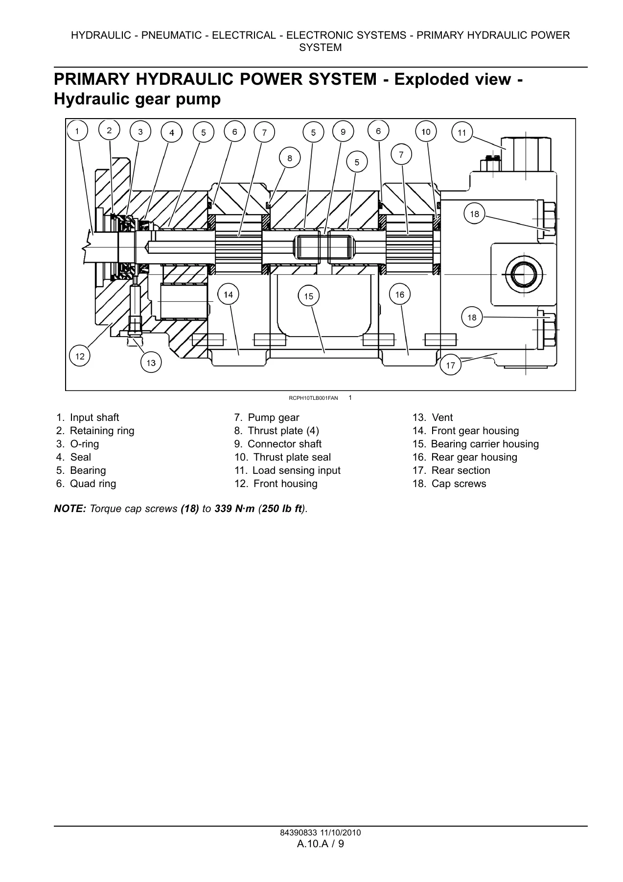
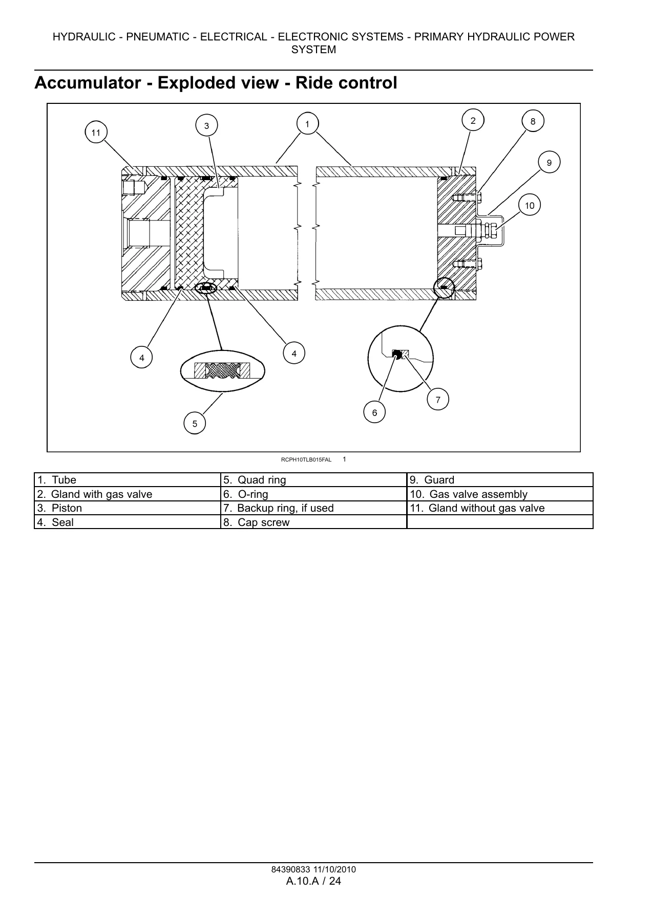
The primary hydraulic power system section is the largest part of the manual. It opens with general specifications for the 580N (Parker P330 single section gear pump, 108 l/min at 231 bar, steering relief 162 bar, main relief 210 bar, accumulator ride control nitrogen charge 25 bar, circuit relief valve settings) and for the 580SN and 580SN-WT (Bosch Rexroth Series 31 variable displacement axial piston pump, HPCO and LS control options, nominal capacity 156.2 l/min, heavy lift capacity 99.3 l/min, HPCO 238 bar, standard main relief 238 bar, heavy lift main relief 250 bar, swing relief 207 bar). It then provides exploded views of the hydraulic gear pump and seal, the regulated manifold and its electrical schematic, remote valve component diagram with pilot control color codes, relief valve drawings, hydraulic pump sectional views for both the 580N and the 580SN/590SN, output test hose connections, filter sectional view, and exploded and detailed views of the ride control accumulator, ride control solenoid valve and boom lock solenoid valve.
Service procedures in this section walk through disassembly and assembly of the regulated manifold, machine preparation for testing, pilot manifold pressure test, backhoe relief pressure test, pump efficiency flow test, loader and backhoe control valve leakage tests, steering and bucket lock valve flow and leakage tests, backhoe valve flow regulator test, low pressure standby regulator tests 1 and 2, and a flowmeter check sheet. Remote valve procedures cover removal and installation of the remote control valves, loader control valve, clam control pilot valve, pilot controls backhoe valve and mechanical controls backhoe valve, plus a pilot control unit check. Relief valve procedures cover adjustment of the main relief valve, removal of the circuit relief valve, pressure testing the main relief valve, pressure testing and adjusting the load sense relief valve and replacing the load sense relief valve. Hydraulic pump procedures cover removal and installation for 580N, 580SN, 590SN and 580SN-WT, load sensor disassembly, inspection and assembly, and full pump disassembly, inspection and assembly. Accumulator procedures cover ride control checking, charging, discharging, disassembly, inspection, assembly, right solenoid valve pressure test, checking the nitrogen charge and charging with dry nitrogen. Control valve procedures cover cleaning, ride control solenoid valve disassembly and assembly, and boom lock solenoid valve disassembly, inspection and assembly. Diagnostic flowcharts cover loader circuit problems, 4×1 clam circuit problems, single function isolation, backhoe hydraulic noise, all pilot controls stopping, pilot pattern change failure, pilot controller fault codes, hydraulic pump testing and hydraulic oil reservoir testing.
Electrical and Electronic Systems Coverage
The electrical power system section provides the wiring harness general specification for the 580N, then connector component diagrams covering the side console harness, front console harness (SPS/PWR trans, mechanical with options), chassis harness, cab rear lights harness, front lights canopy harness, hydraulic filter restriction jumper harness, cab B-post harness, C-post harness, combo aux mechanical control and pilot control hammer or bi-directional valve harnesses, A-post harnesses, rear lights canopy harness (including the six-light version), pilot controls harness, front lights cab and canopy harnesses, power shift jumper harness and the side console SPS/PWR trans HPCR harness with options. Each connector diagram lists cavity, wire ID and circuit for every pin.
The electrical schematics are presented as frames 01 through 26 and cover power distribution and charging system, starting system, grounding, engine control, powershift transmission inputs, hydraulics, pilot controls, front exterior lights, interior lighting, windshield wipers, instrument cluster, power points, SAHR park brake, HVAC, radio, rear exterior lights, options, horn, comfort steer and ride control, canopy exterior lights, powershift transmission jumper harness, Trax SPS/PS controller, hydraulic heavy lift, combo hydraulics, pilot controls input and DIA kits. Alternator removal and installation procedures are included, along with battery service instruction (electrolyte level, maintenance free and standard batteries), battery inspect and clean, battery test (visual checks, specific gravity check, capacity/load test with temperature correction chart) and battery charging guides for maintenance free and standard batteries.
Specifications, Capacities and Torque Values
The front of the manual contains the shared specification data for the whole machine. Torque tables cover decimal hardware in Grade 5 and Grade 8, metric hardware in Grade 8.8, 10.9 and 12.9, plus steel hydraulic fittings including 37° flare, straight threads with O-ring, split flange mounting bolts, O-ring face seal end and O-ring boss end or lock nut fittings. Capacities are listed for the engine crankcase (13.6 l with filter change), fuel tank (159 l), cooling system (16.1 to 18.0 l depending on model and heater), hydraulic system (total system 106.0 to 137.7 l depending on model and Extendahoe, reservoir 47.1 l with filter change), transmission (manual powershuttle and powershift S-type and H-type), front drive axle two-wheel drive and four-wheel drive, rear axle differential and brake master cylinder. Abbreviation and measurement tables cover area, electricity, force, frequency, length, mass, power, pressure, temperature, time, torque, velocity, volume and flow rate in both metric and imperial units. A dye and black light procedure for detecting oil leaks is included with kit part numbers and dye formulations for engine oil, hydraulic oil and transmission oil. Engine oil and diesel fuel recommendations are also covered.
Safety and Machine Preparation
The manual opens with safety rules covering improper operation, maintenance hazards, pressurized systems and accumulators, plastic and resin parts, welding, cutting and drilling on cast ductile iron parts, and welding preparation steps including disconnecting batteries, alternator terminal wires, instrument cluster, engine control unit (ECU), backhoe pilot controls controller, transmission controller and loader 4-in-1 bucket or auxiliary hydraulics controller. Battery safety covers explosion prevention and hazardous chemicals. Machine preparation instructions cover parking, backhoe transport position, loader bucket placement, neutral controls, hood opening with support strut, engine shutdown and Do Not Operate tag placement. Raising and supporting loader lift arms is covered in detail with the support strut procedure.
Get Instant Access to the Case 580N, 580SN, 580SN-WT and 590SN Service Manual
IMAGES PREVIEW
This Case 580N 580SN 580SN-WT 590SN Loader Backhoe Service Manual (part number 84393968) gives you the complete hydraulic, pneumatic, electrical and electronic systems reference in a single downloadable PDF. With it you can diagnose faults using the factory flowcharts, set pressures and relief valves to the correct specification, torque fasteners to the correct values, trace wiring through every harness connector and schematic, service the hydraulic pump, control valves, accumulators, remote valves, swing dampening valve and quick coupler, and test and charge the battery and alternator correctly. Correct procedures and specifications are what separate a repair that lasts from one that comes back. The manual is delivered as an instant PDF download after payment — no shipping, no waiting, readable on any phone, tablet, laptop or desktop, and printable for the workshop. Keep it on the shop computer or print only the pages you need for the job in front of you.

Reviews
There are no reviews yet.