
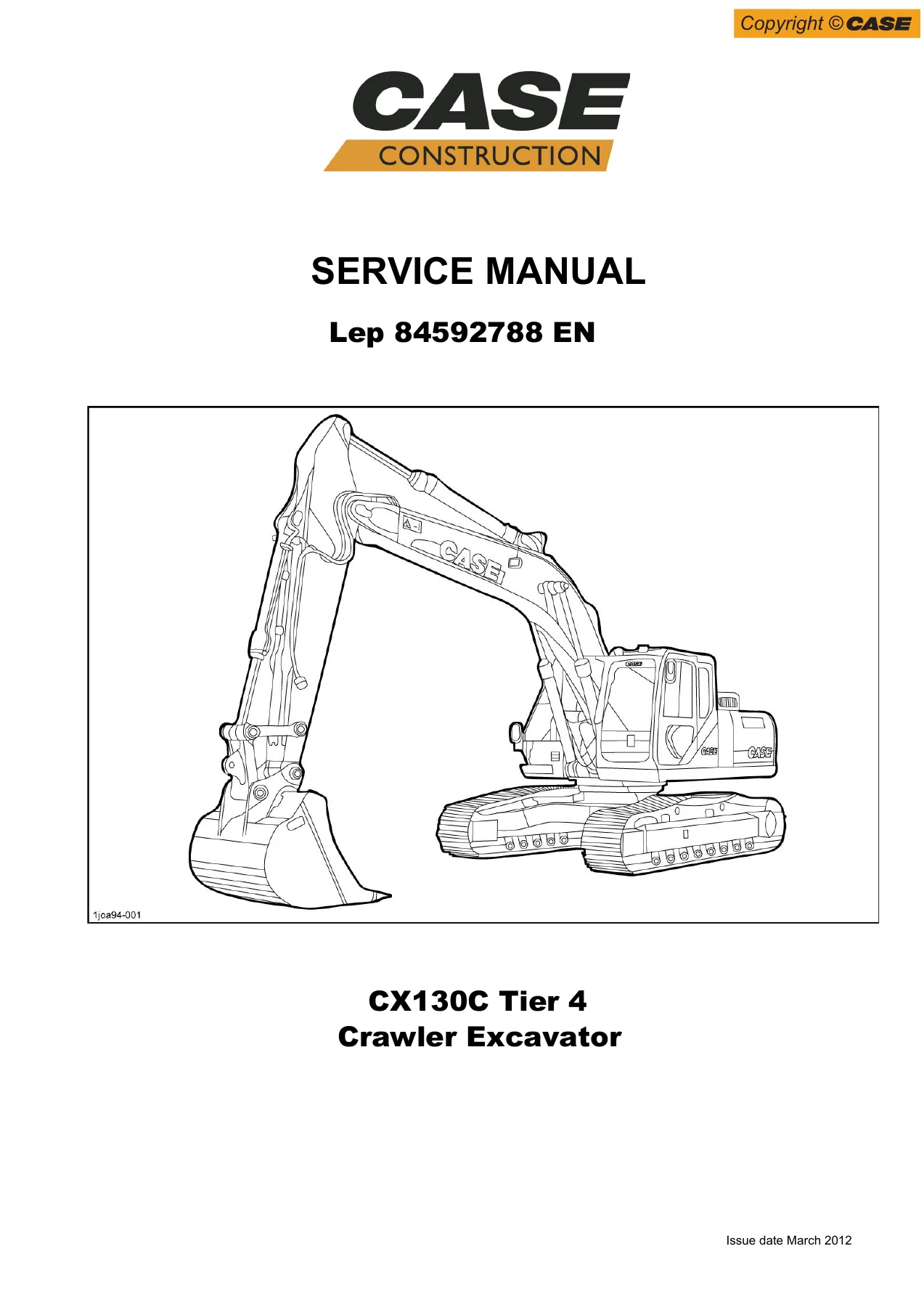

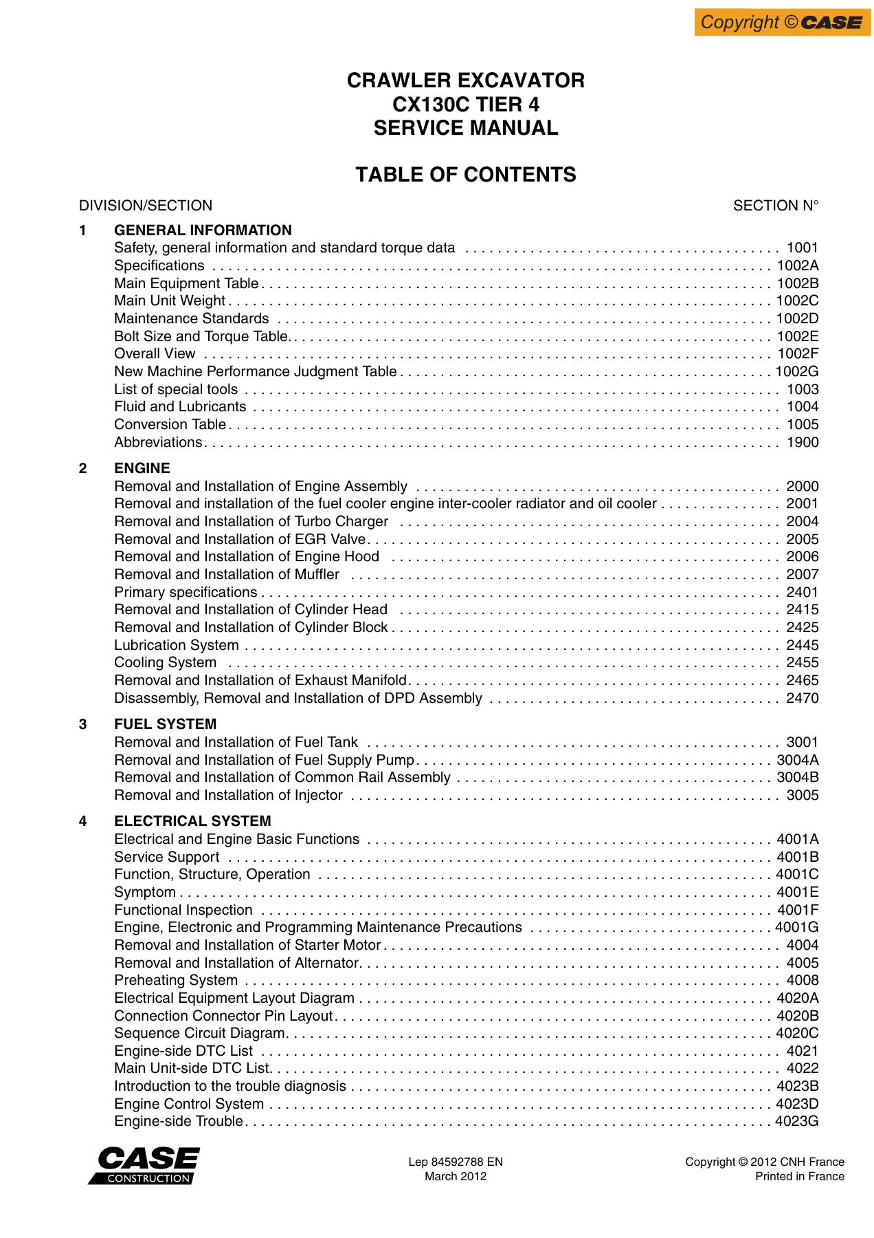
Case CX130C Tier 4 Excavator Service Manual – 84592788 EN
Original price was: $39.95.$24.95Current price is: $24.95.
Complete 1,961-page Case CX130C Tier 4 excavator service manual (84592788 EN) covering hydraulics, travel and swing motors, control valve, cylinders, air conditioner, electrical and hydraulic schematics, with full disassembly, assembly, adjustment and troubleshooting procedures in a printable PDF.
Description
Case CX130C Tier 4 Excavator Service Manual – 84592788 EN
This is the full Case CX130C Tier 4 excavator service manual, published under document number 84592788 EN. At 1,961 pages it is a complete workshop reference covering the machine’s hydraulic, mechanical, electrical and climate-control systems — written for the technician who has to take components apart, measure them, replace wear parts and put them back together to specification.
File Details
- Manual type: Service / repair / workshop manual
- Brand: Case (CNH)
- Model: CX130C Tier 4 excavator
- Document number: 84592788 EN
- Language: English
- Page count: 1,961
- File format: PDF
Chapters Covered
- Tools for Assembly and Disassembly — standard tools, special jigs and secondary materials
- Assembly and Disassembly of Travel Motor — work platform, holder fittings, seal jigs, disassembly and assembly procedures, maintenance standards, troubleshooting
- Removal and Installation of Swing Unit — removal, installation, hydraulic equipment layout
- Assembly and Disassembly of Swing Unit — disassembly, assembly, motor internal structure
- Hydraulic equipment layout — pump chamber, swing body center section, housing left side, cab
- Port diagrams — control valve ports, 4 stack solenoid valve, 2 stack solenoid valve, remote control valves, cushion valve, direction valve, shut-off valve, HBCV, manifolds, swing motor, travel motor, center joint
- Pump P-Q diagram
- Pressure measurement and adjustment procedures — monitor display measurement, gauge installation, relief valve adjustment, pilot pressure, negative control pressure
- Hydraulic pump flow measurement procedures
- Drain volume measurement procedures — travel motor, swing motor
- Air bleed procedure — pump, cylinder, swing motor, travel motor, HBCV
- Removal and Installation of Hydraulic Oil Tank
- Removal and Installation of Hydraulic Pump
- Removal and Installation of Control Valve
- Removal and Installation of Bucket Cylinder, Arm Cylinder, Boom Cylinder
- Removal and Installation of Center Joint
- Removal and Installation of Travel Remote Control Valve and Operation Remote Control Valve
- Removal and Installation of 4 Stack Solenoid and Cushion Valve
- Procedures for Assembly and Disassembly of Hydraulic Pump Main Unit
- Pump Main Unit Maintenance Standards
- Procedures for Assembly and Disassembly of Control Valve — main plunger, foot relief, main relief, overload relief, center bypass, regeneration checks, load holding valve, check valves, swing priority, arm regeneration, travel signal switchover
- Procedures for Operation/Assembly and Disassembly of Hydraulic Cylinder (KYB) — cylinder head, piston, pipe assembly, disassembly, assembly, usage limits
- Procedures for Assembly and Disassembly of Operation Remote Control Valve and Travel Remote Control Valve
- Assembly and Disassembly of Cushion Valve
- Removal and Installation of Arm HBCV and Boom HBCV
- Assembly and Disassembly of Center Joint
- Assembly and Disassembly of Swing Motor
- Explanation of Hydraulic Circuit and Operations (standard model and option) — travel, swing, boom, arm, bucket, negative control, horsepower boost, cushion and heat circuits
- Structure and Operation Explanation of Hydraulic Pump, Travel Motor, Swing Motor, Control Valve, 4 Stack Solenoid Valve, Upper Pilot Valve, Travel Pilot Valve, Cushion Valve
- Removal and Installation of Counterweight, Bucket, Bucket Link, Arm, Boom, Operator’s Seat, Cab Assembly, Wiper, Wiper Controller, Wiper Motor, Monitor, Cab Front Glass, Window Lock
- Tightening torque tables
- Air Conditioner Overall Diagram, disassembly and component replacement — blower motor, blower amp, heater core, heat case, evaporator, expansion valve, motor actuators
- Removal and Installation of Compressor, Condenser, Receiver Dryer
- Work Precautions — refrigerant handling, vacuum operation, gas filling procedures
- Electrical schematic
- Hydraulic schematic
Taken as a whole, this Case CX130C Tier 4 service manual gives a technician the full working reference for the machine: exploded and cross-section views, tightening torques, wear limits, seal and bearing replacement guidance, hydraulic circuit explanations, and step-by-step removal and installation for every major assembly. The disassembly chapters describe the special jigs and holder fittings that make the work safe, the assembly chapters spell out press-fit and preload procedures, and the maintenance standards sections give the reference and permissible limit values used to decide whether a part is reusable. The circuit explanation chapters show how oil is routed during each function — travel, swing, boom, arm, bucket, negative control, horsepower boost and cushion — which is what makes hydraulic fault-finding possible instead of guesswork.
What This Manual Lets You Do
With the Case CX130C Tier 4 service manual on hand you can pull and rebuild the travel motor, drop and strip the swing unit, remove and reseal the hydraulic pump, service the control valve section by section, replace cylinder seals, re-seal the center joint, replace a receiver dryer or condenser and re-charge the air conditioner, and check pressures and flows against the values the manual specifies. It also covers the structural side — counterweight, boom, arm, bucket link, cab and operator’s seat removal — so larger jobs can be planned end to end.
Why Correct Procedures and Specs Matter
The CX130C runs high-pressure hydraulics and precision-finished components. A shim selected from the wrong table during angular ball bearing precompression adjustment, a spool inserted without checking the correct direction, or a seal installed with grease where the manual says none should be used — any of these leads to leaks, short service life or early damage. The precompression adjustment, tightening torque and wear-limit tables in this manual exist precisely to prevent that kind of avoidable failure, and the troubleshooting and maintenance standards sections tell you what to inspect before you decide to replace rather than reuse.
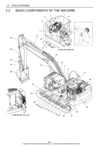
IMAGES PREVIEW
Instant PDF Delivery
The manual is delivered as a downloadable PDF — no shipping, no waiting. Open it on a laptop, tablet or phone in the workshop, print the pages you need for the job in front of you, and keep the full 1,961-page reference on hand for the next one.

Reviews
There are no reviews yet.