
CLAAS ARES 546 556 566 616 626 636 696 Workshop Service Repair Manual PDF
Original price was: $44.95.$26.95Current price is: $26.95.
Comprehensive CLAAS ARES workshop manual covering ARES 546, 556, 566, 616, 626, 636 and 696 tractors. Includes engine and injection service, gearbox repairs, hydraulic systems, axles, brakes, PTO, electrical schematics, electronic controls, diagnostics, adjustments and detailed workshop procedures.
Description
CLAAS ARES 546 556 566 616 626 636 696 Workshop Service Repair Manual PDF
This extensive workshop reference covers the CLAAS ARES 546, 556, 566, 616, 626, 636 and 696 tractors and the major mechanical, hydraulic, electrical and electronic systems used across these models. The CLAAS ARES 546 556 566 616 626 636 696 Workshop Service Repair Manual PDF combines Tier I and Tier II engine information with detailed repair procedures for the transmission, rear and front axles, braking systems, hydraulics, power take-off equipment and tractor electronics.
The manual is arranged as a large multi-chapter workshop reference rather than a basic operator guide. It provides identification information, operating principles, specifications, tightening torques, dimensional data, removal and installation sequences, checks and adjustments, hydraulic measurement points, electrical tests, diagnostic sheets, error-code information and special-tool references. Numerous exploded views, component drawings, circuit diagrams and step-by-step illustrations support the written procedures.
File Details
- Manual type: Workshop Manual
- Brand: CLAAS
- Models: ARES 546, ARES 556, ARES 566, ARES 616, ARES 626, ARES 636, ARES 696
- Language: English
- Pages: 1253
- File format: PDF
- Document references shown: 60 05 029 693 and 60 05 029 904
- Document dates shown: 10.2003 and 01.2004
Engine, Fuel Injection and Mechanical Repair Coverage
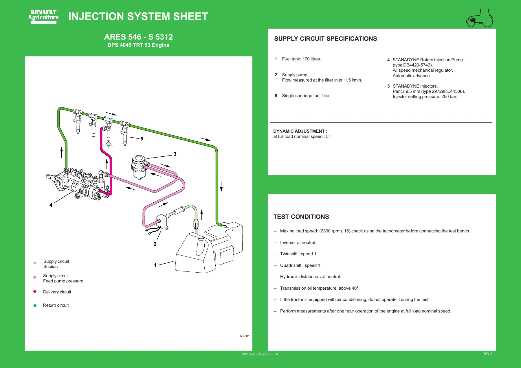
The engine section begins with dedicated injection data sheets for individual ARES tractor and engine combinations. Coverage includes DPS 4045 and 6068 engine variants used in the listed tractors, with Tier I and Tier II information. The data sheets provide fuel-system arrangements, injection-pump and injector information, test conditions and engine test data. Workshop sections then develop this into practical inspection, adjustment and repair procedures.
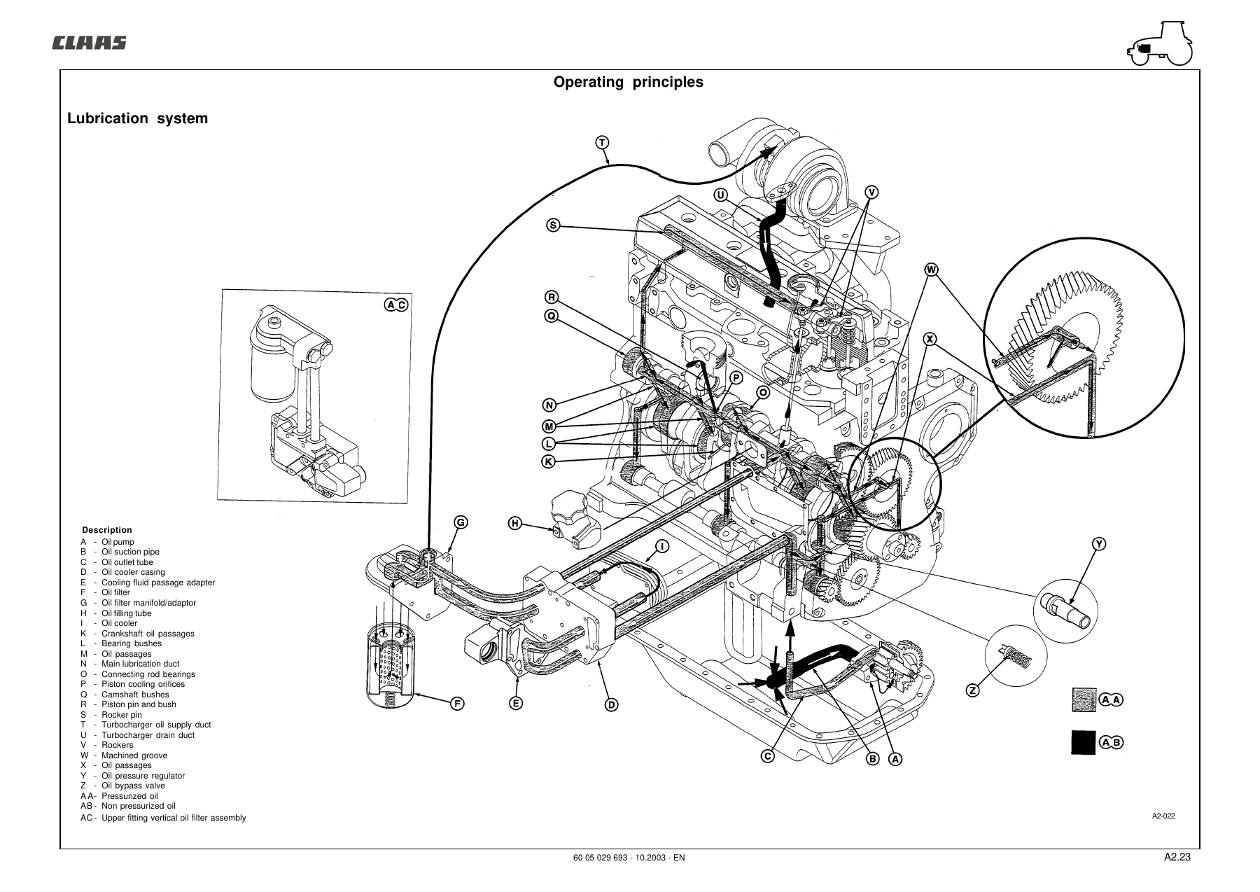
Engine service information includes identification, cylinder-head and valve specifications, cylinder block measurements, liners and pistons, connecting rods, crankshaft and bearings, flywheel, camshaft, timing components, lubrication, cooling and turbocharging. Procedures cover compression testing, engine-oil-pressure checks, valve lift and clearance, valve-adjustment sequences, supercharging-pressure checks and belt tensioner inspection. Major dismantling and rebuilding work is also covered, including separating the engine from the front axle or gearbox, cylinder-head work, liner service, piston and connecting-rod work, crankshaft and bearing service, lubrication-system repairs, cooling-system work and turbocharger procedures.
The injection chapters include fuel-filter replacement, fuel-system bleeding, injection-pump removal and installation, injector removal and installation, injector adjustment, cracking-pressure and needle-stroke adjustment, injection-pump static and dynamic setting, supply-pressure checks and accelerator-control adjustment. Diagnostic sheets address conditions including engine starting problems, irregular running, grey or black smoke, white smoke, excessive oil consumption, abnormal oil pressure and cooling-temperature faults.
Transmission, Hydraulics and Driveline Service
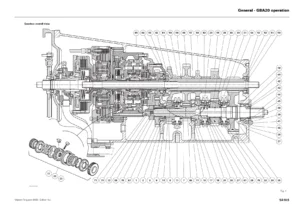
A substantial part of this CLAAS ARES workshop manual is devoted to the GBA 20 gearbox and its associated controls. It covers Revershift wet clutches, Quadrishift and Twinshift units, primary and intermediary shafts, gear controls, forks, crawler speeds, hydraulic operation and the relevant adjustments. Procedures extend beyond basic removal and replacement to clutch dismantling and reassembly, shaft timing, bearing preload, gear-control adjustment and transmission hydraulic checks.
The hydraulic material covers low-pressure gearbox and rear-axle circuits as well as the tractor’s main open-centre and closed-centre hydraulic systems. Separate chapters address open-centre hydraulics, closed-centre 110 L/min hydraulics and closed-centre 100 L/min hydraulics. Component coverage includes pumps, priority units, hydraulic covers, supply plates, lifting and auxiliary distributors, steering components and electrohydraulic equipment. Measurement and checking sections provide procedures for pressure, flow, lubrication, steering, lifting and auxiliary-distributor diagnosis.
Rear driveline coverage includes the rear axle, heavy-duty axle tubes, planetary assemblies, differential, drive pinion, bearing preload and backlash adjustments. Rear PTO information covers clutch work, upper and lower shafts, 540 and 1000 rpm arrangements, proportional PTO equipment and control adjustment. The manual also covers service brakes, hand brake, brake boosters, bleeding procedures and the 4WD power take-off housing.
Front Axle, Electrical and Electronic Systems
Both standard and Proactiv front axle sections are included. These chapters cover differential and bevel gear assemblies, epicyclic reducers, wheel hubs, steering links, universal drive shafts, axle body service, wheel alignment, final-drive settings and differential adjustments. Proactiv coverage adds suspension components, suspension cylinders and arms, torsion-bar preload, suspension position sensing, hydraulic checks, accumulator inflation, calibration, electrical checks and breakdown diagnosis.
The electricity chapter contains wiring and general lists, functional schematic diagrams, connector information and harness tracking. It is complemented by electronic-system chapters for the instrument panel, electronic/radar lift, Drivetronic III, Infotrac and ISO socket, Electropilot, Tier II Drivetronic functions and Tier II engine management. These sections provide component locations, sensor and solenoid information, electrical testing, calibration, control functions, Metadiag diagnostic procedures, transmission-related electronic tests and SPN/FMI code coverage.
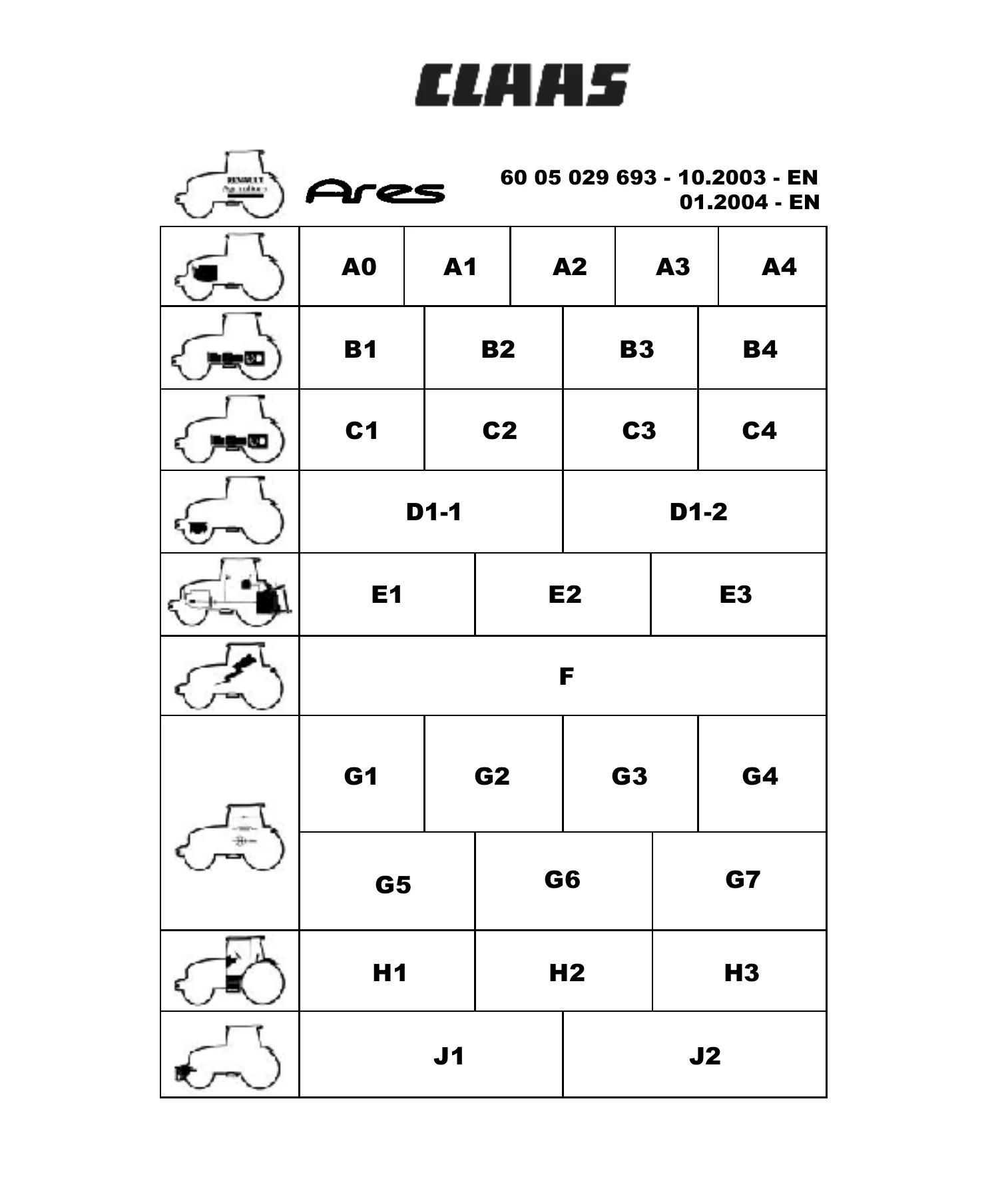
Chapters Covered
- A0 – Injection Data Sheets
- Tier I and Tier II engine and fuel-injection data
- A1 – Injection Feed Tier I
- Identification, specifications, operating principles, adjustments, removal and installation, diagnostics and injection tools
- A2 – Engine Tier I
- General and dimensional specifications, engine systems, checks, overhaul procedures, diagnostics and special tools
- A3 – Injection Additive Tier II
- Injection operation, adjustments, pump service, diagnostics and tools
- A4 – Engine Additive Tier II
- Engine specifications, torque data, checks, installation information and Tier II procedures
- B1 – GBA 20 Gearbox
- Revershift, Quadrishift, Twinshift, shafts, controls, crawler speeds, dismantling and adjustment
- B2 – Low Pressure Hydraulic Circuit
- Gearbox and rear-axle control, lubrication and hydraulic measurement points
- B3 – Gearbox Additive Tier II
- Quadrishift overdrive and rear intermediary shaft procedures
- B4 – Low Pressure Hydraulic Circuit Additive Tier II
- LS 100 L/min circuit, lubrication, control-pressure and flow checks
- C1 – Rear Axle
- Axle tubes, differential, drive pinion, rear PTO and adjustment procedures
- C2 – Service Brakes and Hand Brake
- Master cylinders, boosters, pedal adjustment, bleeding and hand-brake service
- C3 – 4WD Power Take-Off Housing
- Clutch removal, dismantling, reassembly and installation
- C4 – Rear Axle Additive Tier II
- Heavy-duty axle information and proportional PTO
- D1-1 – Standard Front Axle
- Differential, hubs, steering, final-drive adjustments and hydraulic/electrical checks
- D1-2 – Proactiv Front Axle
- Suspension, differential, wheel hubs, hydraulic tests, calibration and diagnosis
- E1 – Open Centre Hydraulics
- Pump, distributors, lift, steering, checking points and steering diagnosis
- E2 – Closed Centre Hydraulics 110 L/min
- Variable-capacity pump, priority units, distributors and pressure/flow checks
- E3 – Closed Centre Hydraulics 100 L/min
- Main and steering pumps, hydraulic covers, pressure, flow and braking-valve checks
- F – Electricity
- Wiring lists, functional schematics, connectors and harness tracking
- G1 – Instrument Panel
- Indicators, sensors, calibration and Metadiag diagnosis
- G2 – Electronic/Radar Lift
- TCE lift systems, sensors, connections and diagnostic procedures
- G3 – Drivetronic III
- Transmission controls, sensors, calibration, electronic functions, error codes and electrical tests
- G4 – Infotrac and ISO Socket
- On-board computer, ISO connections, electrical checks and calibration
- G5 – Electropilot
- Joystick, electrohydraulic distributor, electrical checks and Metadiag diagnosis
- G6 – Drivetronic III Tier II Additive
- Tier II sensors, range change, clutch calibration and electrical tests
- G7 – Engine Management Tier II
- Components, sensors, accelerator adjustment, diagnostics and SPN/FMI codes
- J1 – Lift and Front Power Take-Off
- Front lift, front PTO, exploded views, clutch work and pressure checks
- J2 – Pneumatic Braking
- Operating principles, compressor, regulator, reservoir, trailer controls and bleeding
Taken together, these chapters give technicians a single reference for mechanical overhaul, hydraulic troubleshooting, electrical diagnosis and system adjustment across the covered CLAAS ARES tractors. The combination of specifications, illustrated procedures, circuit information and diagnostic material makes the manual useful for both fault-finding and major component repair.
Workshop Procedures, Specifications and Diagnostic Information
The CLAAS ARES 546 556 566 616 626 636 696 Workshop Service Repair Manual PDF is particularly detailed where accurate measurement and adjustment matter. The engine chapters include dimensional limits for internal parts, compression and pressure checks, valve and timing data, tightening information and dedicated repair procedures. Transmission and axle chapters provide preload, backlash, timing and control adjustments, while hydraulic chapters identify measurement points and test procedures for pressure and flow. The electrical and electronic sections add wiring diagrams, connector identification, sensor checks, calibration routines and diagnostic-code information.
Illustrated special-tool sections are included throughout the manual for injection, engine, gearbox, axle, hydraulic, electrical and electronic work. Exploded views and component cross-sections help identify assemblies before dismantling, while operating diagrams explain how fuel, lubrication, cooling, hydraulic and electronic-control systems function before troubleshooting begins.
Repair Your CLAAS ARES with the Correct Workshop Information
Whether the job involves engine diagnosis, injection-system adjustment, gearbox overhaul, hydraulic pressure testing, axle repair, brake service, PTO work, wiring faults or electronic-system calibration, this CLAAS ARES 546 556 566 616 626 636 696 Workshop Service Repair Manual PDF provides the procedures and technical reference needed to approach the work systematically. Having the correct sequences, measurements, torque information, diagrams and diagnostic checks available can help avoid incorrect adjustment and unnecessary component replacement.
Delivered as an instant PDF download with no shipping required. The manual can be opened on compatible phones, tablets and computers and printed when a paper workshop copy or selected service pages are needed.
Reviews
There are no reviews yet.