★ TRUSTED BY 321,897+ PROFESSIONALS WORLDWIDE
🏒
Trusted Business
Verified & Licensed
πŸ›‘οΈ
Virus Free Files
100% Safe Downloads
πŸ”’
Secure Payment
SSL Protected
⚑
Instant Delivery
Available Immediately
Sale!

CRJ200 Aircraft Maintenance Manual – Pneumatic System Chapter 36 PDF Download

Original price was: $34.95.Current price is: $21.95.

Complete Chapter 36 Pneumatic System maintenance manual for the Canadair CRJ200 regional jet. Covers 10th and 14th stage bleed air distribution, leak detection, control valves, ducting, pressure indicating, and all associated removal, installation, testing, and inspection procedures.

⚑
Instant PDF Download
Available immediately
πŸ’Ύ
Save to Your Device
Download & keep forever
πŸ›‘οΈ
Antivirus Scanned
100% virus-free
🌍
Trusted Worldwide
175,000+ customers

Description

CRJ200 Pneumatic System Maintenance Manual – Chapter 36

This is the complete Chapter 36 Pneumatic section of the Canadair Regional Jet CRJ200 Aircraft Maintenance Manual. It contains the full description, operation, removal, installation, adjustment, test, inspection, and troubleshooting procedures for the aircraft pneumatic system, covering both the 10th-stage and 14th-stage bleed air systems. The manual is written for aircraft maintenance engineers and technicians working on the CRJ200 platform and provides the detailed procedural guidance needed for line and base maintenance tasks.

File Details

  • Manual Type: Aircraft Maintenance Manual (AMM) – Chapter 36 Pneumatic
  • Brand: Canadair Regional Jet (Bombardier)
  • Model: CRJ200
  • Language: English
  • Page Count: 394 pages
  • File Format: PDF
  • Document Dates: Apr 20/2004 through Dec 10/2005 revisions

Chapters Covered

  • 36-10-00 – Pneumatic: General, Description and Operation, Distribution System, Indicating System
  • 36-11-00 – Bleed Air Distribution: General, Description, 10th-Stage Bleed-Air System, 14th-Stage Bleed-Air System, Operation
  • 36-11-01 – Check Valve, Manifold: Removal/Installation of the Bleed Air Check Valve
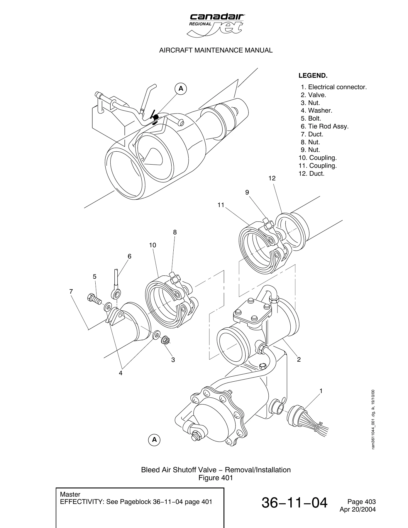
  • 36-11-04 – Valve, Bleed Air Shutoff: Removal/Installation of the Bleed Air Shutoff Valve
  • 36-11-07 – Valve, Isolation: Removal/Installation of the Isolation Valve
  • 36-11-10 – Check Valve, APU Supply: Removal/Installation, Inspection/Check of the APU-Supply Check Valve
  • 36-11-27 – Check Valve, Ground-Connect: Removal/Installation of the Ground-Connect 10th-Stage Bleed Air Check Valve
  • 36-11-31 – Ducting, 10th Stage Bleed-Air: Removal/Installation of Left and Right Engine Ducting, General Visual Inspection
  • 36-11-35 – Ducting, Fuselage 10th Stage Bleed-Air: Removal/Installation of Fuselage Ducting
  • 36-12-00 – 14th-Stage Bleed Air System: Description and Operation, Component Details, Operation, Deactivation/Reactivation of the 14th-Stage Bleed Air Shutoff Valve, Leak Test of the 14th-Stage Bleed Air Ducts
  • 36-12-01 – Valve, Bleed-Air Shutoff: Removal/Installation of the Bleed-Air Shutoff Valve
  • 36-12-04 – 14th Stage Bleed-Air Ducting: Removal/Installation of Left and Right Engine Ducting, General Visual Inspection
  • 36-20-00 – Bleed Air Indicating: General, Description, Bleed-Air Leak Detection and Warning System, 10th-Stage Bleed-Air-Manifold Indicating System
  • 36-21-00 – Bleed-Air Leak Detection and Warning System: Component Details, BLEED AIR Control Panel, Sensor Elements, Thermal Switch, Bleed-Air Leak Control-Unit, Operation, Circuit Test, Maintenance Practices
  • 36-21-01 – Panel, Bleed Air Control: Removal/Installation of the Bleed Air Control Panel
  • 36-21-04 – Element, Sensing: Removal/Installation of sensing elements for 10th-stage manifolds, fuselage, and pylon ducts
  • 36-21-07 – Switch, Thermal: Removal/Installation of leading-edge thermal switches, Adjustment/Test – Wing Leading-Edge Thermal-Switches Operational Test
  • 36-21-10 – Unit, Bleed Air Leak Control: Removal/Installation, Operational Test of the Bleed-Air Leak-Control Unit
  • 36-22-00 – Indicating, 10th-Stage Bleed Air Manifold: Description and Operation, Pressure Transducers, Component Location Index
  • 36-22-01 – Transducer, Pressure: Removal/Installation, Operational Test of the 10th-Stage Pressure Transducer

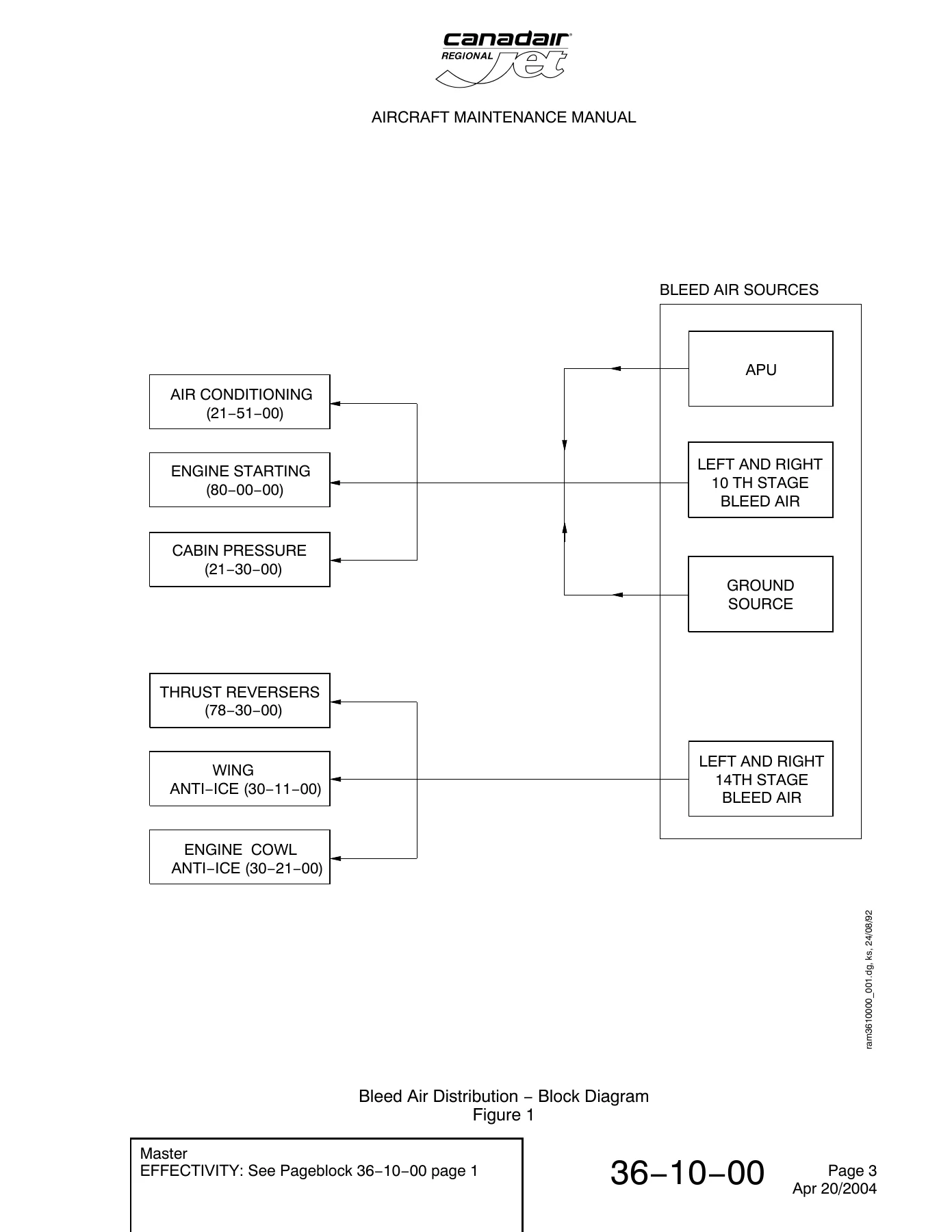
The CRJ200 pneumatic system maintenance manual provides comprehensive coverage of the aircraft bleed air architecture. It details the 10th-stage system that supplies air conditioning, cabin pressurization, and engine starting, along with the 14th-stage system that feeds the thrust reversers, wing anti-ice, and engine cowl anti-ice. The manual includes complete component descriptions for the bleed-air check valves, shutoff valves, isolation valve, APU supply check valve, and high-pressure ground-air-supply check valve. Every removal and installation procedure is documented with torque values, clearances, and safety precautions. Leak test procedures are provided for both ground air supply and engine run scenarios, with step-by-step instructions for correcting leaks at duct couplings. The bleed-air leak detection and warning system section covers the BLEED AIR control panel, sensor elements, thermal switches, and control units, including operational tests and circuit tests. The pressure indicating system section covers the pressure transducers used to monitor the 10th-stage manifold. This manual is essential for any technician performing maintenance, troubleshooting, or inspection on the CRJ200 pneumatic system.

Complete PDF Bookmark Tree

Complete Bookmarks

The complete bookmarks in the β€œCRJ200 Aircraft Maintenance Manual – Pneumatic System Chapter 36 PDF Download” are as follows:

Chapter 36
Effective Pagesp. 1
Contentsp. 7
Section 00p. 19
36-00-00p. 19
1: PNEUMATIC – DESCRIPTION AND OPERATIONp. 19
1. Generalp. 19
2. Descriptionp. 19
A. Distribution Systemp. 19
B. Indicating Systemp. 19
Section 10p. 21
36-10-00p. 21
1: BLEED AIR DISTRIBUTION – DESCRIPTION AND OPERATIONp. 21
1. Generalp. 21
2. Descriptionp. 21
A. 10th-Stage Bleed-Air Systemp. 21
B. 14th-Stage Bleed-Air Systemp. 21
3. Operationp. 21
A. 10th-Stage Bleed-Air Systemp. 21
B. 14th-Stage Bleed-Air Systemp. 21
Bleed Air Distribution – Block Diagramp. 23
Figure 1p. 23
Section 11p. 25
36-11-00p. 25
1: 10TH-STAGE BLEED AIR SYSTEM – DESCRIPTION AND OPERATIONp. 25
1. Generalp. 25
2. Component Detailsp. 25
A. Bleed-Air Check Valvep. 25
B. Bleed-Air Shutoff Valvesp. 25
C. Isolation Valvep. 25
D. APU Supply Check-Valvep. 25
E. High-Pressure Ground-Air-Supply Check-Valvep. 25
F. Ductsp. 26
3. Operationp. 26
4. Component Location Indexp. 26
10th-Stage Bleed Air System – Component Location/Recognitionp. 28
Figure 1 (Sheet 1 of 2)p. 28
Figure 1 (Sheet 2 of 2)p. 29
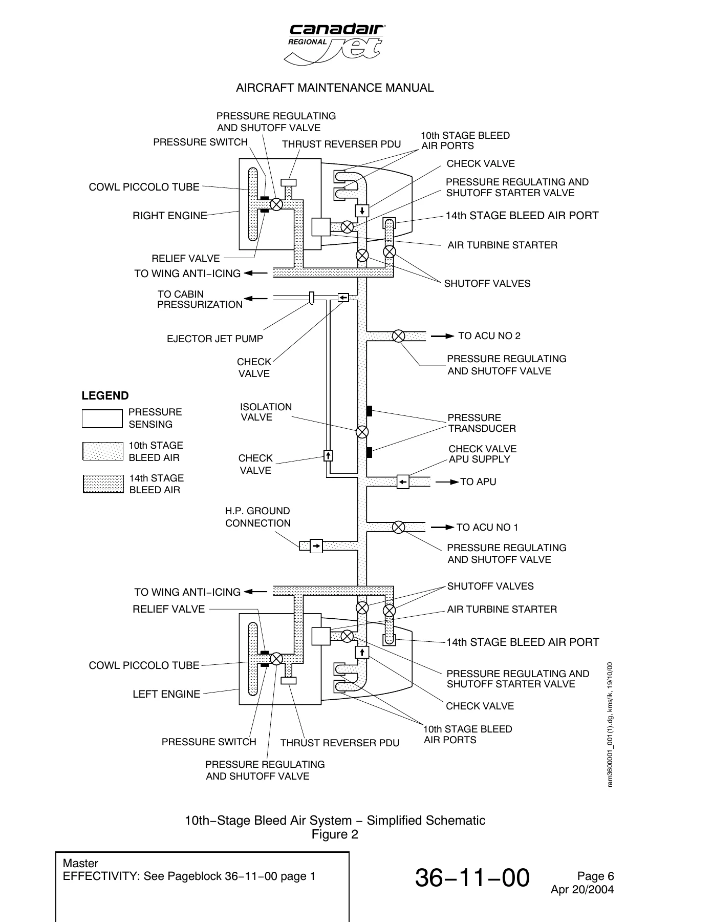
10th-Stage Bleed Air System – Simplified Schematicp. 30
Figure 2p. 30
10th-Stage Bleed Air System – Component Accessp. 31
Figure 3p. 31
501: 10TH-STAGE BLEED-AIR SYSTEM (FUSELAGE) – ADJUSTMENT/TESTp. 33
1. Generalp. 33
Task 36-11-00-790-801 Leak Test of the 10th-Stage Bleed-Air System (Ground Air Supply)p. 33
1. Job Set-Up Informationp. 33
Subtask 36-11-00-943-001p. 33
Subtask 36-11-00-944-001p. 33
Subtask 36-11-00-946-001p. 33
2. Job Set-Upp. 33
Subtask 36-11-00-865-001p. 33
Subtask 36-11-00-865-002p. 34
Subtask 36-11-00-865-004p. 34
Subtask 36-11-00-010-001p. 34
Subtask 36-11-00-490-001p. 34
Subtask 36-11-00-861-001p. 34
3. Procedurep. 35
Subtask 36-11-00-840-001p. 35
Subtask 36-11-00-880-001p. 35
Subtask 36-11-00-790-001p. 35
Subtask 36-11-00-790-002p. 35
Subtask 36-11-00-790-003p. 36
4. Close Outp. 36
Subtask 36-11-00-090-001p. 36
Subtask 36-11-00-861-002p. 36
Subtask 36-11-00-865-003p. 36
Subtask 36-11-00-865-005p. 37
Subtask 36-11-00-941-001p. 37
Subtask 36-11-00-410-001p. 37
Task 36-11-00-790-802 Leak Test of the 10th-Stage Bleed-Air System (Engine Run)p. 38
1. Job Set-Up Informationp. 38
Subtask 36-11-00-944-002p. 38
Subtask 36-11-00-946-002p. 38
2. Job Set-Upp. 38
Subtask 36-11-00-010-002p. 38
Subtask 36-11-00-869-001p. 38
Subtask 36-11-00-868-001p. 38
Subtask 36-11-00-868-002p. 38
Subtask 36-11-00-868-003p. 38
3. Procedurep. 39
Subtask 36-11-00-790-004p. 39
Subtask 36-11-00-790-005p. 39
Subtask 36-11-00-790-006p. 40
4. Close Outp. 40
Subtask 36-11-00-868-004p. 40
Subtask 36-11-00-869-002p. 40
Subtask 36-11-00-941-002p. 40
Subtask 36-11-00-410-002p. 40
36-11-01p. 41
401: BLEED AIR CHECK VALVE – REMOVAL/INSTALLATIONp. 41
1. Generalp. 41
Task 36-11-01-000-801 Removal of the Bleed Air Check Valvep. 41
1. Job Set-Up Informationp. 41
Subtask 36-11-01-946-001p. 41
2. Job Set-Upp. 41
Subtask 36-11-01-865-001p. 41
Subtask 36-11-01-865-003p. 42
Subtask 36-11-01-943-001p. 42
Subtask 36-11-01-010-001p. 42
Subtask 36-11-01-010-002p. 42
3. Procedurep. 42
Subtask 36-11-01-030-001p. 42
Bleed Air Check Valve – Removal/Installationp. 44
Figure 401p. 44
Task 36-11-01-400-801 Installation of the Bleed Air Check Valvep. 45
1. Job Set-Up Informationp. 45
Subtask 36-11-01-946-002p. 45
2. Procedurep. 45
Subtask 36-11-01-869-001p. 45
Subtask 36-11-01-430-001p. 45
3. Close Outp. 46
Subtask 36-11-01-865-002p. 46
Subtask 36-11-01-865-004p. 46
Subtask 36-11-01-790-001p. 46
Subtask 36-11-01-410-001p. 46
Subtask 36-11-01-410-002p. 46
Subtask 36-11-01-941-001p. 47
36-11-04p. 49
401: VALVE, BLEED AIR SHUTOFF – REMOVAL/INSTALLATIONp. 49
1. Generalp. 49
Task 36-11-04-000-801 Removal of the Bleed Air Shutoff Valvep. 49
1. Job Set-Upp. 49
Subtask 36-11-04-865-001p. 49
Subtask 36-11-04-865-003p. 49
Subtask 36-11-04-010-001p. 50
2. Procedurep. 50
Subtask 36-11-04-030-001p. 50
Bleed Air Shutoff Valve – Removal/Installationp. 51
Figure 401p. 51
Task 36-11-04-400-801 Installation of the Bleed Air Shutoff Valvep. 52
1. Job Set-Up Informationp. 52
Subtask 36-11-04-945-001p. 52
Subtask 36-11-04-946-001p. 52
2. Procedurep. 52
Subtask 36-11-04-869-001p. 52
Subtask 36-11-04-430-001p. 52
Subtask 36-11-04-430-002p. 52
Subtask 36-11-04-430-003p. 52
3. Close Outp. 53
Subtask 36-11-04-865-002p. 53
Subtask 36-11-04-865-004p. 53
Subtask 36-11-04-790-001p. 54
Subtask 36-11-04-410-001p. 54
Subtask 36-11-04-941-001p. 54
36-11-07p. 55
401: VALVE, ISOLATION – REMOVAL/INSTALLATIONp. 55
1. Generalp. 55
Task 36-11-07-000-801 Removal of the Isolation Valvep. 55
1. Job Set-Upp. 55
Subtask 36-11-07-865-001p. 55
Subtask 36-11-07-865-003p. 55
Subtask 36-11-07-010-001p. 55
2. Procedurep. 56
Subtask 36-11-07-020-001p. 56
Isolation Valve – Removal/Installationp. 57
Figure 401p. 57
Task 36-11-07-400-801 Installation of the Isolation Valvep. 58
1. Job Set-Up Informationp. 58
Subtask 36-11-07-945-001p. 58
Subtask 36-11-07-946-001p. 58
2. Procedurep. 58
Subtask 36-11-07-869-001p. 58
Subtask 36-11-07-430-001p. 58
Subtask 36-11-07-420-001p. 58
3. Close Outp. 59
Subtask 36-11-07-865-002p. 59
Subtask 36-11-07-865-004p. 59
Subtask 36-11-07-790-001p. 59
Subtask 36-11-07-410-001p. 60
Subtask 36-11-07-941-001p. 60
36-11-10p. 61
401: CHECK VALVE, AUXILIARY POWER UNIT (APU) SUPPLY – REMOVAL/INSTALLATIONp. 61
1. Generalp. 61
Task 36-11-10-000-801 Removal of the APU-Supply Check Valvep. 61
1. Job Set-Upp. 61
Subtask 36-11-10-865-001p. 61
Subtask 36-11-10-010-001p. 61
Subtask 36-11-10-941-001p. 61
2. Procedurep. 61
Subtask 36-11-10-020-001p. 61
APU Supply Check Valve – Removal/Installationp. 63
Figure 401p. 63
Task 36-11-10-400-801 Installation of the APU-Supply Check Valvep. 64
1. Job Set-Up Informationp. 64
Subtask 36-11-10-945-001p. 64
Subtask 36-11-10-946-001p. 64
2. Procedurep. 64
Subtask 36-11-10-869-001p. 64
Subtask 36-11-10-420-001p. 64
3. Close Outp. 65
Subtask 36-11-10-941-002p. 65
Subtask 36-11-10-865-002p. 65
Subtask 36-11-10-790-001p. 65
Subtask 36-11-10-410-001p. 65
Subtask 36-11-10-943-001p. 65
601: CHECK VALVE, AUXILIARY POWER UNIT (APU) SUPPLY – INSPECTION/CHECKp. 67
1. Generalp. 67
Task 36-11-10-210-801 Detailed Inspection of the APU-Supply Check Valvep. 67
1. Reason for the Jobp. 67
2. Job Set-Up Informationp. 67
Subtask 36-11-10-946-002p. 67
3. Job Set-Upp. 67
Subtask 36-11-10-020-002p. 67
4. Procedurep. 67
Subtask 36-11-10-210-001p. 67
5. Close Outp. 67
Subtask 36-11-10-420-002p. 67
Subtask 36-11-10-941-003p. 67
36-11-27p. 69
401: CHECK VALVE, GROUND-CONNECT 10TH-STAGE BLEED AIR SYSTEM – REMOVAL/INSTALLATIONp. 69
1. Generalp. 69
Task 36-11-27-000-801 Removal of the Ground-Connect 10th-stage Bleed Air Check Valvep. 69
1. Job Set-Upp. 69
Subtask 36-11-27-865-001p. 69
Subtask 36-11-27-010-001p. 69
2. Procedurep. 69
Subtask 36-11-27-020-002p. 69
Subtask 36-11-27-020-001p. 70
Ground-Connect Check Valve – Removal/Installationp. 71
Figure 401p. 71
Ground-Connect Check Valve – Removal/Installation (1)p. 72
Figure 402p. 72
Task 36-11-27-400-801 Installation of the Ground-Connect Check Valvep. 73
1. Job Set-Up Informationp. 73
Subtask 36-11-27-944-001p. 73
Subtask 36-11-27-945-001p. 73
Subtask 36-11-27-945-002p. 73
Subtask 36-11-27-946-001p. 73
2. Procedurep. 74
Subtask 36-11-27-420-001p. 74
Subtask 36-11-27-420-002p. 74
3. Close Outp. 75
Subtask 36-11-27-865-002p. 75
Subtask 36-11-27-790-001p. 75
Subtask 36-11-27-941-001p. 75
Subtask 36-11-27-410-001p. 75
36-11-31p. 77
401: DUCTING, 10TH STAGE BLEED-AIR – REMOVAL/INSTALLATIONp. 77
1. Generalp. 77
Task 36-11-31-000-801 Removal of the Left Engine 10th Stage Bleed-Air Ductingp. 77
1. Job Set-Up Informationp. 77
Subtask 36-11-31-946-001p. 77
2. Job Set-Upp. 77
Subtask 36-11-31-865-001p. 77
Subtask 36-11-31-865-005p. 77
Subtask 36-11-31-010-002p. 78
3. Procedurep. 78
Subtask 36-11-31-020-001p. 78
Subtask 36-11-31-020-002p. 78
Subtask 36-11-31-030-001p. 79
Left Engine 10th Stage Bleed-Air Ducting – Removal/Installationp. 80
Figure 401 (Sheet 1 of 2)p. 80
Figure 401 (Sheet 2 of 2)p. 81
Task 36-11-31-400-801 Installation of the Left Engine 10th Stage Bleed-Air Ductingp. 82
1. Job Set-Up Informationp. 82
Subtask 36-11-31-943-001p. 82
Subtask 36-11-31-944-001p. 82
Subtask 36-11-31-945-001p. 82
Subtask 36-11-31-946-002p. 83
2. Job Set-Upp. 83
Subtask 36-11-31-869-001p. 83
3. Procedurep. 83
Subtask 36-11-31-430-001p. 83
Subtask 36-11-31-420-001p. 84
Subtask 36-11-31-420-002p. 84
Subtask 36-11-31-820-001p. 85
4. Close Outp. 87
Subtask 36-11-31-865-002p. 87
Subtask 36-11-31-865-006p. 87
Subtask 36-11-31-790-001p. 87
Subtask 36-11-31-941-002p. 88
Subtask 36-11-31-410-002p. 88
Task 36-11-31-000-802 Removal of the Right Engine 10th Stage Bleed-Air Ductingp. 89
1. Job Set-Up Informationp. 89
Subtask 36-11-31-946-003p. 89
2. Job Set-Upp. 89
Subtask 36-11-31-865-003p. 89
Subtask 36-11-31-865-007p. 89
Subtask 36-11-31-010-003p. 89
3. Procedurep. 90
Subtask 36-11-31-020-003p. 90
Subtask 36-11-31-020-004p. 90
Subtask 36-11-31-030-002p. 91
Right Engine 10th Stage Bleed-Air Ducting – Removal/Installationp. 92
Figure 402 (Sheet 1 of 2)p. 92
Figure 402 (Sheet 2 of 2)p. 93
Task 36-11-31-400-802 Installation of the Right Engine 10th Stage Bleed-Air Ductingp. 94
1. Job Set-Up Informationp. 94
Subtask 36-11-31-943-002p. 94
Subtask 36-11-31-945-002p. 94
Subtask 36-11-31-946-004p. 95
2. Job Set-Upp. 95
Subtask 36-11-31-869-002p. 95
3. Procedurep. 95
Subtask 36-11-31-430-002p. 95
Subtask 36-11-31-420-003p. 96
Subtask 36-11-31-420-004p. 96
4. Close Outp. 97
Subtask 36-11-31-865-004p. 97
Subtask 36-11-31-865-008p. 98
Subtask 36-11-31-790-002p. 98
Subtask 36-11-31-941-003p. 98
Subtask 36-11-31-210-002p. 98
Subtask 36-11-31-410-003p. 98
601: DUCTING, 10TH STAGE BLEED-AIR – INSPECTION/CHECKp. 99
1. Generalp. 99
Task 36-11-31-210-801 General Visual Inspection of the 10th Stage Bleed-Air Ductingp. 99
1. Job Set-Upp. 99
Subtask 36-11-31-010-001p. 99
2. Procedurep. 99
Subtask 36-11-31-210-001p. 99
3. Close Outp. 99
Subtask 36-11-31-941-001p. 99
Subtask 36-11-31-410-001p. 99
36-11-35p. 101
401: DUCTING, FUSELAGE 10TH STAGE BLEED-AIR – REMOVAL/INSTALLATIONp. 101
1. Generalp. 101
Task 36-11-35-000-802 Removal of the Fuselage 10th Stage Bleed-Air Ductingp. 101
1. Job Set-Up Informationp. 101
Subtask 36-11-35-943-003p. 101
2. Job Set-Upp. 101
Subtask 36-11-35-941-004p. 101
Subtask 36-11-35-865-003p. 101
Subtask 36-11-35-865-005p. 102
Subtask 36-11-35-010-002p. 102
Subtask 36-11-35-490-002p. 102
3. Procedurep. 102
Subtask 36-11-35-020-020p. 103
Subtask 36-11-35-020-021p. 103
Subtask 36-11-35-020-022p. 104
Subtask 36-11-35-020-023p. 104
Subtask 36-11-35-020-024p. 104
Subtask 36-11-35-020-025p. 105
Subtask 36-11-35-020-026p. 105
Subtask 36-11-35-020-027p. 106
Subtask 36-11-35-020-028p. 106
Subtask 36-11-35-020-029p. 106
Subtask 36-11-35-020-030p. 107
Subtask 36-11-35-020-031p. 107
Subtask 36-11-35-020-032p. 107
Subtask 36-11-35-020-033p. 108
Subtask 36-11-35-020-034p. 108
10th Stage Bleed-air Fuselage Ducting – Removal/Installationp. 110
Figure 401 (Sheet 1 of 7)p. 110
Figure 401 (Sheet 2 of 7)p. 111
Figure 401 (Sheet 3 of 7)p. 112
Figure 401 (Sheet 4 of 7)p. 113
Figure 401 (Sheet 5 of 7)p. 114
Figure 401 (Sheet 6 of 7)p. 115
Figure 401 (Sheet 7 of 7)p. 116
Task 36-11-35-420-802 Installation of the Fuselage 10th Stage Bleed-Air Ductingp. 117
1. Job Set-Up Informationp. 117
Subtask 36-11-35-943-004p. 117
Subtask 36-11-35-944-003p. 117
Subtask 36-11-35-944-004p. 117
Subtask 36-11-35-946-003p. 118
2. Job Set-Upp. 118
Subtask 36-11-35-869-002p. 118
3. Procedurep. 119
Subtask 36-11-35-420-016p. 119
Subtask 36-11-35-420-017p. 119
Subtask 36-11-35-420-018p. 119
Subtask 36-11-35-420-019p. 120
Subtask 36-11-35-420-020p. 120
Subtask 36-11-35-420-021p. 121
Subtask 36-11-35-420-022p. 121
Subtask 36-11-35-420-023p. 122
Subtask 36-11-35-420-024p. 123
Subtask 36-11-35-420-025p. 123
Subtask 36-11-35-420-026p. 124
Subtask 36-11-35-420-027p. 124
Subtask 36-11-35-430-006p. 124
Subtask 36-11-35-420-028p. 125
Subtask 36-11-35-420-029p. 125
Subtask 36-11-35-420-030p. 126
Subtask 36-11-35-430-007p. 126
4. Close Outp. 127
Subtask 36-11-35-865-004p. 127
Subtask 36-11-35-865-006p. 127
Subtask 36-11-35-941-005p. 128
Subtask 36-11-35-790-002p. 128
Subtask 36-11-35-941-006p. 128
Subtask 36-11-35-410-002p. 128
Section 12p. 129
36-12-00p. 129
1: 14TH-STAGE BLEED-AIR SYSTEM – DESCRIPTION AND OPERATIONp. 129
1. Generalp. 129
2. Component Detailsp. 129
A. Bleed-Air Shutoff Valvesp. 129
B. Check Valvep. 129
C. Ductsp. 129
3. Operationp. 129
4. Component Location Indexp. 129
14th-Stage Bleed-Air System – Component Location/Recognitionp. 131
Figure 1p. 131
14th-Stage Bleed-Air System – Schematicp. 132
Figure 2p. 132
14th-Stage Bleed-Air System – Component Accessp. 133
Figure 3p. 133
401: 14TH-STAGE BLEED AIR SYSTEM – REMOVAL/INSTALLATIONp. 135
1. Generalp. 135
Task 36-12-00-040-801 Deactivation of the 14th-Stage Bleed Air Shutoff Valvep. 135
1. Reason for the Jobp. 135
2. Job Set-Up Informationp. 135
Subtask 36-12-00-946-004p. 135
Subtask 36-12-00-943-002p. 135
Subtask 36-12-00-944-002p. 135
3. Job Set-Upp. 135
Subtask 36-12-00-865-003p. 135
Subtask 36-12-00-010-004p. 136
4. Procedurep. 136
Subtask 36-12-00-040-005p. 136
5. Close Outp. 137
Subtask 36-12-00-941-004p. 137
Subtask 36-12-00-010-005p. 137
Subtask 36-12-00-040-006p. 137
Deactivation/Reactivation of the 14th-Stage Bleed-Air Shutoff-Valvep. 138
Figure 401p. 138
Task 36-12-00-040-802 Reactivation of the 14th-Stage Bleed-Air Shutoff-Valvep. 139
1. Reason for the Jobp. 139
2. Job Set-Up Information (1)p. 139
Subtask 36-12-00-946-002p. 139
Subtask 36-12-00-944-003p. 139
3. Job Set-Up (1)p. 139
Subtask 36-12-00-010-006p. 139
4. Procedure (1)p. 139
Subtask 36-12-00-440-001p. 139
5. Close Out (1)p. 141
Subtask 36-12-00-941-002p. 141
Subtask 36-12-00-410-004p. 141
Subtask 36-12-00-440-002p. 141
501: 14TH-STAGE BLEED AIR SYSTEM – ADJUSTMENT/TESTp. 143
1. Generalp. 143
Task 36-12-00-790-801 Leak Test of the 14th-Stage Bleed Air Ductsp. 143
1. Job Set-Up Informationp. 143
Subtask 36-12-00-943-001p. 143
Subtask 36-12-00-944-001p. 143
Subtask 36-12-00-946-003p. 143
2. Job Set-Upp. 144
Subtask 36-12-00-865-007p. 144
Subtask 36-12-00-010-001p. 144
Subtask 36-12-00-010-002p. 144
Subtask 36-12-00-010-003p. 145
Subtask 36-12-00-861-006p. 145
3. Procedurep. 145
Subtask 36-12-00-840-001p. 145
Subtask 36-12-00-030-001p. 145
Subtask 36-12-00-790-001p. 145
Subtask 36-12-00-790-002p. 146
Subtask 36-12-00-863-001p. 147
Subtask 36-12-00-080-001p. 147
Subtask 36-12-00-430-001p. 147
4. Close Outp. 147
Subtask 36-12-00-861-005p. 147
Subtask 36-12-00-865-008p. 147
Subtask 36-12-00-865-004p. 148
Subtask 36-12-00-410-001p. 148
Subtask 36-12-00-410-002p. 148
Subtask 36-12-00-410-003p. 148
Subtask 36-12-00-941-003p. 149
36-12-01p. 151
401: BLEED-AIR SHUTOFF VALVE – REMOVAL/INSTALLATIONp. 151
1. Generalp. 151
Task 36-12-01-000-801 Removal of the Bleed-Air Shutoff Valvep. 151
1. Job Set-Upp. 151
Subtask 36-12-01-865-001p. 151
Subtask 36-12-01-865-003p. 151
Subtask 36-12-01-010-001p. 152
2. Procedurep. 152
Subtask 36-12-01-020-001p. 152
Bleed Air Shutoff Valve – Removal/Installationp. 153
Figure 401p. 153
Task 36-12-01-400-801 Installation of the Bleed-Air Shutoff Valvep. 154
1. Job Set-Up Informationp. 154
Subtask 36-12-01-944-001p. 154
Subtask 36-12-01-945-001p. 154
Subtask 36-12-01-946-001p. 154
2. Procedurep. 154
Subtask 36-12-01-869-001p. 154
Subtask 36-12-01-430-001p. 154
Subtask 36-12-01-420-001p. 155
3. Close Outp. 155
Subtask 36-12-01-865-002p. 155
Subtask 36-12-01-865-004p. 156
Subtask 36-12-01-790-001p. 156
Subtask 36-12-01-430-004p. 156
Subtask 36-12-01-410-001p. 156
Subtask 36-12-01-941-001p. 156
36-12-04p. 157
401: DUCTING, 14TH-STAGE BLEED-AIR – REMOVAL/INSTALLATIONp. 157
1. Generalp. 157
Task 36-12-04-000-801 Removal of the Left Engine 14th-Stage Bleed-Air Ductingp. 157
1. Job Set-Up Informationp. 157
Subtask 36-12-04-946-001p. 157
2. Job Set-Upp. 157
Subtask 36-12-04-865-001p. 157
Subtask 36-12-04-865-005p. 157
Subtask 36-12-04-010-002p. 158
3. Procedurep. 158
Subtask 36-12-04-020-001p. 158
Subtask 36-12-04-030-001p. 158
Left Engine 14th Stage Bleed-Air Ducting – Removal/Installationp. 160
Figure 401 (Sheet 1 of 2)p. 160
Figure 401 (Sheet 2 of 2)p. 161
Task 36-12-04-400-801 Installation of the Left Engine 14th-Stage Bleed-Air Ductingp. 162
1. Job Set-Up Informationp. 162
Subtask 36-12-04-943-001p. 162
Subtask 36-12-04-944-001p. 162
Subtask 36-12-04-945-001p. 162
Subtask 36-12-04-946-002p. 163
2. Job Set-Upp. 163
Subtask 36-12-04-869-001p. 163
3. Procedurep. 163
Subtask 36-12-04-430-001p. 163
Subtask 36-12-04-420-001p. 164
4. Close Outp. 165
Subtask 36-12-04-865-002p. 165
Subtask 36-12-04-865-006p. 165
Subtask 36-12-04-790-001p. 165
Subtask 36-12-04-941-002p. 165
Subtask 36-12-04-410-002p. 166
Task 36-12-04-000-808 Removal of the Right Engine 14th-STAGE Bleed-Air Ductingp. 167
1. Job Set-Up Informationp. 167
Subtask 36-12-04-946-013p. 167
2. Job Set-Upp. 167
Subtask 36-12-04-865-024p. 167
Subtask 36-12-04-865-025p. 167
Subtask 36-12-04-010-009p. 167
3. Procedurep. 168
Subtask 36-12-04-020-008p. 168
Right Engine 14th Stage Bleed-Air Ducting – Removal/Installationp. 169
Figure 402p. 169
Task 36-12-04-400-802 Installation of the Right Engine 14th-Stage Bleed-Air Ductingp. 170
1. Job Set-Up Informationp. 170
Subtask 36-12-04-943-002p. 170
Subtask 36-12-04-944-002p. 170
Subtask 36-12-04-945-002p. 170
Subtask 36-12-04-946-004p. 170
2. Job Set-Upp. 171
Subtask 36-12-04-869-002p. 171
3. Procedurep. 171
Subtask 36-12-04-420-002p. 171
4. Close Outp. 172
Subtask 36-12-04-865-004p. 172
Subtask 36-12-04-865-008p. 172
Subtask 36-12-04-790-002p. 172
Subtask 36-12-04-941-003p. 172
Subtask 36-12-04-410-003p. 172
601: 14TH STAGE BLEED-AIR DUCTING – INSPECTION/CHECKp. 173
1. Generalp. 173
Task 36-12-04-210-801 General Visual Inspection of the 14th Stage Bleed-Air Ductingp. 173
1. Job Set-Upp. 173
Subtask 36-12-04-010-001p. 173
2. Procedurep. 173
Subtask 36-12-04-210-001p. 173
3. Close Outp. 173
Subtask 36-12-04-941-001p. 173
Subtask 36-12-04-410-001p. 173
Section 20p. 175
36-20-00p. 175
1: BLEED AIR INDICATING – DESCRIPTION AND OPERATIONp. 175
1. Generalp. 175
2. Descriptionp. 175
A. Bleed-Air Leak Detection and Warning Systemp. 175
B. 10th-Stage Bleed-Air-Manifold Indicating-Systemp. 175
3. Operationp. 175
A. Bleed-Air Leak Detection and Warning Systemp. 175
B. 10th-Stage Bleed-Air-Manifold Indicating-Systemp. 175
Indicating – Block Diagramp. 176
Figure 1p. 176
Section 21p. 177
36-21-00p. 177
1: BLEED-AIR LEAK DETECTION AND WARNING SYSTEM – DESCRIPTION AND OPERATIONp. 177
1. Generalp. 177
2. Component Detailsp. 177
A. BLEED AIR Control Panelp. 177
B. Sensor Elementsp. 178
C. Thermal Switchp. 178
D. Bleed-Air Leak Control-Unitp. 178
3. Operationp. 178
A. 10th-Stage Bleed-Air Leak-Detection and Warningp. 178
B. 14th-Stage Bleed-Air Leak-Detection and Warningp. 179
C. Circuit Testp. 179
4. Component Location Indexp. 180
Bleed-Air Leak Detection and Warning System – Component Location/Recognitionp. 181
Figure 1 (Sheet 1 of 3)p. 181
Figure 1 (Sheet 2 of 3)p. 182
Figure 1 (Sheet 3 of 3)p. 183
Circuit Test – Schematicp. 184
Figure 2p. 184
Bleed-Air Leak Detection and Warning System – Component Accessp. 185
Figure 3 (Sheet 1 of 2)p. 185
Figure 3 (Sheet 2 of 2)p. 186
201: BLEED-AIR LEAK DETECTION AND WARNING SYSTEM – MAINTENANCE PRACTICESp. 187
Task 36-21-00-910-801 General Procedures for Sensing Elementsp. 187
1. Generalp. 187
501: BLEED-AIR LEAK DETECTION AND WARNING SYSTEM – ADJUSTMENT/TESTp. 191
1. Generalp. 191
Task 36-21-00-710-801 Operational Test of the Bleed-Air Leak Detection and Warning Systemp. 191
1. Reason for Jobp. 191
2. Job Set-Up Informationp. 191
Subtask 36-21-00-946-002p. 191
3. Job Set-Upp. 191
Subtask 36-21-00-865-001p. 191
Subtask 36-21-00-861-003p. 191
Subtask 36-21-00-840-002p. 191
4. Procedurep. 192
Subtask 36-21-00-710-001p. 192
5. Close Outp. 194
Subtask 36-21-00-861-004p. 194
Subtask 36-21-00-941-002p. 194
36-21-01p. 195
401: PANEL, BLEED AIR CONTROL – REMOVAL/INSTALLATIONp. 195
1. Generalp. 195
Task 36-21-01-000-801 Removal of the Bleed Air Control Panelp. 195
1. Job Set-Up Informationp. 195
Subtask 36-21-01-946-001p. 195
2. Job Set-Upp. 195
Subtask 36-21-01-910-001p. 195
Subtask 36-21-01-865-001p. 195
3. Procedurep. 196
Subtask 36-21-01-020-001p. 196
Bleed Air Control Panel – Removal/Installationp. 197
Figure 401p. 197
Task 36-21-01-400-801 Installation of the Bleed Air Control Panelp. 198
1. Job Set-Up Informationp. 198
Subtask 36-21-01-946-002p. 198
2. Procedurep. 198
Subtask 36-21-01-869-001p. 198
Subtask 36-21-01-420-001p. 198
3. Close Outp. 198
Subtask 36-21-01-865-002p. 198
Subtask 36-21-01-710-001p. 198
Subtask 36-21-01-941-001p. 199
36-21-04p. 201
401: ELEMENT, SENSING – REMOVAL/INSTALLATIONp. 201
1. Generalp. 201
Task 36-21-04-000-801 Removal of Sensing Element A48WK, A49WK, A56WK, or A57WK for the 10th-Stage Bleed-Air Manifoldp. 201
1. Generalp. 201
2. Job Set-Up Informationp. 201
Subtask 36-21-04-946-001p. 201
3. Job Set-Upp. 202
Subtask 36-21-04-910-001p. 202
Subtask 36-21-04-865-001p. 202
Subtask 36-21-04-010-001p. 202
4. Procedurep. 202
Subtask 36-21-04-020-001p. 202
Sensing Element A48WK, A49WK, A56WK, or A57WK for the 10th-Stage Bleed-Air Manifold – Removal/Installationp. 204
Figure 401p. 204
Task 36-21-04-400-801 Installation of Sensing Element A48WK, A49WK, A56WK, or A57WK for the 10th-Stage Bleed-Air Manifoldp. 205
1. Generalp. 205
2. Job Set-Up Information (1)p. 205
Subtask 36-21-04-943-001p. 205
Subtask 36-21-04-944-001p. 205
Subtask 36-21-04-945-001p. 205
Subtask 36-21-04-946-002p. 205
3. Procedurep. 206
Subtask 36-21-04-869-001p. 206
Subtask 36-21-04-420-001p. 206
4. Close Outp. 207
Subtask 36-21-04-865-002p. 207
Subtask 36-21-04-710-001p. 207
Subtask 36-21-04-941-001p. 207
Subtask 36-21-04-410-001p. 207
Task 36-21-04-000-802 Removal of Sensing Element A50WK or A51WK for the 10th-Stage Bleed-Air Manifoldp. 208
1. Generalp. 208
2. Job Set-Up Information (2)p. 208
Subtask 36-21-04-946-003p. 208
3. Job Set-Up (1)p. 208
Subtask 36-21-04-910-002p. 208
Subtask 36-21-04-865-003p. 208
Subtask 36-21-04-010-002p. 208
4. Procedure (1)p. 209
Subtask 36-21-04-020-002p. 209
Sensing Element A50WK or A51WK for the 10th-Stage Bleed-Air Manifold – Removal/Installationp. 210
Figure 402p. 210
Task 36-21-04-400-802 Installation of Sensing Element A50WK or A51WK for the 10th-Stage Bleed-Air Manifoldp. 211
1. Generalp. 211
2. Job Set-Up Information (3)p. 211
Subtask 36-21-04-943-002p. 211
Subtask 36-21-04-944-002p. 211
Subtask 36-21-04-945-002p. 211
Subtask 36-21-04-946-004p. 211
3. Procedure (1)p. 212
Subtask 36-21-04-869-002p. 212
Subtask 36-21-04-420-002p. 212
4. Close Out (1)p. 212
Subtask 36-21-04-865-004p. 212
Subtask 36-21-04-710-002p. 213
Subtask 36-21-04-941-002p. 213
Subtask 36-21-04-410-002p. 213
Task 36-21-04-000-803 Removal of Sensing Element A12WK or A13WK for the 10th-Stage Bleed-Air Manifoldp. 214
1. Generalp. 214
2. Job Set-Up Information (4)p. 214
Subtask 36-21-04-946-005p. 214
3. Job Set-Up (2)p. 214
Subtask 36-21-04-910-003p. 214
Subtask 36-21-04-865-005p. 214
Subtask 36-21-04-010-003p. 214
4. Procedure (2)p. 215
Subtask 36-21-04-020-003p. 215
Sensing Element A12WK or A13WK for the 10th-Stage Bleed-Air Manifold – Removal/Installationp. 216
Figure 403p. 216
Task 36-21-04-400-803 Installation of Sensing Element A12WK or A13WK for the 10th-Stage Bleed-Air Manifoldp. 217
1. Generalp. 217
2. Job Set-Up Information (5)p. 217
Subtask 36-21-04-943-003p. 217
Subtask 36-21-04-944-003p. 217
Subtask 36-21-04-945-003p. 217
Subtask 36-21-04-946-006p. 217
3. Procedure (2)p. 218
Subtask 36-21-04-869-003p. 218
Subtask 36-21-04-420-003p. 218
4. Close Out (2)p. 218
Subtask 36-21-04-865-006p. 218
Subtask 36-21-04-710-003p. 219
Subtask 36-21-04-941-003p. 219
Subtask 36-21-04-410-003p. 219
Task 36-21-04-000-804 Removal of Sensing Element A53WK or A55WK for the 10th-Stage Bleed-Air Manifoldp. 220
1. Generalp. 220
2. Job Set-Up Information (6)p. 220
Subtask 36-21-04-946-007p. 220
3. Job Set-Up (3)p. 220
Subtask 36-21-04-910-004p. 220
Subtask 36-21-04-865-007p. 220
Subtask 36-21-04-010-004p. 220
4. Procedure (3)p. 221
Subtask 36-21-04-020-004p. 221
Sensing Element A53WK or A55WK for the 10th-Stage Bleed-Air Manifold – Removal/Installationp. 222
Figure 404p. 222
Task 36-21-04-400-804 Installation of Sensing Element A53WK or A55WK for the 10th-Stage Bleed-Air Manifoldp. 223
1. Generalp. 223
2. Job Set-Up Information (7)p. 223
Subtask 36-21-04-943-004p. 223
Subtask 36-21-04-944-004p. 223
Subtask 36-21-04-945-004p. 223
Subtask 36-21-04-946-008p. 223
3. Procedure (3)p. 224
Subtask 36-21-04-869-004p. 224
Subtask 36-21-04-420-004p. 224
4. Close Out (3)p. 224
Subtask 36-21-04-865-008p. 224
Subtask 36-21-04-710-004p. 225
Subtask 36-21-04-941-004p. 225
Subtask 36-21-04-410-004p. 225
Task 36-21-04-000-805 Removal of Sensing Element A14WK or A17WK for the 10th-Stage Bleed-Air Manifoldp. 226
1. Generalp. 226
2. Job Set-Up Information (8)p. 226
Subtask 36-21-04-946-009p. 226
3. Job Set-Up (4)p. 226
Subtask 36-21-04-910-005p. 226
Subtask 36-21-04-865-009p. 226
Subtask 36-21-04-010-005p. 226
4. Procedure (4)p. 227
Subtask 36-21-04-020-005p. 227
Sensing Element A14WK or A17WK for the 10th-Stage Bleed-Air Manifold – Removal/Installationp. 228
Figure 405p. 228
Task 36-21-04-400-805 Installation of Sensing Element A14WK or A17WK for the 10th-Stage Bleed-Air Manifoldp. 229
1. Generalp. 229
2. Job Set-Up Information (9)p. 229
Subtask 36-21-04-943-005p. 229
Subtask 36-21-04-944-005p. 229
Subtask 36-21-04-945-005p. 229
Subtask 36-21-04-946-010p. 229
3. Procedure (4)p. 230
Subtask 36-21-04-869-005p. 230
Subtask 36-21-04-420-005p. 230
4. Close Out (4)p. 230
Subtask 36-21-04-865-010p. 230
Subtask 36-21-04-710-005p. 231
Subtask 36-21-04-941-005p. 231
Subtask 36-21-04-410-005p. 231
Task 36-21-04-000-806 Removal of Fuselage Sensing Element A46WK or A47WKp. 232
1. Generalp. 232
2. Job Set-Up Information (10)p. 232
Subtask 36-21-04-946-011p. 232
3. Job Set-Up (5)p. 232
Subtask 36-21-04-910-006p. 232
Subtask 36-21-04-865-011p. 232
Subtask 36-21-04-010-006p. 233
4. Procedure (5)p. 233
Subtask 36-21-04-020-006p. 233
Fuselage Sensing Element A46WK or A47WK – Removal/Installationp. 234
Figure 406p. 234
Task 36-21-04-400-806 Installation of Fuselage Sensing Element A46WK or A47WKp. 235
1. Generalp. 235
2. Job Set-Up Information (11)p. 235
Subtask 36-21-04-943-006p. 235
Subtask 36-21-04-944-006p. 235
Subtask 36-21-04-945-006p. 235
Subtask 36-21-04-946-012p. 235
3. Procedure (5)p. 236
Subtask 36-21-04-869-006p. 236
Subtask 36-21-04-420-006p. 236
4. Close Out (5)p. 237
Subtask 36-21-04-865-012p. 237
Subtask 36-21-04-710-006p. 237
Subtask 36-21-04-941-006p. 237
Subtask 36-21-04-410-006p. 237
Task 36-21-04-000-807 Removal of the Pylon Sensing Elementp. 238
1. Generalp. 238
2. Job Set-Up Information (12)p. 238
Subtask 36-21-04-946-013p. 238
3. Job Set-Up (6)p. 238
Subtask 36-21-04-910-007p. 238
Subtask 36-21-04-865-013p. 238
Subtask 36-21-04-010-007p. 238
4. Procedure (6)p. 239
Subtask 36-21-04-020-007p. 239
Subtask 36-21-04-020-017p. 240
Pylon Sensing Element – Removal/Installationp. 242
Figure 407p. 242
Pylon Sensing Element – Removal/Installation (1)p. 243
Figure 408 (Sheet 1 of 2)p. 243
Figure 408 (Sheet 2 of 2)p. 244
Task 36-21-04-400-807 Installation of the Pylon Sensing Elementp. 245
1. Generalp. 245
2. Job Set-Up Information (13)p. 245
Subtask 36-21-04-943-007p. 245
Subtask 36-21-04-944-007p. 245
Subtask 36-21-04-945-007p. 245
Subtask 36-21-04-945-018p. 246
Subtask 36-21-04-946-017p. 246
3. Procedure (6)p. 246
Subtask 36-21-04-869-007p. 246
Subtask 36-21-04-420-007p. 247
Subtask 36-21-04-420-017p. 248
4. Close Out (6)p. 249
Subtask 36-21-04-865-014p. 249
Subtask 36-21-04-710-007p. 249
Subtask 36-21-04-941-007p. 249
Subtask 36-21-04-410-007p. 249
Task 36-21-04-000-808 Removal of Fuselage Sensing Element A38WK or A39WKp. 251
1. Generalp. 251
2. Job Set-Up Information (14)p. 251
Subtask 36-21-04-946-015p. 251
3. Job Set-Up (7)p. 251
Subtask 36-21-04-910-008p. 251
Subtask 36-21-04-865-015p. 251
Subtask 36-21-04-000-004p. 252
Subtask 36-21-04-010-015p. 252
4. Procedure (7)p. 252
Subtask 36-21-04-020-008p. 252
Fuselage Sensing Element A38WK or A39WK – Removal/Installationp. 254
Figure 409p. 254
Task 36-21-04-000-817 Removal of Fuselage Sensing Element A38WK or A39WKp. 255
1. Generalp. 255
2. Job Set-Up Information (15)p. 255
Subtask 36-21-04-946-033p. 255
3. Job Set-Up (8)p. 255
Subtask 36-21-04-910-017p. 255
Subtask 36-21-04-000-006p. 255
Subtask 36-21-04-865-033p. 256
Subtask 36-21-04-000-005p. 256
Subtask 36-21-04-010-012p. 256
4. Procedure (8)p. 256
Subtask 36-21-04-020-018p. 256
Fuselage Sensing Element A38WK or A39WK – Removal/Installation (1)p. 258
Figure 410p. 258
Task 36-21-04-400-808 Installation of Fuselage Sensing Element A38WK or A39WKp. 259
1. Generalp. 259
2. Job Set-Up Information (16)p. 259
Subtask 36-21-04-943-008p. 259
Subtask 36-21-04-944-008p. 259
Subtask 36-21-04-945-008p. 259
Subtask 36-21-04-946-016p. 259
3. Procedure (7)p. 260
Subtask 36-21-04-869-008p. 260
Subtask 36-21-04-420-008p. 260
4. Close Out (7)p. 260
Subtask 36-21-04-865-016p. 260
Subtask 36-21-04-710-008p. 261
Subtask 36-21-04-400-004p. 261
Subtask 36-21-04-941-008p. 261
Subtask 36-21-04-410-008p. 261
Task 36-21-04-400-817 Installation of Fuselage Sensing Element A38WK or A39WKp. 262
1. Generalp. 262
2. Job Set-Up Information (17)p. 262
Subtask 36-21-04-943-017p. 262
Subtask 36-21-04-944-017p. 262
Subtask 36-21-04-945-019p. 262
Subtask 36-21-04-946-034p. 262
3. Procedure (8)p. 263
Subtask 36-21-04-869-017p. 263
Subtask 36-21-04-420-018p. 263
4. Close Out (8)p. 264
Subtask 36-21-04-865-034p. 264
Subtask 36-21-04-710-017p. 264
Subtask 36-21-04-400-005p. 264
Subtask 36-21-04-941-017p. 264
Subtask 36-21-04-410-017p. 264
Task 36-21-04-000-809 Removal of Fuselage Sensing Elements A15WK and A18WKp. 265
1. Generalp. 265
2. Job Set-Up Information (18)p. 265
Subtask 36-21-04-946-044p. 265
3. Job Set-Up (9)p. 265
Subtask 36-21-04-910-023p. 265
Subtask 36-21-04-865-044p. 265
Subtask 36-21-04-000-001p. 266
Subtask 36-21-04-010-024p. 266
4. Procedure (9)p. 266
Subtask 36-21-04-020-024p. 266
Fuselage Sensing Elements A15WK or A18WK – Removal/Installationp. 268
Figure 411p. 268
Task 36-21-04-000-823 Removal of Fuselage Sensing Element A15WK or A18WKp. 269
1. Generalp. 269
2. Job Set-Up Information (19)p. 269
Subtask 36-21-04-946-045p. 269
3. Job Set-Up (10)p. 269
Subtask 36-21-04-910-024p. 269
Subtask 36-21-04-865-045p. 269
Subtask 36-21-04-000-002p. 270
Subtask 36-21-04-010-022p. 270
4. Procedure (10)p. 270
Subtask 36-21-04-020-025p. 270
Fuselage Sensing Element A15WK or A18WK – Removal/Installationp. 272
Figure 412p. 272
Task 36-21-04-400-809 Installation of Fuselage Sensing Elements A15WK and A18WKp. 273
1. Generalp. 273
2. Job Set-Up Information (20)p. 273
Subtask 36-21-04-943-009p. 273
Subtask 36-21-04-944-009p. 273
Subtask 36-21-04-945-009p. 273
Subtask 36-21-04-946-019p. 273
3. Procedure (9)p. 274
Subtask 36-21-04-869-009p. 274
Subtask 36-21-04-420-009p. 274
4. Close Out (9)p. 274
Subtask 36-21-04-865-018p. 274
Subtask 36-21-04-710-009p. 275
Subtask 36-21-04-400-002p. 275
Subtask 36-21-04-941-009p. 275
Subtask 36-21-04-410-009p. 275
Task 36-21-04-400-823 Installation of Fuselage Sensing Element A15WK or A18WKp. 276
1. Generalp. 276
2. Job Set-Up Information (21)p. 276
Subtask 36-21-04-943-018p. 276
Subtask 36-21-04-944-018p. 276
Subtask 36-21-04-945-020p. 276
Subtask 36-21-04-946-037p. 276
3. Procedure (10)p. 277
Subtask 36-21-04-869-018p. 277
Subtask 36-21-04-420-019p. 277
4. Close Out (10)p. 277
Subtask 36-21-04-865-037p. 277
Subtask 36-21-04-710-018p. 278
Subtask 36-21-04-400-001p. 278
Subtask 36-21-04-941-018p. 278
Subtask 36-21-04-410-018p. 278
Task 36-21-04-000-810 Removal of Fuselage Sensing Element A40WK or A41WKp. 279
1. Generalp. 279
2. Job Set-Up Information (22)p. 279
Subtask 36-21-04-946-020p. 279
3. Job Set-Up (11)p. 279
Subtask 36-21-04-910-010p. 279
Subtask 36-21-04-865-019p. 279
Subtask 36-21-04-010-019p. 280
4. Procedure (11)p. 280
Subtask 36-21-04-020-010p. 280
Fuselage Sensing Element A40WK or A41WK – Removal/Installationp. 281
Figure 413p. 281
Task 36-21-04-000-824 Removal of Fuselage Sensing Element A40WK or A41WKp. 282
1. Generalp. 282
2. Job Set-Up Information (23)p. 282
Subtask 36-21-04-946-040p. 282
3. Job Set-Up (12)p. 282
Subtask 36-21-04-910-021p. 282
Subtask 36-21-04-865-040p. 282
Subtask 36-21-04-010-018p. 283
4. Procedure (12)p. 283
Subtask 36-21-04-020-022p. 283
Fuselage Sensing Element A40WK or A41WK – Removal/Installation (1)p. 284
Figure 414p. 284
Task 36-21-04-400-810 Installation of Fuselage Sensing Element A40WK or A41WKp. 285
1. Generalp. 285
2. Job Set-Up Information (24)p. 285
Subtask 36-21-04-943-010p. 285
Subtask 36-21-04-944-010p. 285
Subtask 36-21-04-945-010p. 285
Subtask 36-21-04-946-021p. 285
3. Procedure (11)p. 286
Subtask 36-21-04-869-010p. 286
Subtask 36-21-04-420-010p. 286
4. Close Out (11)p. 286
Subtask 36-21-04-865-020p. 286
Subtask 36-21-04-710-010p. 287
Subtask 36-21-04-941-010p. 287
Subtask 36-21-04-410-010p. 287
Task 36-21-04-400-824 Installation of Fuselage Sensing Element A40WK or A41WKp. 288
1. Generalp. 288
2. Job Set-Up Information (25)p. 288
Subtask 36-21-04-943-020p. 288
Subtask 36-21-04-944-020p. 288
Subtask 36-21-04-945-022p. 288
Subtask 36-21-04-946-041p. 288
3. Procedure (12)p. 289
Subtask 36-21-04-869-020p. 289
Subtask 36-21-04-420-021p. 289
4. Close Out (12)p. 289
Subtask 36-21-04-865-041p. 289
Subtask 36-21-04-710-020p. 290
Subtask 36-21-04-941-020p. 290
Subtask 36-21-04-410-020p. 290
Task 36-21-04-000-811 Removal of Fuselage Sensing Element A42WK or A43WKp. 291
1. Generalp. 291
2. Job Set-Up Information (26)p. 291
Subtask 36-21-04-946-022p. 291
3. Job Set-Up (13)p. 291
Subtask 36-21-04-910-011p. 291
Subtask 36-21-04-865-021p. 291
Subtask 36-21-04-010-021p. 292
4. Procedure (13)p. 292
Subtask 36-21-04-020-011p. 292
Fuselage Sensing Element A42WK or A43WK – Removal/Installationp. 293
Figure 415p. 293
Task 36-21-04-000-822 Removal of Fuselage Sensing Element A42WK or A43WKp. 294
1. Generalp. 294
2. Job Set-Up Information (27)p. 294
Subtask 36-21-04-946-042p. 294
3. Job Set-Up (14)p. 294
Subtask 36-21-04-910-022p. 294
Subtask 36-21-04-865-042p. 294
Subtask 36-21-04-010-020p. 295
4. Procedure (14)p. 295
Subtask 36-21-04-020-023p. 295
Fuselage Sensing Element A42WK or A43WK – Removal/Installation (1)p. 296
Figure 416 (Sheet 1 of 2)p. 296
Figure 416 (Sheet 2 of 2)p. 297
Task 36-21-04-400-811 Installation of Fuselage Sensing Element A42WK or A43WKp. 298
1. Generalp. 298
2. Job Set-Up Information (28)p. 298
Subtask 36-21-04-943-011p. 298
Subtask 36-21-04-944-011p. 298
Subtask 36-21-04-945-011p. 298
Subtask 36-21-04-946-023p. 298
3. Procedure (13)p. 299
Subtask 36-21-04-869-011p. 299
Subtask 36-21-04-420-011p. 299
4. Close Out (13)p. 299
Subtask 36-21-04-865-022p. 299
Subtask 36-21-04-710-011p. 300
Subtask 36-21-04-941-011p. 300
Subtask 36-21-04-410-011p. 300
Task 36-21-04-400-822 Installation of Fuselage Sensing Element A42WK or A43WKp. 301
1. Generalp. 301
2. Job Set-Up Information (29)p. 301
Subtask 36-21-04-943-021p. 301
Subtask 36-21-04-944-021p. 301
Subtask 36-21-04-945-023p. 301
Subtask 36-21-04-946-043p. 301
3. Procedure (14)p. 302
Subtask 36-21-04-869-021p. 302
Subtask 36-21-04-420-022p. 302
4. Close Out (14)p. 302
Subtask 36-21-04-865-043p. 302
Subtask 36-21-04-710-021p. 303
Subtask 36-21-04-941-021p. 303
Subtask 36-21-04-410-021p. 303
Task 36-21-04-000-812 Removal of Fuselage Sensing Elements A44WK or A45WKp. 304
1. Generalp. 304
2. Job Set-Up Information (30)p. 304
Subtask 36-21-04-946-024p. 304
3. Job Set-Up (15)p. 304
Subtask 36-21-04-910-012p. 304
Subtask 36-21-04-865-023p. 304
Subtask 36-21-04-000-003p. 305
4. Procedure (15)p. 305
Subtask 36-21-04-020-012p. 305
Fuselage Sensing Element A44WK or A45WK – Removal/Installationp. 307
Figure 417p. 307
Task 36-21-04-400-812 Installation of Fuselage Sensing Element A44WK or A45WKp. 308
1. Generalp. 308
2. Job Set-Up Information (31)p. 308
Subtask 36-21-04-943-012p. 308
Subtask 36-21-04-944-012p. 308
Subtask 36-21-04-945-012p. 308
Subtask 36-21-04-946-025p. 308
3. Procedure (15)p. 309
Subtask 36-21-04-869-012p. 309
Subtask 36-21-04-420-012p. 309
4. Close Out (15)p. 309
Subtask 36-21-04-865-024p. 309
Subtask 36-21-04-710-012p. 310
Subtask 36-21-04-400-003p. 310
Subtask 36-21-04-941-012p. 310
36-21-07p. 311
401: SWITCH, THERMAL – REMOVAL/INSTALLATIONp. 311
1. Generalp. 311
Task 36-21-07-000-801 Removal of the Thermal Switches Installed in the Leading Edge Sectionsp. 311
1. Job Set-Up Informationp. 311
Subtask 36-21-07-946-001p. 311
Subtask 36-21-07-943-007p. 312
2. Job Set-Upp. 312
Subtask 36-21-07-865-001p. 312
Subtask 36-21-07-010-001p. 312
Subtask 36-21-07-010-002p. 312
3. Procedurep. 313
Subtask 36-21-07-020-001p. 313
Subtask 36-21-07-020-007p. 313
Thermal Switches Installed in the Leading Edge Sections – Removal/Installationp. 315
Figure 401p. 315
Thermal Switches Installed in the Leading Edge Sections – Removal/Installation (1)p. 316
Figure 402p. 316
Task 36-21-07-400-801 Installation of the Thermal Switches Installed in the Leading Edge Sectionsp. 317
1. Job Set-Up Informationp. 317
Subtask 36-21-07-943-001p. 317
Subtask 36-21-07-944-001p. 317
Subtask 36-21-07-945-001p. 318
Subtask 36-21-07-946-002p. 319
2. Procedurep. 319
Subtask 36-21-07-869-001p. 319
Subtask 36-21-07-420-001p. 320
Subtask 36-21-07-420-006p. 320
3. Close Outp. 321
Subtask 36-21-07-410-001p. 321
Subtask 36-21-07-410-009p. 322
Subtask 36-21-07-865-002p. 322
Subtask 36-21-07-710-002p. 322
Subtask 36-21-07-941-001p. 322
Task 36-21-07-000-802 Removal of the Thermal Switch at WS51.00p. 323
1. Job Set-Up Informationp. 323
Subtask 36-21-07-946-003p. 323
Subtask 36-21-07-943-008p. 323
2. Job Set-Upp. 323
Subtask 36-21-07-865-003p. 323
Subtask 36-21-07-010-003p. 324
Subtask 36-21-07-010-004p. 324
3. Procedurep. 324
Subtask 36-21-07-020-002p. 324
Subtask 36-21-07-020-008p. 325
Thermal Switch at WS51.00 – Removal/Installationp. 326
Figure 403p. 326
Thermal Switch at WS 51.00 – Removal/Installationp. 327
Figure 404p. 327
Task 36-21-07-400-802 Installation of the Thermal Switch at WS51.00p. 328
1. Job Set-Up Informationp. 328
Subtask 36-21-07-943-002p. 328
Subtask 36-21-07-944-002p. 328
Subtask 36-21-07-945-002p. 328
Subtask 36-21-07-946-004p. 329
2. Procedurep. 330
Subtask 36-21-07-869-002p. 330
Subtask 36-21-07-420-002p. 330
Subtask 36-21-07-420-008p. 330
3. Close Outp. 331
Subtask 36-21-07-865-004p. 331
Subtask 36-21-07-410-002p. 331
Subtask 36-21-07-410-003p. 331
Subtask 36-21-07-710-003p. 331
Subtask 36-21-07-941-002p. 332
Task 36-21-07-000-803 Removal of the Thermal Switch at WS73.00p. 333
1. Job Set-Up Informationp. 333
Subtask 36-21-07-946-005p. 333
Subtask 36-21-07-943-009p. 333
2. Job Set-Upp. 333
Subtask 36-21-07-865-005p. 333
Subtask 36-21-07-010-005p. 333
3. Procedurep. 334
Subtask 36-21-07-020-003p. 334
Subtask 36-21-07-020-009p. 334
Thermal Switch at WS73.00 – Removal/Installationp. 336
Figure 405p. 336
Thermal Switch at WS 73.00 – Removal/Installationp. 337
Figure 406p. 337
Task 36-21-07-400-803 Installation of the Thermal Switch at WS73.00p. 338
1. Job Set-Up Informationp. 338
Subtask 36-21-07-943-003p. 338
Subtask 36-21-07-944-003p. 338
Subtask 36-21-07-945-003p. 339
Subtask 36-21-07-946-006p. 340
2. Procedurep. 340
Subtask 36-21-07-869-003p. 340
Subtask 36-21-07-420-003p. 340
Subtask 36-21-07-420-009p. 341
3. Close Outp. 342
Subtask 36-21-07-410-004p. 342
Subtask 36-21-07-865-006p. 342
Subtask 36-21-07-710-004p. 342
Subtask 36-21-07-941-003p. 343
Task 36-21-07-000-804 Removal of the Thermal Switches at WS140.00 and WS149.00p. 344
1. Job Set-Up Informationp. 344
Subtask 36-21-07-946-007p. 344
Subtask 36-21-07-943-010p. 344
2. Job Set-Upp. 344
Subtask 36-21-07-865-007p. 344
Subtask 36-21-07-010-006p. 344
3. Procedurep. 345
Subtask 36-21-07-020-004p. 345
Subtask 36-21-07-020-011p. 345
Thermal Switches at WS140.00 and WS149.00 – Removal/Installationp. 347
Figure 407p. 347
Thermal Switch at WS 140.00 and 149.00 – Removal/Installationp. 348
Figure 408p. 348
Task 36-21-07-400-804 Installation of the Thermal Switches at WS140.00 and WS149.00p. 349
1. Job Set-Up Informationp. 349
Subtask 36-21-07-943-004p. 349
Subtask 36-21-07-944-004p. 349
Subtask 36-21-07-945-004p. 350
Subtask 36-21-07-946-008p. 351
2. Procedurep. 351
Subtask 36-21-07-869-004p. 351
Subtask 36-21-07-420-004p. 352
Subtask 36-21-07-420-010p. 352
3. Close Outp. 353
Subtask 36-21-07-410-006p. 353
Subtask 36-21-07-865-008p. 353
Subtask 36-21-07-710-005p. 354
Subtask 36-21-07-941-004p. 354
Task 36-21-07-000-805 Removal of the Thermal Switch at WS250.00p. 355
1. Job Set-Up Informationp. 355
Subtask 36-21-07-946-009p. 355
Subtask 36-21-07-943-011p. 355
2. Job Set-Upp. 355
Subtask 36-21-07-865-009p. 355
Subtask 36-21-07-010-008p. 355
3. Procedurep. 356
Subtask 36-21-07-020-005p. 356
Subtask 36-21-07-020-010p. 356
Thermal Switch at WS250.00 – Removal/Installationp. 358
Figure 409p. 358
Thermal Switch at WS 250.00 – Removal/Installationp. 359
Figure 410p. 359
Task 36-21-07-400-805 Installation of the Thermal Switch at WS250.00p. 360
1. Job Set-Up Informationp. 360
Subtask 36-21-07-943-005p. 360
Subtask 36-21-07-944-005p. 360
Subtask 36-21-07-945-005p. 361
Subtask 36-21-07-946-010p. 362
2. Procedurep. 362
Subtask 36-21-07-869-005p. 362
Subtask 36-21-07-420-005p. 363
Subtask 36-21-07-420-011p. 363
3. Close Outp. 364
Subtask 36-21-07-410-008p. 364
Subtask 36-21-07-865-010p. 364
Subtask 36-21-07-710-006p. 365
Subtask 36-21-07-941-005p. 365
501: WING LEADING-EDGE THERMAL-SWITCHES – ADJUSTMENT/TESTp. 367
1. Generalp. 367
Task 36-21-07-710-801 Wing Leading-Edge Thermal-Switches – Operational Testp. 367
1. Reason For The Jobp. 367
2. Job Set-Up Informationp. 367
Subtask 36-21-07-943-006p. 367
Subtask 36-21-07-946-012p. 368
3. Procedurep. 368
Subtask 36-21-07-710-001p. 368
4. Close Outp. 370
Subtask 36-21-07-941-006p. 370
36-21-10p. 371
401: UNIT, BLEED AIR LEAK CONTROL – REMOVAL/INSTALLATIONp. 371
1. Generalp. 371
Task 36-21-10-000-801 Removal of the Bleed Air Leak Control Unitp. 371
1. Job Set-Upp. 371
Subtask 36-21-10-865-001p. 371
Subtask 36-21-10-010-001p. 371
2. Procedurep. 371
Subtask 36-21-10-020-001p. 371
Bleed Air Leak Control Unit – Removal/Installationp. 372
Figure 401p. 372
Task 36-21-10-400-801 Installation of the Bleed Air Leak Control Unitp. 373
1. Job Set-Up Informationp. 373
Subtask 36-21-10-945-001p. 373
Subtask 36-21-10-946-001p. 373
Subtask 36-21-10-869-001p. 373
2. Procedurep. 373
Subtask 36-21-10-420-001p. 373
3. Close Outp. 373
Subtask 36-21-10-865-002p. 373
Subtask 36-21-10-710-001p. 374
Subtask 36-21-10-410-001p. 374
501: BLEED-AIR LEAK-CONTROL UNIT – ADJUSTMENT/TESTp. 375
1. Generalp. 375
Task 36-21-10-710-801 Operational Test of the Bleed-Air Leak-Control Unitp. 375
1. Job Set-Up Informationp. 375
Subtask 36-21-10-946-002p. 375
2. Job Set-Upp. 375
Subtask 36-21-10-865-003p. 375
Subtask 36-21-10-861-002p. 375
Subtask 36-21-10-840-001p. 375
3. Procedurep. 376
Subtask 36-21-10-710-002p. 376
4. Close Outp. 377
Subtask 36-21-10-861-001p. 377
Subtask 36-21-10-941-001p. 377
Section 22p. 379
36-22-00p. 379
1: INDICATING, 10TH-STAGE BLEED AIR MANIFOLD – DESCRIPTION AND OPERATIONp. 379
1. Generalp. 379
2. Component Detailsp. 379
A. Pressure Transducersp. 379
3. Operationp. 379
4. Component Location Indexp. 379
10th-Stage Bleed-Air-Manifold Indicating – Component Location/Recognitionp. 380
Figure 1p. 380
10th-Stage Bleed-Air-Manifold Indicating – Schematicp. 381
Figure 2p. 381
36-22-01p. 383
401: TRANSDUCER, PRESSURE, 10TH-STAGE-BLEED AIR – REMOVAL/INSTALLATIONp. 383
1. Generalp. 383
Task 36-22-01-000-801 Removal of the Pressure Transducerp. 383
1. Job Set-Upp. 383
Subtask 36-22-01-865-001p. 383
Subtask 36-22-01-865-004p. 383
Subtask 36-22-01-010-001p. 384
2. Procedurep. 384
Subtask 36-22-01-030-001p. 384
Subtask 36-22-01-030-002p. 384
Pressure Transducer – Removal/Installationp. 385
Figure 401p. 385
Pressure Transducer – Removal/Installation (1)p. 386
Figure 402p. 386
Task 36-22-01-400-801 Installation of the Pressure Transducerp. 387
1. Job Set-Up Informationp. 387
Subtask 36-22-01-945-001p. 387
Subtask 36-22-01-945-002p. 387
Subtask 36-22-01-946-001p. 387
2. Procedurep. 387
Subtask 36-22-01-869-001p. 387
Subtask 36-22-01-430-001p. 387
Subtask 36-22-01-430-002p. 388
3. Close Outp. 388
Subtask 36-22-01-865-002p. 388
Subtask 36-22-01-865-005p. 389
Subtask 36-22-01-710-001p. 389
Subtask 36-22-01-410-001p. 389
Subtask 36-22-01-941-001p. 389
501: TRANSDUCER, PRESSURE, 10TH-STAGE BLEED AIR – ADJUSTMENT/TESTp. 391
1. Generalp. 391
Task 36-22-01-710-801 Operational Test of the 10th-Stage Pressure Transducerp. 391
1. Job Set-Up Informationp. 391
Subtask 36-22-01-946-003p. 391
2. Job Set-Upp. 391
Subtask 36-22-01-865-003p. 391
Subtask 36-22-01-861-001p. 391
Subtask 36-22-01-869-002p. 391
3. Procedurep. 392
Subtask 36-22-01-840-001p. 392
Subtask 36-22-01-710-002p. 392
4. Close-Outp. 393
Subtask 36-22-01-869-003p. 393
Subtask 36-22-01-861-002p. 393

What This Manual Enables You to Do

With this CRJ200 pneumatic system chapter, you can perform the full range of maintenance tasks on the aircraft bleed air system. This includes removing and installing the bleed-air check valves, shutoff valves, isolation valve, APU supply check valve, and ground-connect check valve. You can carry out leak tests on both the 10th-stage and 14th-stage bleed air ducting using ground air supply or engine run procedures. The manual provides the procedures needed to remove and install all engine and fuselage bleed air ducting, including the correct torque values and clearances to prevent damage to duct flanges. You can troubleshoot the bleed-air leak detection and warning system using the circuit test procedures and operational tests. The manual also covers the removal, installation, and testing of the pressure transducers that monitor the 10th-stage manifold pressure.

Having the correct procedures and specifications is critical when working on aircraft pneumatic systems. Incorrect torque on duct couplings can cause leaks or damage to duct flanges, leading to system failures. The leak test procedures and permitted leak limits ensure you can verify the integrity of the system after maintenance. The safety precautions and warnings throughout the manual help prevent injury from hot bleed air and high-pressure systems. This CRJ200 aircraft maintenance manual chapter gives you the precise information needed to complete pneumatic system maintenance correctly and safely.

IMAGES PREVIEW

CRJ200 Aircraft Maintenance Manual - Pneumatic System Chapter 36 PDF Download β€” PDF page 23 preview
CRJ200 Aircraft Maintenance Manual - Pneumatic System Chapter 36 PDF Download β€” PDF page 30 preview
CRJ200 Aircraft Maintenance Manual - Pneumatic System Chapter 36 PDF Download β€” PDF page 51 preview

The manual is delivered as an instant PDF download, so there is no shipping wait and no physical book to carry. You can access it on any device, search for the specific procedure you need, and print the pages you require for use in the hangar or on the flight line. The PDF format makes it easy to keep the manual updated and to share relevant sections with your maintenance team.
Reviews

There are no reviews yet.

Be the first to review “CRJ200 Aircraft Maintenance Manual – Pneumatic System Chapter 36 PDF Download”

What Our Customers Say

β˜…β˜…β˜…β˜…β˜… Live reviews from customers
Loading customer reviews...
0
    0
    Your Cart
    Your cart is emptyReturn to Shop
    πŸ›’
    Recently Purchased
    πŸ•’ verified order