★ TRUSTED BY 321,897+ PROFESSIONALS WORLDWIDE
🏢
Trusted Business
Verified & Licensed
🛡️
Virus Free Files
100% Safe Downloads
🔒
Secure Payment
SSL Protected
⚡
Instant Delivery
Available Immediately
Sale!

Cub Crafters Carbon Cub CCK-1865 CCX-1865 CCK-2000 CCX-2000 Aircraft Maintenance Manual PDF

Original price was: $39.95.Current price is: $22.95.

318-page Cub Crafters Aircraft Maintenance Manual for the Carbon Cub CCK-1865, CCX-1865, CCK-2000 and CCX-2000. Covers condition inspections, rigging, torque values, flight controls, fuel system, landing gear, powerplant, wiring diagrams and more. Instant PDF download.

⚡
Instant PDF Download
Available immediately
💾
Save to Your Device
Download & keep forever
🛡️
Antivirus Scanned
100% virus-free
🌍
Trusted Worldwide
175,000+ customers

Description

The Cub Crafters Carbon Cub CCK-1865, CCX-1865, CCK-2000 and CCX-2000 Aircraft Maintenance Manual is the servicing and maintenance reference written for the Carbon Cub experimental amateur-built kit aircraft. It gathers the preventive maintenance requirements, the 100-hour and annual condition inspection tasks, and the repair, alteration, removal and reinstallation practices used to keep these aircraft in an airworthy condition. Chapters are numbered in an ATA-style layout and each one carries its own table of contents, so a specific job can be located quickly instead of searching the whole document.

File Details

  • Manual type: Aircraft Maintenance Manual – builder, owner and mechanic reference
  • Brand: Cub Crafters, Inc.
  • Applicability: Carbon Cub CCK-1865, CCX-1865, CCK-2000 and CCX-2000
  • Manual number: CK10000AMM
  • Language: English
  • Page count: 318 pages
  • Format: PDF
  • Engines covered: CC340 (CCK/CCX-1865) and CC363i (CCK/CCX-2000), including Superior XP360 and Lycoming 363i variants
  • Structure: 28 numbered chapters plus Appendix A (inspection forms) and Appendix B (conversion charts)

Chapters Covered

  • 00 Introduction – significance and use, warnings/cautions/notes, terminology and definitions, safety of flight and service difficulty reporting, safety directive categories
  • 04 Airworthiness Limitations – maintenance limitations, replacement intervals, vortex generators, gap seals, propeller/tire configurations
  • 05 Maintenance Checks – visual, operational and functional inspection criteria; condition inspection tasks
  • 06 Dimensions and Areas – fuselage station, water line, buttock line and wing station reference system; airplane dimensions and areas
  • 07 Jacking and Lifting – raising the tail, raising from the landing gear, raising from the wing, lifting from the lift rings
  • 08 Leveling and Weighing – longitudinal and lateral leveling, weighing on wheels, amphibious floats, straight floats
  • 10 Parking and Mooring – parking, mooring, temporary storage (30-90 days), indefinite storage, preparation for service
  • 12 Servicing – consumable and frequently replaced items, lubrication, replacement times, control surface travels and cable tension settings, engine specifications and data
  • 20 Standard Practices – torquing requirements, torque wrench and adapter use, torquing patterns, specific and general torque values
  • 24 Electrical Power Systems – troubleshooting, alternator, main battery, ignition backup battery, emergency locator transmitter
  • 25 Equipment/Furnishings – rear seat stowage and installation, interior panels
  • 27 Flight Controls – horizontal stabilizers, elevator, rudder, tail brace wires, gap seals, flaps, ailerons, stall warning system
  • 28 Fuel System – standard and extended range tanks, draining, fuel strainer, inline filter, carburetor inlet screen, fuel selector, engine driven and electric fuel pumps
  • 32 Landing Gear – bungee assembly, landing gear leg, AOSS gear, main wheels, brake calipers, master cylinder and parking brake valve, 3200-type steerable tail wheel
  • 33 Lights – cabin lighting, landing and taxi lights, lightweight LED navigation and anti-collision lights
  • 34 Pitot Static – troubleshooting, ATC transponder test, altimeter static system test and inspection, static system leak test, pitot system leak check
  • 39 Electric Panels – instruments, COM system, navigation system, antenna locations
  • 51 Repair of Structure & Components – patching fabric, non-structural sheet metal repairs, non-structural composite repairs, structural repairs and MRA requests
  • 53 Fuselage – welded steel truss construction and tubular structure repair
  • 57 Wings – wing removal and installation, dihedral angle, washout angle, vortex generators
  • 60 Propellers – troubleshooting, removal, inspection, installation for Catto and Hartzell propellers
  • 71 Powerplant – troubleshooting/servicing/maintenance, engine cowling, air induction, air filter, air inlet plenum, carburetor, fuel injection, Superior XP360 and Lycoming CC363i references
  • 74 Ignition – spark plugs, electronic ignition, ignition indication verification
  • 76 Engine Controls – throttle cable assembly, lever attachment and interconnect linkage, mixture control
  • 78 Exhaust System – removal, inspection, installation, supplementary air and cabin heat
  • 79 Oil System – changing engine oil, oil cooler, oil sump
  • 80 Starter – troubleshooting and maintenance practices
  • 91 Wiring Diagrams – main power distribution, main bus, ignition, charging, ignition backup battery, intercom, G3X Touch GDU/GSU, engine sensors, CHT monitor, dual trim, LED lighting, landing light, cockpit
  • Appendix A – sample scheduled inspection report, operational/functional inspection report and continued operational safety reporting form
  • Appendix B – conversion charts for weight, length, volume, temperature, torque, speed and distance

What that chapter list adds up to is a single, self-contained working document. A mechanic opening it gets the inspection criteria for every group – moving parts, fabric covered parts, metal parts, fuel and hydraulic lines and hoses, electrical wiring, bolts and nuts, filters and screens and fuel tank areas – then the actual task-by-task condition inspection list organised by engine, propeller, cabin, fuselage and empennage, wings and landing gear. Alongside that sit the numbers the job depends on: control surface travels, cable tensions, torque tables for tension and shear fasteners in both fine and coarse thread, tire and tail wheel pressures, engine oil pressures and temperature limits, and dimensional tolerances for rigging.

Condition Inspections and Continued Airworthiness

The manual opens with the airworthiness limitations and the maintenance check framework. It explains the three inspection groups used throughout – visual, operational and functional – and describes what each is for, so it is clear when a component only needs to be looked at, when it needs to be exercised, and when it has to be measured against a quantitative standard. The condition inspection section sets out the twelve calendar month requirement and the record keeping that goes with it, and the inspection forms in Appendix A give a structured way to sign each task off.

It also explains the four categories of Cub Crafters safety directive – Safety Alert, Service Bulletin, Service Instruction and Service Letter – and what compliance each one demands. The owner or operator responsibilities for airworthiness, for ensuring a properly certified person performs the work, and for keeping Cub Crafters supplied with current contact details are set out in plain terms at the front of the document.

Standard Practices, Torque Values and Rigging Data

Chapter 20 is the chapter that gets used constantly. It covers running torque versus assembly torque, the rule about turning the nut rather than the head wherever possible, what to do with cotter pin and lock wire fasteners, and how to calculate dial readings when an adapter or extension is fitted to a torque wrench. The general torque tables run through AN, MS and NAS bolt and nut part numbers for steel tension, steel shear and aluminium, with minimum and maximum values in inch-pounds.

The rigging data is equally practical. Aileron up and down travel with cable tension, elevator and rudder travel limits, flap notch angles, stabilizer neutral, up and down settings, tail brace wire deflection under a ten pound load, and the elevator and rudder cable tensions are all stated with their tolerances. Wing dihedral and washout are covered with the straightedge-and-level method and the thread exposure limit on the lift strut forks.

Airframe, Fuel and Powerplant Systems

The systems chapters are written around removal, inspection, installation and rigging rather than theory. The fuel chapter covers both the standard range and extended range tank configurations, the fuel selector overhaul with its detent balls and O-rings, strainer and inline filter servicing, and both the engine driven and electric fuel pumps on the CCK/CCX-2000. The landing gear chapter walks through the bungee shock assembly, the gear leg, main wheel disassembly with wheel half and brake disc inspection limits, brake caliper servicing with minimum lining thickness, master cylinder and parking brake valve, and the full 3200-type steerable tail wheel teardown and reassembly with all torque figures.

The powerplant chapter carries its own troubleshooting matrix – engine does not start, irregular idling, rough running, poor acceleration, low power, low oil pressure, high oil temperature, induction leak, air blockage and fuel seeping from the sniffle valve – each with probable causes and remedies. Engine cowling removal and installation, cowl flap adjustment, the air filter service procedure, the air inlet plenum on the CCK/CCX-2000, carburetor removal and installation on the CCK/CCX-1865 and the Silver Hawk EX-5VA1 fuel injection servo on the CCK/CCX-2000 are all covered in sequence.

Wiring diagrams close out the manual with main power distribution, main bus circuits, ignition and charging systems, ignition backup battery, intercom systems including active noise reduction, Garmin G3X Touch display and engine sensor schematics, CHT monitor wiring, dual trim wiring and the LED lighting and landing light circuits.

What You Can Do With This Manual

With this Cub Crafters Carbon Cub maintenance manual on hand you can run a full annual condition inspection against a structured checklist, set control surface travels and cable tensions to the published limits, torque airframe and engine hardware to the correct values, rig wings for dihedral and washout, service brakes and repack wheel bearings, overhaul the fuel selector, replace an alternator or main battery, troubleshoot a rough running engine, and rebuild a 3200-type tail wheel. The engine control chapter alone covers throttle cable routing through the firewall, attachment at the carburetor or servo arm, mixture cable travel and the clearances that stop a lever creeping at full power.

That matters because these are experimental amateur-built aircraft. There is no dealer network to fall back on and no generic handbook that will give you the flap deflection tolerance or the tail brace wire tension for this airframe. Getting a number wrong on a control surface rig or a cable tension is not a cosmetic problem – it changes how the aircraft handles and how much margin it has. Having the manufacturer’s own figures in front of you removes the guesswork.

Complete PDF Bookmark Tree

Complete Bookmarks

The complete bookmarks in the “Cub Crafters Carbon Cub CCK-1865 CCX-1865 CCK-2000 CCX-2000 Aircraft Maintenance Manual PDF” are as follows:

00 Introduction, Cover Rev NCp. 1
INTENTIONALLY LEFT BLANKp. 2
RECORD OF REVISIONSp. 5
INTENTIONALLY LEFT BLANKp. 6
TABLE OF CONTENTSp. 7
INTENTIONALLY LEFT BLANKp. 8
1 GENERALp. 9
2 SIGNIFICANCE AND USEp. 9
3 LAYOUT OF THE MANUALp. 9
4 WARNINGS, CAUTION AND NOTESp. 10
5 SERVICING AND MAINTENANCEp. 10
6 REFERENCE DOCUMENTSp. 10
7 TERMINOLOGYp. 10
7.1 DEFINITIONSp. 10
8 SAFETY OF FLIGHT AND SERVICE DIFFICULTY REPORTINGp. 11
9 SAFETY DIRECTIVES FOR CONTINUED AIRWORTHINESSp. 11
9.1 TYPES OF SAFETY DIRECTIVESp. 11
9.2 MANDATORY SAFETY DIRECTIVESp. 12
10 GENERAL SAFETY PRACTICESp. 12
04 Airworthiness Limitations Rev NCp. 13
INTENTIONALLY LEFT BLANKp. 16
1 GENERALp. 17
2 DESCRIPTIONp. 17
3 MAINTENANCE LIMITATIONSp. 17
4 REPLACEMENT INTERVALSp. 17
5 VORTEX GENERATORSp. 17
6 GAP SEALSp. 17
7 PROPELLER / TIRE CONFIGURATIONSp. 18
05 Maintenance Checks Rev NCp. 19
INTENTIONALLY LEFT BLANKp. 22
1 GENERALp. 23
2 INSPECTION GROUPS AND CRITERIAp. 23
A. VISUAL INSPECTIONp. 23
B. OPERATIONAL INSPECTIONp. 23
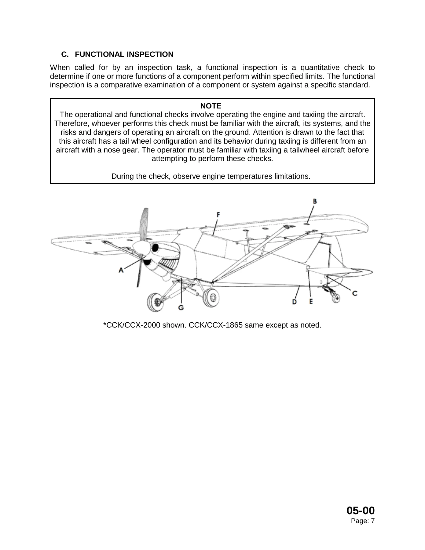
C. FUNCTIONAL INSPECTIONp. 24
3 CONDITION INSPECTION TASKSp. 25
06 Dimensions and Areas Rev NC V2p. 27
1 GENERALp. 31
2 AIRPLANE DIMENSIONS AND AREASp. 32
07 Jacking and Lifting Rev NCp. 35
INTENTIONALLY LEFT BLANKp. 38
1 TOOLS EQUIPMENT AND SUPPLIESp. 39
2 MAINTENANCE PRACTICESp. 39
A JACKING THE AIRPLANEp. 39
(1) RAISING THE TAILp. 39
(a) Set the parking brakes and place chocks under the main wheels.p. 39
(b) Lift under the inboard side of the empennage and raise the airplane to place a tripod or saw horse under the tail wheel springs, as indicated in Figure 1.p. 39
(2) RAISING THE AIRCRAFT FROM THE LANDING GEARp. 40
(a) Place a chock under the opposite main wheel and tail wheel.p. 40
(b) Place a jack under the main axle as shown in Figure 2.p. 40
(3) RAISING THE AIRCRAFT FROM THE WINGp. 40
(a) Place a chock under the opposite main wheel and tail wheel.p. 40
(b) Place jack between the main lift strut wing attachment point and the tie down (Refer to Figure 3). Jack one side at a time. Do not jack both sides simultaneously.p. 40
(4) LIFTING THE AIRCRAFT FROM THE LIFT RINGS (ALL LANDING GEAR CONFIGURATIONS)p. 41
08 Leveling and Weighing Rev NCp. 43
CHAPTER 08p. 43
08 LEVELING AND WEIGHINGp. 45
INTENTIONALLY LEFT BLANKp. 46
1 LEVELINGp. 47
A. PREPARATIONp. 47
Place the aircraft in a hangar with the doors closed where the wind will not affect the aircraft. Lift the empennage, and support the tail wheel on a bench to obtain an approximate flight level attitude. Refer to Chapter 7.p. 47
B. LEVELINGp. 47
(1) LONGITUDINAL LEVELINGp. 47
Secure a spacer block (1.69 ± 0.04 inches) with masking tape to the forward end of a straight edge. Straight edge must be long enough to reach both the forward and aft carry through spars. Support the tail with a saw horse under the tailwheel springs….p. 47
(2) LATERAL LEVELINGp. 47
2 WEIGHINGp. 48
A. GENERALp. 48
B. PREPARATIONp. 48
(a) Clean the aircraft to remove excess dirt and grease.p. 48
(b) Remove the fuel from the aircraft. This may be accomplished by opening the fuel drains until all remaining fuel is drained.p. 48
 Standard range fuel tanks should retain one gallon unusable fuel total.p. 48
 Extended range fuel tanks should retain five gallons unusable fuel total.p. 48
(c) Check that the oil is full.p. 48
(d) Position the pilot’s seat in the middle position.p. 48
C. WEIGHING THE AIRCRAFTp. 49
(a) Place the aircraft on the calibrated scales.p. 49
(b) Level the aircraft as required.p. 49
(c) Record the weight of the main wheels and the tail wheel in Table 1.p. 49
(h) Record new empty weight and position of center of gravity in the POH/AFM, Weight & Balance section and the Equipment List.p. 49
D. WEIGHING THE AIRCRAFT (AMPHIBIOUS FLOATS)p. 50
E. WEIGHING THE AIRCRAFT (STRAIGHT FLOATS)p. 51
10 Parking and Mooring Rev NCp. 53
INTENTIONALLY LEFT BLANKp. 56
1 MAINTENANCE PRACTICESp. 57
A. PARKINGp. 57
(a) Position the airplane on level surface, headed into the wind.p. 57
(b) Set the parking brakes. The parking brake valves are located on the forward portion of the passenger rudder pedals. To engage, press both brake pedals and turn the brake valve on each pedal to the horizontal position.p. 57
(c) Chock the main gear wheels.p. 57
(d) In gusty or stormy weather, moor the airplane.p. 57
(e) When the aircraft is to be parked for an extended time, it should be moved periodically to prevent corrosion in the wheel bearings and flat spots on the tires.p. 57
B. MOORINGp. 57
(a) Position the airplane on level surface, headed into the wind.p. 57
(b) Set the parking brakes. The parking brake valves are located on the forward portion of the passenger rudder pedals. To engage, press both brake pedals and turn the brake valve on each pedal to the horizontal position.p. 57
(c) A good practice is to position the propeller in an angled or horizontal position.p. 57
(d) Chock the main gear wheels.p. 57
(e) There is a tie-down ring underneath each wing next to the forward lift strut (refer to Figure 1). The tail should be tied down by wrapping straps/rope/chains at least once around the tail wheel head (refer to Figure 2). In severe weather, use mult…p. 57
C. STORAGEp. 58
(1) GENERALp. 58
(2) TEMPORARY STORAGE – 30 TO 90 DAYSp. 58
(a) Park and moor the airplane.p. 58
(b) Apply engine preservation. In extremely cold weather, it is advisable to drain the oil sump immediately after stopping for a long period and to warm the oil to 100 F before refilling the sump. To prevent excessive cooling of the oil sump and exces…p. 58
(c) Fill the fuel tanks completely. Check for water accumulating each week.p. 58
(d) Wipe the tires with dry cloth, and treat them with tire protector spray. Mark the tire positions and date with chalk. Turn the wheels and check air pressure regularly.p. 58
(e) Remove the battery and ELT (refer to Chapter 24) and store in accordance with standard practices. Clean the battery compartment and the battery cable terminals to neutralize any battery acid that may be present.p. 58
(f) Lubricate according to lubrication schedule (refer to Chapter 12).p. 58
(g) Clean the propeller to remove dirt, oil, and bug accumulation. A good practice is to position the propeller in an angled or horizontal position.p. 58
(h) Clean and cover the instruments and panel. Observe any additional precautions recommended by the various manufacturers of the avionics and the instruments.p. 59
(i) Clean and install protective covers on the seats.p. 59
(3) INDEFINITE STORAGEp. 59
(a) Park and moor the airplane.p. 59
(b) Apply engine preservation. Refer to the latest edition of the manufacturer’s service letter.p. 59
(c) Drain the fuel tanks (refer to Chapter 28).p. 59
(d) Clean the brake assemblies. The wheels should be turned three to four revolutions per 30 days to prevent corrosion. Touch up all spots where paint has been chipped from the wheels. Wipe the tires with dry cloth, and treat with tire protector spray…p. 59
(e) Remove the battery and the ELT (refer to Chapter 24) and store in accordance with standard practices (refer to Chapter 20). Clean the battery compartment and the battery cable terminals to neutralize any battery acid that may be present.p. 59
(f) Lubricate according to lubrication schedule (refer to Chapter 12).p. 59
(g) Clean the propeller to remove dirt, oil, and bug accumulation. Coat the blades with a corrosion preventive soft compound or film and wrap with moisture proof material. A good practice is to position the propeller in an angled or horizontal position.p. 59
(h) Clean and cover the instruments and the panel. Take any additional precautions according to the manufacturer.p. 59
(i) Clean and install protective covers on the seats.p. 59
(j) Remove all loose equipment and store.p. 59
(k) Clean and install covers over windshield and windows.p. 59
(4) PREPARATION FOR SERVICEp. 59
(a) Engine preparation for service – Refer to the manufacturer’s service letter.p. 59
(b) Remove all covers, tapes and tags from airplane.p. 59
(c) Reinstall the battery and the ELT (refer to Chapter 24).p. 59
(d) Fill the fuel tanks (if applicable) (refer to Chapter 12).p. 59
(e) Thoroughly clean and visually inspect the airplane. It is recommended to carry out at least a 100-hour inspection prior to flying the aircraft (refer to Appendix A).p. 59
(f) Replace O-rings in the fuel selector and (if equipped) engine primer if the fuel system has been left dry for an extended period of time.p. 59
INTENTIONALLY LEFT BLANKp. 60
12 Servicing Rev NCp. 61
INTENTIONALLY LEFT BLANKp. 64
1 GENERALp. 65
2 CONSUMABLE OR FREQUENTLY REPLACED ITEMSp. 66
3 LUBRICATIONp. 67
4 REPLACEMENT TIMESp. 68
The following replacement times are a sample of standard replacement times as recommended by the kit manufacturer and are for use as REFERENCE ONLY.p. 68
5 CONTROL SURFACE TRAVELS AND CABLE TENSION SETTINGSp. 71
6 ENGINE SPECIFICATIONS AND DATAp. 71
6.1 CCK/X-2000p. 71
6.2 CCK/X-1865p. 72
20 Standard Practices Rev NCp. 73
INTENTIONALLY LEFT BLANKp. 76
1 GENERALp. 77
2 DEFINITIONSp. 77
3 TORQUING REQUIREMENTp. 77
4 USE OF TORQUE WRENCHES AND ADAPTERSp. 77
5 TORQUING PATTERNSp. 78
6 SPECIFIC TORQUE REQUIREMENTSp. 78
7 GENERAL TORQUE VALUESp. 79
24 Electrical Power Systems Rev NCp. 81
INTENTIONALLY LEFT BLANKp. 84
1 GENERALp. 85
2 TROUBLESHOOTINGp. 85
(a) Turn all switches off. Use the lowest resistance scale on the DVM. Check the resistance between the battery negative (-) terminal and the engine case. Measurements over 0.5 Ohm should be investigated. Check the engine ground strap and the battery …p. 85
(b) Turn on the master switch. Measure the voltage on the battery bus and on pin + of the regulator. The voltages should be equal, or within 0.2 volts. A difference of more than 0.2 volts may be caused by a bad breaker.p. 85
(c) Try a five pound pull test on all crimp joints and make sure that the terminals are crimped on the wire, not the insulation.p. 85
(d) Troubleshoot systems to determine the root cause of the problem.p. 85
3 ALTERNATORp. 86
A. REMOVALp. 86
(a) Disconnect the wires and remove the mounting bolts.p. 86
B. INSPECTIONp. 86
Inspect the alternator for general condition. Broken wires or damaged connectors may be corrected in the field.p. 86
(b) Check belt for cracking or fraying and replace if defective.p. 86
(c) Inspect the alternator for general condition. Broken wires or damaged connectors may be corrected by qualified personnel.p. 86
C. INSTALLATIONp. 86
(d) Locate the alternator in place.p. 86
(e) Secure the alternator with the mounting bolts; torque the bolts.p. 86
(f) Attach the alternator wires.p. 86
5 MAIN BATTERYp. 86
A. REMOVALp. 86
(a) Remove the pins from each side of pilot’s seat base.p. 86
(b) Slide the seat fully forward and tilt the seat forward.p. 86
(c) Disconnect the battery strap and cables, positive first, then negative. Remove the battery.p. 86
B. INSPECTIONp. 86
(a) Inspect the battery and terminals for condition and corrosion.p. 86
(b) Clean as required.p. 86
(c) If necessary, charge the battery in accordance with the following instructions.p. 86
C. CHARGINGp. 87
The battery may be charged using a 12 volt, 1 ampere battery charger. Charging time using a 1 amp charger is 4.5 hours; charging rate will vary depending on the type of charger used. If a trickle charger is used, charging time may be longer.p. 87
D. INSTALLATIONp. 87
(a) Place the battery in the mounting space. Secure in place with installed strap.p. 87
(b) Connect the positive lead.p. 87
(c) Connect the ground lead.p. 87
(d) Reinstall the pilot’s seat by securing with the pins.p. 87
6 IGNITION BACKUP BATTERYp. 87
A. REMOVALp. 87
(a) Remove right forward interior panel.p. 87
(b) Release four quick-turn fasteners and remove battery cover bracket.p. 87
(c) Remove battery.p. 87
(d) Disconnect terminals.p. 87
B. INSPECTIONp. 87
(a) Inspect the battery and terminals for condition and corrosion.p. 87
(b) Clean as required.p. 87
(c) If necessary, charge the battery in accordance with the following instructions.p. 87
C. CHARGINGp. 88
The battery may be charged using a 12 volt, 1 ampere battery charger.p. 88
D. INSTALLATIONp. 88
(a) Connect negative lead (the black heat shrink covered wire) to battery.p. 88
(b) Connect positive lead (the wire with white silicone tube over it) to battery.p. 88
(c) Place the battery in the mounting space. Place cover over battery and secure four quick turn fasteners.p. 88
(d) Reinstall right forward interior panel.p. 88
7 EMERGENCY LOCATOR TRANSMITTERp. 88
25 Equipment-Furnishings Rev NCp. 89
INTENTIONALLY LEFT BLANKp. 92
1 GENERALp. 93
2 MAINTENANCE PRACTICESp. 94
A. REAR SEAT STOWAGEp. 94
(a) Disconnect the two cinched nylon straps holding the seat cross bar in place. Unscrew and push the screw in to allow the tab to rotate and slide pin out of seat base connector (see Figure 4).p. 94
(b) Remove cross bar from fuselage slots. Slide the seat straps and nylon straps off of the cross bar. Place and secure cross bar in aft storage compartment. Remove cushion from seat (see Figure 5).p. 95
(c) Fold rear seat up and stow in sling seat holder. Place seat cushion and cross bar straps in sling seat holder (see Figure 6).p. 95
(a) Slide the seat straps and nylon straps on the cross bar in the correct order. Install the cross bar into the fuselage slots (see Figure 5).p. 96
(b) Connect the two cinched nylon straps to the floorboard to hold the seat cross bar in place (see Figure 4). Install the seat cushion by lining up the hook and loop tape on the bottom of the seat cushion and top of rear seat.p. 96
(c) Ensure the straps in front of the seat are cinched tight enough to hold cross bar in slots at either end. Ensure the top straps are secure and verify proper routing of straps around fuselage tube and through slide adjuster (see Figure 7).p. 96
B. INTERIOR PANELSp. 97
Figure 8a – Left Side Panelsp. 97
Figure 9b – Removal of Nylon Snap Rivetp. 97
(1) REMOVE LEFT CENTER INTERIOR PANELp. 98
(a) Remove fuel selector handle, gate and fuel selector panel from the left center panel (refer to Chapter 28). Note that the screws for the fuel selector panel have covers over them to be removed first (see Figure 8a).p. 98
(b) Remove the pulley cover on the left side of the floor near the center of the interior panel.p. 98
(c) Remove nylon snap rivets along the bottom edge of the left center panel, and the rivets along the bottom edge of the aft interior panel.p. 98
(d) Remove nylon snap rivets along the vertical seams between left center interior panel and left-aft /left-forward interior panels.p. 98
(e) Open the top of the left center interior panel by slipping a piece of sheet metal (approximately 2” wide and about 2” shorter than the Velcro length) in one end and keep pushing it in, unlocking the Velcro (see Figure 9). Place tape on strap to ho…p. 98
(f) Reach behind left aft interior panel through the lap seam between left center and left aft interior panels. Using a putty knife, unstick the left center panel from the double sided tape along its aft edge (if applicable).p. 98
(g) Remove fasteners securing the pilot’s throttle assembly from the left center panel. There are multiple spacers on each bolt, use care to ensure hardware is not dropped (refer to Chapter 76).p. 98
(h) Remove clevis screw holding the throttle linkage rod to the forward throttle lever. Tape the throttle linkage rod to the panel so it doesn’t puncture the fabric.p. 98
(i) Removed the left forward panel (after all nylon snap rivets are removed) to gain access to the cabin heat intake of the left center panel. Remove the SCAT tubing connected to the composite intake tube (integrated with left center panel).p. 99
(j) Remove left center panel by gently bending the front corner of the panel inward. Pull forward to free the aft edge of the panel then slide the panel aft to clear instrument panel. Lift panel out of aircraft front end first and set aside. It may be…p. 99
(2) OTHER INTERIOR PANELSp. 99
27 Flight Controls Rev NCp. 101
1 GENERALp. 105
2 TROUBLESHOOTINGp. 106
3 PREPARATORY PROCEDUREp. 107
A. LEVELINGp. 107
B. EMPENNAGE RIGGINGp. 107
(1) VERTICAL FINp. 107
(2) HORIZONTAL STABILIZERp. 107
(3) RECORDp. 107
C. DIHEDRAL AND WASHOUTp. 107
4 MAINTENANCE PRACTICESp. 108
A. HORIZONTAL STABILIZERSp. 108
(1) REMOVALp. 108
(2) INSTALLATION (RIGHT)p. 108
(3) INSTALLATION (LEFT)p. 109
(4) HORIZONTAL STABILIZER TRIMp. 109
B. ELEVATORp. 110
(1) REMOVALp. 110
(1) INSTALLATIONp. 110
(3) ELEVATOR RIGGINGp. 111
C. RUDDERp. 112
(1) REMOVALp. 113
(2) INSTALLATIONp. 113
(3) RIGGINGp. 114
D. TAIL BRACE WIRESp. 114
(1) REMOVALp. 114
(2) INSTALLATIONp. 114
(3) RIGGINGp. 115
E. GAP SEALSp. 117
(1) PREPARATIONp. 117
(2) INSTALLATIONp. 117
(3) REMOVALp. 119
F. FLAPSp. 119
(1) REMOVALp. 119
(2) INSTALLATIONp. 120
(e) Secure with a nut and a cotter pin to allow for proper flap and aileron function.p. 120
(3) RIGGINGp. 121
G. AILERONSp. 123
(1) REMOVALp. 123
(2) INSTALLATIONp. 123
(3) RIGGINGp. 124
H. STALL WARNING SYSTEMp. 125
(1) STALL WARNING SWITCH ADJUSTMENTp. 125
28 Fuel System Rev NCp. 127
1 GENERALp. 130
2 STANDARD FUEL TANKSp. 132
Figure 1 – CCK/CCX-1865 Standard Range Fuel Tank Configurationp. 132
Figure 2 – CCK/CCX-2000 Standard Range Fuel Tank Configurationp. 132
3 EXTENDED RANGE FUEL TANKSp. 133
Figure 3 – CCK/CCX-1865 Extended Range Fuel Tank Configurationp. 133
Figure 4 – CCK/CCX-2000 Extended Range Fuel Tank Configurationp. 133
4 SERVICINGp. 134
A. DRAINING FUELp. 134
(a) If your aircraft does not have the additional drain, jack the tail of the aircraft to flight level attitude (Chapter 7 and 8).p. 134
(b) Open the fuel strainer drain valve(s) and allow fuel to drain into container.p. 134
(c) If the fuel has been drained and the aircraft has then been re-fueled, the engine must be run on the ground for enough time to purge the system of air prior to flight.p. 134
5 TROUBLESHOOTINGp. 134
6 FUEL FILTERSp. 135
A. FUEL STRAINER SERVICINGp. 135
(a) Turn fuel selector to “OFF” position.p. 135
(b) Drain fuel from strainer.p. 135
(c) Remove the cotter pin that locks the bowl.p. 135
(d) Place a metal container under the bowl to catch the residual fuel.p. 135
(e) Twist bowl to remove and empty the residual fuel.p. 135
(f) Remove the wire clip ring with fingers and gently remove the screen.p. 135
(g) Inspect and clean the screen.p. 135
(h) Check the condition of the O-ring.p. 135
(i) Carefully install the screen and hold it in place with the wire snap ring.p. 135
(j) Insert and twist the bowl into position.p. 135
(k) Install a new safety cotter pin.p. 135
(l) Turn on fuel and check for leaks.p. 135
B. INLINE FUEL FILTER SERVICING (CCK/CCX-2000 ONLY)p. 136
C. CARBURETOR INLET SCREEN SERVICING (CCK/CCX-1865 ONLY)p. 136
(a) Turn fuel selector to “OFF” position.p. 136
(b) Remove the large hex plug in the left side of the float chamber.p. 136
(c) Clean the screen and flush accumulations of dirt and water from the chamber.p. 136
(d) Install the hex plug.p. 136
7 FUEL SELECTORp. 136
A. FUEL SELECTOR OVERHAULp. 136
(a) Drain the fuel tanks through the drains located on the underside of the fuselage and fuel strainer.p. 136
(b) Drain the remaining fuel out of the fuel strainer drain.p. 136
(c) Remove the selector handle and handle button plate with the springs by loosening the screws (refer to Figure 4).p. 136
(d) Put a rag under the valve to catch any residual fuel.p. 136
Refer to Figure 5.p. 137
(e) Rotate the shaft so the detent balls are between the detent holes.p. 137
(f) Remove the snap ring holding the handle barrel in the housing.p. 137
(g) Carefully pull the barrel out of the housing with fingers positioned to catch each set of balls and springs.p. 137
(h) Remove the small O-ring and the large O-rings, then clean the barrel.p. 137
(i) Inspect for wear and grooves.p. 137
(j) Replace the small O-ring and the large O-rings with new parts and lubricate per Chapter 12 on installation.p. 137
(k) Insert the barrel part way in the housing.p. 137
(l) One set at a time, insert a spring with a ball on each end and push the barrel the rest of the way in.p. 137
(m) Secure with the snap ring.p. 137
(n) Check the operation for positive detent and smooth turning.p. 137
(o) Remove the rag.p. 137
(p) Reattach the cover and the handle stop plate with the springs and the handle.p. 137
(q) Check to make sure the handle stop is working properly.p. 137
8 FUEL PUMPS (CCK/CCX-2000 ONLY)p. 138
A. ENGINE DRIVEN FUEL PUMPp. 138
(a) Turn off fuel selector.p. 138
(b) Remove cowling.p. 138
(c) Drain gascolator.p. 138
(d) Remove inlet and outlet line to/from pump and cap.p. 138
(e)p. 138
(f) Cut safety wire and remove two internal wrenching bolts on fuel pump.p. 138
(g) Maneuver fuel pump out from behind engine.p. 138
(a) Place fuel pump in place behind engine.p. 138
(b) Support fuel pump while bolting into place.p. 138
(c) Replace safety wire.p. 138
(d) Replace inlet and outlet lines to/from pump.p. 138
(e) Turn on fuel selector and check for leaks.p. 138
B. ELECTRIC FUEL PUMPp. 138
(a) Turn off fuel selector.p. 138
(b) Turn off master and pull fuel pump circuit breaker. Remove engine cowl. Remove electric fuel pump shield by removing the two screws on the upper edge. Note that they are screwed into nutplates.p. 139
(c) Drain gascolator sump.p. 139
(d) Remove inlet and outlet lines.p. 139
(e) Locate end of pigtail on fuel pump harness where it joins with engine harness. Unplug connectors on fuel pump wires.p. 139
(f) Remove 4 screws & nuts through the firewall securing fuel pump and Adel clamp for wires.p. 139
(g) Remove fuel pump and fuel filter.p. 139
(h) If replacing fuel pump, remove fittings from pump and install in new pump.p. 139
(a) Ensure fuel pump installed and tighten clamp on mounting bracket.p. 139
(b) Re-install the 4 screws and nuts through the firewall securing fuel pump and Adel clamp for wires.p. 139
(c) Re-connect wire where it joins engine harness.p. 139
(d) Replace inlet and outlet lines.p. 139
(e) Reset breaker, turn on master and verify fuel pressure of pump.p. 139
(f) Reinstall cowl.p. 139
32 Landing Gear Rev NCp. 140
1 GENERALp. 144
Figure 1 – Main Landing Gear, shown with AOSS, CCK/CCX-1865 Shownp. 144
2 TROUBLESHOOTINGp. 145
3 MAIN LANDING GEARp. 147
Figure 2 – Main Landing Gear Arrangement, Bungeep. 147
A. BUNGEE ASSEMBLYp. 147
(1) REMOVALp. 147
(a) Chock the main wheel on the opposite side of the landing gear that is to be worked on. Chock the tail wheel. It is not recommended to perform this work in windy conditions.p. 147
(b) Remove the top bungee cover screws and slide the cover down until the lower bungee bolt is exposed (the bungee cords can be inspected at this point and if replacement is required, accomplish the following steps).p. 147
(c) Jack the aircraft by lifting the wing that is on the same side as the landing gear that is to be worked on. The jack is placed at the forward wing strut to spar attachment point on the desired side (see Chapter 7).p. 147
(d) Remove the upper shock assembly attach bolt and lower the shock assembly.p. 147
(e) Remove the bungee cover end from the shock assembly.p. 147
(f) Remove the lower attach bolt and pull the shock out of the strut.p. 148
(2) INSPECTIONp. 148
(a) Check the bungee cords for broken bands, threads, and signs of weakness. Inspect the hydraulic strut for leaking fluid or damage.p. 148
(b) Replace any hardware that is excessively corroded or worn.p. 148
(3) INSTALLATIONp. 148
(a) Insert the shock assembly in the strut. Insert a bolt with a washer through the shock and strut and place a washer and nut on the end of the bolt. Torque the nut to 160-200 in-lbs.p. 148
(b) Place the bungee cover end over the top shaft of the shock assembly. Align with the top shock hole and the holes in the cabane vee and insert bolt.p. 148
(c) Place the washer and the nut on the end of the bolt. Torque to 130 in-lbs. If necessary, tighten past this torque value to align the nut with the nearest hole in the bolt. Safety the nut with a new cotter pin.p. 148
(d) Verify that all hardware is installed properly, then lower the aircraft back to the ground.p. 148
B. LANDING GEAR LEGp. 148
(1) REMOVALp. 148
(a) Chock the main wheel on the opposite side of the landing gear that is to be worked on. Chock the tail wheel. It is recommended to perform this work in a sheltered hangar.p. 148
(b) Disconnect the brake line from the fuselage.p. 148
(c) Jack the aircraft by lifting the wing that is on the same side as the landing gear that is to be removed. The jack is placed at the forward wing strut to spar attachment point on the desired side (refer to Chapter 7).p. 148
(d) Remove the lower shock strut attach bolt.p. 148
(e) Remove both upper landing gear bolts.p. 148
(2) INSPECTIONp. 148
(a) Inspect the landing gear and fuselage attachment points for cracks, damage, and oversized holes.p. 148
(b) Replace or repair affected parts.p. 148
(c) Inspect the brake backing plates for cracks or excessive wear.p. 148
(3) INSTALLATIONp. 148
(a) Replace any hardware that is excessively corroded or worn.p. 148
(b) Align the upper landing gear attachment holes with the corresponding ones in the fuselage.p. 148
(c) If there is a gap between a landing gear leg and the corresponding fuselage ear, fill the gap with washers of the appropriate thickness.p. 148
(d) Apply grease to slow corrosion and insert the upper landing gear bolts.p. 149
(e) The rear bolt on the right landing gear is longer than the one on the left because the ear of the passenger step must be placed over the bolt end.p. 149
(f) Place washers and nuts on the end of the bolts.p. 149
(g) Align the hole at the bottom of the shock strut with the holes in the landing gear.p. 149
(h) Apply grease to slow corrosion and insert the bolt with a washer under the head. Place washer and nut on the end of the bolt.p. 149
(i) Torque all nuts to 130 in-lbs. or if necessary, past this value so that the nuts may be aligned with the nearest hole on the corresponding bolt.p. 149
(j) Safety the nuts with new cotter pins.p. 149
(k) Verify that all the hardware is installed properly and lower the aircraft to the ground.p. 149
(l) Reconnect the brake lines and tighten the fittings.p. 149
(m) Service the brakes, if needed, to obtain the proper pedal travel.p. 149
C. AOSS GEAR – OPTIONALp. 149
Similar to Bungee Gear. See manufacturer’s maintenance manual.p. 149
4 MAIN WHEELSp. 150
A. REMOVALp. 150
(a) Chock the main wheel on the opposite side of the landing gear that is to be worked on. Chock the tail wheel. Working outside in windy conditions is not recommended.p. 150
(b) Remove the hubcap and the axle nut cotter pin.p. 150
(c) Cut the safety wire and remove the brake back plate bolts.p. 150
(d) Place a jack under the axle and raise the tire off the ground (See Chapter 7).p. 150
(e) Remove the axle nut and wheel.p. 150
(f) The bearings can be removed, cleaned and inspected without disassembling the wheel and removing the tire.p. 150
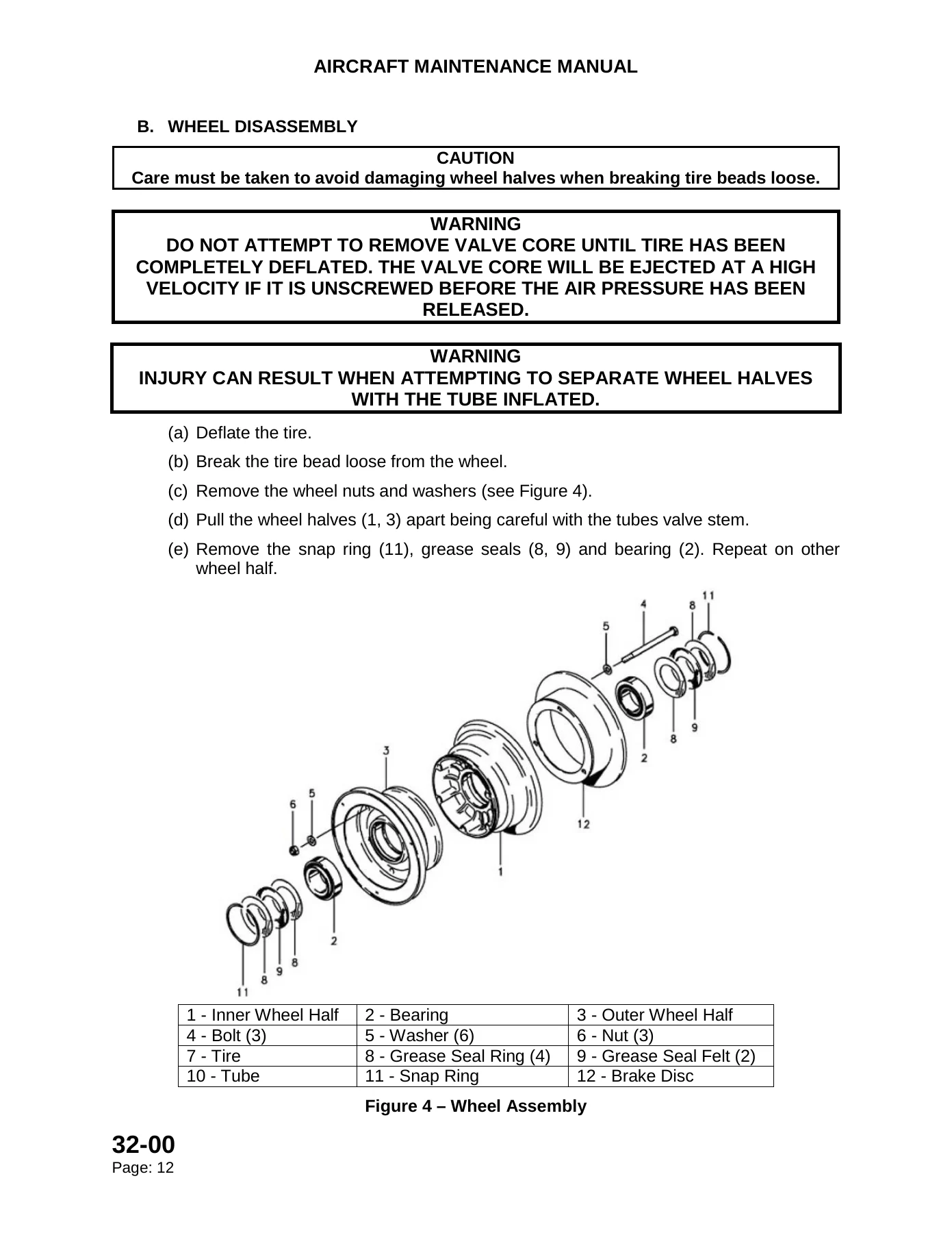
B. WHEEL DISASSEMBLYp. 151
(a) Deflate the tire.p. 151
(b) Break the tire bead loose from the wheel.p. 151
(c) Remove the wheel nuts and washers (see Figure 4).p. 151
(d) Pull the wheel halves (1, 3) apart being careful with the tubes valve stem.p. 151
(e) Remove the snap ring (11), grease seals (8, 9) and bearing (2). Repeat on other wheel half.p. 151
C. INSPECTIONp. 152
(1) AXLEp. 152
(a) Visually inspect the axle to make sure there are no cracks or grooves.p. 152
(2) TIRE AND TUBEp. 152
(a) Visually inspect the tires inside and outside for cuts, uneven or excessive wear, and penetration by foreign objects.p. 152
(b) Visually inspect the inner tube for wear, cuts or cracks. Pay close attention to the valve stem base.p. 152
(c) The tire should be removed when the tread is worn to the base of a groove. Tires with wear through the top fabric layer can only remain in service long enough to return to a maintenance base to be replaced.p. 152
(3) WHEEL HALVES & BRAKE DISCSp. 152
(a) Inspect the wheel halves for cracks or corrosion.p. 152
(b) Inspect the brake disc attachment points for cracking or distortion.p. 152
(c) New disc thickness is .190, minimum disc thickness is 0.170 in.p. 152
(4) BEARINGSp. 152
(a) Clean all metal parts (including the bearings) in a cleaning solution. Dry all parts with compressed air.p. 152
(b) Inspect the bearing and races for wear or damage, replace if necessary.p. 152
(c) Replace unserviceable parts as required.p. 152
D. WHEEL ASSEMBLYp. 152
(a) If a new tire or tube is used or the old one is sticky, dust the inside of the tire lightly with talcum powder.p. 152
(b) Inflate the tube, inside the tire, with enough air to start to fill it out so it will not be pinched between the wheel halves.p. 152
(c) Insert the outboard wheel half (1) over the valve stem and into the tire.p. 152
(d) Mount the inner wheel half (1) onto the outer wheel half (3).p. 152
(e) Secure the brake disc (12) using three bolts (4) with a washer (5) under each head.p. 152
(f) Place a washer (5) and nut (6) on each bolt (4) and torque per Chapter 20.p. 152
(g) Refer to Chapter 12 for proper tire inflation.p. 152
(h) Allow time for the air trapped between the tube and tire to escape and recheck the pressure.p. 152
(i) Pack the bearings with grease (MIL-G-81322E).p. 152
(j) Insert the bearing (4), inner grease seal ring (8), grease seal felt (9), outer grease seal ring (8) and secure with a snap ring (11). Repeat on the opposite side.p. 152
E. MAIN WHEEL INSTALLATIONp. 153
(a) Place the wheel on the axle and tighten the axle nut so the tire will turn 1 ½ -2 times after a good spin.p. 153
(b) Safety with a cotter pin.p. 153
(c) Verify the tire pressure (Chapter 12).p. 153
(d) Safety the axle nut with a cotter pin. Verify before attaching the hubcaps.p. 153
(e) Position the brake back plates, insert the bolts, and torque to 65-75 in-lbs.p. 153
(f) Safety the bolts in pairs with 0.032 safety wire.p. 153
(g) Lower the aircraft to the ground.p. 153
5 BRAKE CALIPERSp. 153
A. REMOVALp. 153
(a) Refer to Figure 5. Cut the safety wire (1) and remove the brake back plate bolts (2).p. 153
(b) Disconnect the brake line (3) from the caliper (4).p. 153
(c) Separate the caliper (4) from backing plate (5).p. 153
B. INSPECTIONp. 153
(a) Inspect the brake linings for loose rivets, cracks and uneven wear. The minimum lining thickness is 0.100 inches.p. 153
(b) Inspect the calipers for leaks and excessive corrosion. If leaks are present at the pistons, overhaul the caliper.p. 153
(c) Inspect the brake backing plate for cracks or excessive wear.p. 153
C. INSTALLATIONp. 154
(a) Position the brake pressure plate on the caliper so the linings are facing the disc.p. 154
(b) Insert the caliper anchor lugs (6) into the backing plate (5) holes.p. 154
(c) Connect the brake line (3) and tighten. Make sure the wheel turns freely.p. 154
(d) Position the brake back plates (7), insert the bolts (2), and torque to 65-75 in/lbs.p. 154
(e) Safety (1) bolts (2) with 0.032 safety wire.p. 154
(f) Make sure the wheel turns freely.p. 154
6 MASTER CYLINDER AND PARKING BRAKE VALVEp. 154
A. REMOVALp. 154
(a) Drain hydraulic fluid from system.p. 154
(b) See figure 6. Disconnect brake line from 90 Brass Poly-Flow Fitting (4).p. 154
(c) Remove Cotter Pins (10) (11) from Clevis Pins (8) (9).p. 154
(d) Remove Clevis Pins (8) (9) and AN960-10 Washers (12).p. 154
(e) Remove Master Cylinder (1) and attached components.p. 154
B. INSPECTIONp. 155
(a) Inspect Master Cylinder (1) for signs of leaks, cracks, or any other damage.p. 155
(b) Inspect Brake Reservoir (6) for signs of leaks, cracks, or any other damage.p. 155
(c) Inspect all fittings (2) (3) (4) (5) for signs of leaks, cracks, or any other damage.p. 155
C. INSTALLATIONp. 155
(a) See Figure 6. Ensure center to center distance of bottom hole to upper hole on Master Cylinder (1) is 5.125”. Adjust distance as required by twisting nut on Master Cylinder arm.p. 155
(b) Ensure Master Cylinder lock nut is tight.p. 155
(c) Locate Master Cylinder (1) on rudder pedal as shown in Figure 6.p. 155
(d) Insert Clevis Pin (9) thru rudder pedal, AN960-10 Washers (12), and bottom of Master Cylinder (1).p. 155
(e) Insert Clevis Pin (8) through rudder pedal and top of Master Cylinder (1) arm.p. 155
(f) Secure both clevis pins (8) (9) with Cotter Pins (10) (11).p. 155
(g) Connect brake line to 90 Brass Poly-Flow Fitting (4).p. 155
(h) Fill brake system with MIL-H-5606 hydraulic fluid. Bleed system carefully ensuring no air is left in the brake lines. Top off Brake Reservoir (6) making sure that it is a minimum of ¾ full.p. 155
(i) If any fittings are replaced, seal all pipe threads with Loctite 567.p. 155
7 TAIL LANDING GEARp. 156
A. 3200-TYPE STEERABLE TAIL WHEELp. 156
(1) INSPECTIONp. 156
(a) Refer to Figures 8 and 9. Check the leaf springs for damage or twisting.p. 156
(b) Inspect the arm assembly, flat spring, fork, and bracket for excessive wear, cracks or other damage. Replace damaged parts.p. 156
(c) Examine the thrust washers for wear, scoring, or other damage. Inspect the bearing and races for wear or damage.p. 156
(d) Wipe the tire and the tube with a dry cloth. If the tire or the tube is spotted with grease, oil or other deposits, wash in a solution of soap and water. Rinse with clean water and dry with a clean cloth.p. 156
(e) Visually inspect for cuts, uneven or excessive wear, and penetration by foreign objects. Replace if the tire is in poor condition. The tire should be removed when the tread is worn to the base of a groove. Tires that are worn through the top fabri…p. 156
(2) REMOVALp. 156
(a) Lift the tail section of the airplane and rest the fuselage on a bench so the tail landing gear clears the ground.p. 157
(b) Disconnect the chain links from the tail wheel arms.p. 157
(c) Remove the front tail spring attach nut and washer.p. 157
(d) Disconnect the tail spring clamp by removing the nuts, washers, and bolts.p. 157
(e) To separate the springs from the tail wheel, remove the large area nut, washers, and bolt.p. 157
(f) The components that make up the tail wheel assembly may not be repaired except minor realignments are permitted, such as minor dents and bends.p. 157
(3) DISASSEMBLYp. 157
(a) Refer to Figure 8. Remove the tire assembly from the fork by removing the cotter pin (1), castle nut (23), and washer (3) then sliding the axle (21) out.p. 158
(b) At the bottom of the fork (4) remove the cotter pin (1), short castle nut (2), and washer (3). Carefully pull the fork (4) off of the bracket (13).p. 158
(c) Separate the spacer (22), grease retainer (14), and the bearing (15) from the fork (4).p. 158
(d) Disengage the lower dust cap (5), thrust washer (7), arm assembly (8), thrust washer (7), pawl (6), upper dust cap (9), springs (10), thrust plate (11), and fiber thrust plate (12) from the fork (4) and bracket (13).p. 158
Figure 9 – Tail Wheel Assemblyp. 158
(e) Deflate the tube (11) (see Figure 9).p. 158
(f) Break the tire bead loose from the wheel.p. 158
(g) Remove the wheel half nuts (5) and bolts (6).p. 158
(h) Pull the wheel hubs (8) apart being careful with the valve stem.p. 158
(i) Remove the spacer (1), grease retainer (2), inner spacer (3) and bearing (4) from each hub.p. 158
(j) Visually inspect the inner tube for wear, cuts or cracks taking a close look at the valve stem base. Replace if the tube is in poor condition.p. 159
(k) Inspect the bearing and races for wear or damage. Replace if necessary.p. 159
(4) CLEANINGp. 159
(5) REASSEMBLYp. 159
(a) Refer to Figure 8. Hand apply grease to all internal parts and pack the bearing (15) with grease (MIL-G-81322E).p. 159
(b) Place the lower dust cap (5) on the fork (4) and the thrust washer (7) on the fork (4) being sure to align the notch with the locking pin in the fork (4).p. 159
(c) Position the pawl (6) on the arm (8) with the longest lobe down and place the arm assembly (8) on the fork (4).p. 159
(d) Position the other thrust washer (7) and the upper dust cap (9) on the arm assembly (8).p. 159
(e) Insert 3 springs (10) in the proper holes on the top of the fork (4) so the thrust plate (11) can be placed on top.p. 159
(f) Position the fiber thrust plate (12) in the bracket (13) so the nub is aligned with the groove and insert the bracket assembly (13) into the fork (4) maintaining the alignment of all the interlocking parts.p. 159
(g) Place the bearing (15), grease retainer (14), spacer (22), and washer (3) in the fork (4). Exert pressure on the bracket (13) to engage the short castle nut (2) with the bracket assembly post.p. 159
(h) Tighten the nut (2) securely, back off to the first cotter pin hole in the bracket post, and secure with a cotter pin (1). These last steps may be accomplished once the tail wheel assembly is installed back on the fuselage.p. 159
(i) Check to verify proper tail wheel pivoting and tension.p. 159
(j) Install the tire assembly on the fork by sliding the axle (21) with the lock washer (20) through the fork and tire assembly.p. 159
(k) Secure with a washer (3) and castle nut (23). Tighten the nut until there is no free play in the bearings and there is a slight amount of friction. Safety with a cotter pin (1).p. 159
(l) Pump the tail wheel bracket assembly (13) and axle (21) full of grease (MIL-G-81322E) then wipe off the excess.p. 159
(6) INSTALLATIONp. 160
(a) See Figure 7. Position the tail wheel springs on the fuselage with long bolt and hold in place with a washer and a nut.p. 160
(b) Install the small bolts, clamp, and small washers with the small nuts only finger tight.p. 160
(c) Insert the bushing into the tail wheel assembly, if they were removed.p. 160
(d) Insert the bolt through the bushings and tail wheel assembly.p. 160
(e) Hold in place with washer and large area nut.p. 160
(f) Tighten the large area nut to 270-300 in-lbs. Tighten the small nuts to 70-100 in-lbs.p. 160
(g) Reconnect the chain links to the tail wheel arms. The springs and chains should neither be slack nor have tension when the wheel is centered. It may be necessary to adjust the number of chain links to achieve this.p. 160
(h) Lower the tail section to the ground.p. 160
8 CLAMAR 2180 AMPHIBIOUS FLOATSp. 160
9 INTENTIONALLY LEFT BLANKp. 161
33 Lights Rev NCp. 162
INTENTIONALLY LEFT BLANKp. 165
1 GENERALp. 166
2 CABIN LIGHTINGp. 166
3 LANDING AND TAXI LIGHTSp. 166
A. REMOVALp. 166
(a) Remove six screws holding the lens in place, breaking the silicone seal. Remove the lens.p. 166
(b) Remove two screws and the lamp assembly. Disconnect wiring.p. 166
B. INSTALLATIONp. 166
(a) Attach wiring; note the polarity must be correct for the LED light. Reposition front mounting plate and secure with two screws.p. 166
(b) Reattach the lens. Use care not to crack the Plexiglas. Use silicone as required to reseal the lens in place.p. 166
4 LIGHTWEIGHT LED NAVIGATION LIGHTS AND ANTI-COLLISIONp. 167
34 Pitot Static Rev NCp. 168
INTENTIONALLY LEFT BLANKp. 171
1 GENERALp. 172
This section covers the Pitot and Static systems. These systems provide the information required by the airspeed indicator, the altimeter, the vertical speed indicator and the altitude encoder.p. 172
The pitot system senses dynamic pressure through a tube that is aligned with the flow of air and is located under the left wing or the leading edge of the left front jury strut.p. 172
The static pressure ports are located on both sides of the fuselage, on the boot cowl. There are two ports to counteract the effects of yaw.p. 172
Figure 4 – Dynon D180 Instrument Panelp. 173
Figure 5 – World VFR Instrument Panelp. 174
Figure 6 – MyPanel Instrument Panelp. 174
Figure 7 – Standard Instrument Panelp. 175
2 TROUBLESHOOTINGp. 176
3 MAINTENANCE PRACTICESp. 177
A. ATC TRANSPONDER TESTp. 177
A transponder test is required every 24 calendar months in accordance with 14 CFR 91.413.p. 177
B. ALTIMETER STATIC SYSTEM TEST AND INSPECTIONp. 177
Static system tests must comply with the requirements of 14 CFR 91.411 and be performed by a rated repair station with the appropriate test equipment. A static leak test should be accomplished whenever a connection has been loosened or an instrument r…p. 177
C. STATIC SYSTEM LEAK TESTp. 177
Connect the test equipment directly to a static port and seal off the opposite static port with plastic tape.p. 177
Apply a vacuum equivalent to 1,000 feet altitude, (differential pressure of approximately 1.07 inches of mercury or 14.5 inches of water) and hold. After 1 minute, check that a leak has not exceeded the equivalent of 100 feet of altitude (decrease in …p. 177
D. PITOT SYSTEM LEAK CHECKp. 177
Seal the drain hole on the bottom of the pitot tube and connect the pitot pressure opening to a tee to which a source of pressure and manometer or reliable indicator is connected.p. 177
Restrain the hoses to prevent them from moving excessively when the pressure is applied.p. 177
Apply pressure until the airspeed indicator indicates 100 MPH. (87 KTS) (equivalent to a differential pressure 1.1 inches of mercury or 14.9 inches of water). Hold this pressure and clamp off from the source of pressure. After 1 minute, the leakage sh…p. 177
Inspect the hoses for signs of deterioration, particularly at bends and at the connection points to the pitot mast and airspeed indicator. Replace any hoses that are cracked or hardened. Any time a hose is replaced, perform a pressure check. Unseal th…p. 177
39 Electric Panels Rev NCp. 178
INTENTIONALLY LEFT BLANKp. 181
1 GENERALp. 182
2 INSTRUMENTSp. 185
3 COM SYSTEMp. 185
A RADIOp. 185
B INTERCOMp. 185
4 NAVIGATION SYSTEMp. 185
A TRANSPONDERp. 185
B GPSp. 185
5 ANTENNA LOCATIONSp. 186
A COM ANTENNAp. 186
B TRANSPONDER ANTENNAp. 186
C GPS ANTENNAp. 186
51 Repair of Structure & Components Rev NCp. 188
INTENTIONALLY LEFT BLANKp. 191
1 GENERALp. 192
2 PATCHING HOLES IN FABRIC COMPONENTSp. 192
Refer to Polyfiber Procedure Manual or Stewart Systems Fabric Covering and Finishing Procedures Manual for fabric repair instructions.p. 192
3 NON-STRUCTURAL SHEET METAL REPAIRSp. 192
A. LEVEL OF CERTIFICATIONp. 192
B. AUTHORIZED NON-STRUCTURAL SHEET METAL REPAIRS.p. 192
4 NON-STRUCTURAL COMPOSITE MATERIALS REPAIRSp. 192
A. LEVEL OF CERTIFICATIONp. 192
B. AUTHORIZED NON-STRUCTURAL COMPOSITE MATERIALS REPAIRSp. 192
5 STRUCTURAL REPAIRSp. 192
A. AUTHORIZED STRUCTURAL REPAIRSp. 192
Repair all tubular structures per Aircraft Circular 43.13. Reference chapter 5 for inspection procedures. For all structural repairs submit an MRA request form to Cub Crafters, Inc. see section 5.B belowp. 192
B. MAJOR REPAIR AND/OR ALTERATIONS (MRA) REQUESTSp. 192
For any and all major repairs or alterations, contact Cub Crafters, Inc. to obtain and submit a Major Repair and/or Alteration (MRA) request from.p. 192
53 Fuselage Rev NCp. 194
INTENTIONALLY LEFT BLANKp. 197
1 GENERALp. 198
The stabilizers, elevators, and rudder are constructed of tubular steel with steel channel ribs. Stainless steel tie rods and fittings brace the horizontal stabilizers to the vertical stabilizer and fuselage.p. 198
2 MAINTENANCE PRACTICESp. 198
A. REPAIRp. 198
INTENTIONALLY LEFT BLANKp. 199
57 Wings Rev NCp. 200
INTENTIONALLY LEFT BLANKp. 203
1 GENERALp. 204
The wing is covered with fabric, has two extruded aluminum spars, formed aluminum ribs, and aluminum leading and trailing edge skins. Rigidity is provided by drag wires and drag braces. The left or right wing panels may house optional landing lights. …p. 204
2 MAINTENANCE PRACTICESp. 204
A. WINGp. 204
(1) REMOVALp. 207
(a) Remove the front wing root fairing, rear wing root fairing, wing/root panel interface, skylight, and turtle deck.p. 207
(b) Drain the fuel tank(s). Disconnect fuel supply and gauge lines inboard ends at the wing root. Cover all exposed ends of tubing and hoses with tape to prevent contamination of the fuel from dirt or debris.p. 207
(c) Disconnect the pitot air tube at the wing root.p. 207
(d) Disconnect the appropriate wiring, stall warning system, navigation, and landing light at the wing root butt splices.p. 207
(e) Disconnect the top aileron cable from the top aileron horn.p. 207
(f) Remove wing pulley inspection plate covers from the wing. Remove pulley and aileron upper cable attachment. Remove lower aileron pulley cover and pulley in the fuselage.p. 207
(g) Remove fairleads from wing strut. Disconnect the lower aileron control cables from the torque tube link below the control stick.p. 207
(h) If the wings are to be completely removed, disconnect and remove the upper aileron crossover cable.p. 207
(i) Disconnect the flap control rod from the flap lever arm and flap. Remove flaps.p. 207
(j) Unbolt and remove the jury strut braces. They are secured to the wing from the middle of the struts. Mark the struts LH and RH so they may be reinstalled in the same location.p. 207
(k) With a person holding the wing and one person holding the rear lift strut, remove the lower and upper rear lift strut bolts and separate the strut from the fuselage.p. 207
(l) Remove the nuts from the wing and strut attachment bolts.p. 207
(m) Remove the lower and upper front lift strut bolts and separate the strut from the fuselage.p. 207
(n) Remove the wing from the fuselage.p. 207
(o) Rest the wing on the leading edge using soft pads along the leading edge or place horizontally on padded sawhorses so as not to dent or damage the surfaces.p. 207
(p) Repeat all the procedures on the opposite wing, if necessary.p. 207
(2) INSTALLATIONp. 208
(a) Support the wing at the outboard end and at the wing root. Align the wing root attachment points with the fuselage attachment points and insert bullets. (It is easier to temporarily secure the wing with bullets of the same diameter as the bolts an…p. 208
(b) Position front strut fork on the fuselage attachment point and align the hole with a bullet.p. 208
(c) Align top hole of the front strut with the wing attachment hole and secure with a bullet.p. 208
(d) Position rear strut fork on the fuselage attachment point, align the hole with a bullet; align top hole of the rear strut with the wing attachment point and secure with a bullet.p. 208
(e) Repeat the procedure on the opposite wing, if necessary.p. 208
(f) Apply a light coat of grease to the wing attachment bolts before installation.p. 208
(g) Press out the bullets at the wing to fuselage attachment points with the proper bolts. Secure the bolts using the appropriate washers and nuts. Torque the nuts to 160-200 in. lbs. (refer to Chapter 20).p. 208
(h) Press out the bullet at the wing to front strut attachment point with the proper bolt. Slide the spacer and pulley bracket over the end and secure the bolt using the appropriate washer and nut. Torque to 160-200 in. lbs. (refer to Chapter 20).p. 208
(i) Press out the bullet at the wing to rear strut attachment point with the proper bolt. Secure using the appropriate washer and nut. Torque to 160-200 in. lbs. (refer to Chapter 20).p. 208
(j) Support the outboard end of the wing and remove the lower strut bullets. Insert the proper bolts. Torque the nut to 95 in. lbs., torque up to the nearest castellation, and safety with a cotter pin. Ensure the strut fork jam nuts are tight.p. 208
(k) Check the dihedral angle and wing washout per Section 3. Adjust if necessary.p. 208
(l) Install the jury struts making sure the longer vertical tube is in front. Secure using the appropriate bolt, washer, and nut then torque the top bolt to 38-43 in. lbs., bottom bolt to 23-28 in. lbs.p. 208
(m) Connect upper aileron and the crossover upper cables to aileron horns.p. 208
(n) Connect the flap to the flap control rod. Connect the control arm to the flap handle lever.p. 208
(o) Route the lower aileron cable down the strut.p. 208
(p) Install the associated pulley and fairleads. Make sure the cable is not hooked on a strut.p. 208
(q) Connect the lower aileron control cables to the torque tube link. Ensure that the nuts have the appropriate cotter pins. Reinstall lower aileron pulley covers.p. 208
(r) Connect the pitot air tube at the wing root. Reconnect the stall warning system, navigation, and landing light wires at the wing root.p. 208
(s) Remove the tape from the fuel line ends. Reconnect the fuel supply and gauge lines at the wing root. Torque the ¼ inch hose clamps to 10-14 in. lbs. Reconnect plastic fuel line fittings, torque to finger tight plus 1 ½- 2 additional revolutions.p. 208
(t) Ensure that the aileron cables are not rubbing or hung up. Check to verify the cable tension is 40 ± 5 lbs. and adjust in accordance with Chapter 27. Install the wing pulley inspection plate covers.p. 209
(u) Reinstall front and rear wing root, turtle deck, skylight, and wing/root panel interface.p. 209
3 RIGGING THE WINGSp. 209
A. PREPARATIONp. 209
The aircraft must be level longitudinally and laterally prior to setting or adjusting the dihedral or the washout angles. Refer to the leveling procedure described in Chapter 8.p. 209
B. DIHEDRAL ANGLEp. 209
(a) Remove the front wing root fairings.p. 210
(b) Stretch a string from wing tip to wing tip above the front spar and pull tight and secure.p. 210
(c) Measure down from the string to the top of the inboard edge of the front spar cap (Figure 4). The measurement should be 3 inches ± 0.13 (1/8) inches. This adjustment is accomplished by turning the forks of the lower end of the front strut in or out.p. 210
(d) To determine that each wing panel has the same dihedral, hold a straightedge on the end of a 30-inch level so that one end of the straightedge protrudes 0.41 (13/32) of an inch above the level (see Figure 4). Place the level combination along the …p. 210
(e) If the dihedral angle is not equal for both wing panels, adjust the threaded fork on the lower end of the front strut until dihedral angle is the same. Recheck the total dihedral and readjust as necessary.p. 210
(f) Record the actual results in the aircraft logbook.p. 210
(g) NOTE: Rigging of the wings is not complete until the washout angle is set.p. 210
C. WASHOUT ANGLEp. 211
(a) Check the washout of each wing by holding a straightedge on the end of a 30-inch level so that one end of the straightedge protrudes 0.38 (3/8) inches above the level (see Figure 4). Place this combination along the bottom surface of the full rib …p. 211
(b) To obtain the proper washout, adjust the threaded fork at the lower end of the rear strut at the fuselage end until the bubble is centered.p. 211
(c) Repeat on the opposite wing if needed.p. 211
(d) Record the actual results in the aircraft logbook.p. 211
4 VORTEX GENERATORSp. 211
(a) Ensure that the area where the vortex generator fell off is dry and free of grease and dirt.p. 211
(b) Clean the bottom surface of the vortex generator, removing any old adhesive.p. 211
(c) Mask off the rectangular footprint of the vortex generator.p. 211
(d) Reattach the vortex generator with Loctite Depend® glue.p. 211
(e) Remove masking and wipe off excess glue with cleaner.p. 211
60 Propeller Rev NCp. 212
(a) Check that the mounting face of the propeller is tight against the engine flange and check the blade track.p. 216
(b) Verify that the attaching bolts have reached their required torque and have not bottomed out of the threads.p. 216
(c) Remove the propeller, rotate it 180 degrees on the engine crankshaft flange, and re-install. Again, check the blade track.p. 216
(d) If roughness or vibration is still present, dynamic propeller balancing may be required.p. 216
(e) Inspect engine installation to verify clearance between engine mount, exhaust and cowling.p. 216
(a) Turn ignition switch to OFF, and ensure that the ignition and starter circuit breakers are pulled.p. 216
(b) Remove the spinner and retain all fasteners.p. 216
(c) Cut and remove the safety wire from the propeller bolts.p. 216
(d) Remove the propeller bolts. Assistance may be needed to hold the propeller and aft spinner bulkhead.p. 216
(a) Examine the propeller blades for corrosion, cracks, nicks, or dents beyond permissible limits found in the propeller manufacturer’s service manuals. If the propeller is unserviceable, replace it with a new one and return the damaged propeller to t…p. 217
(b) Remove the spinner. Inspect the attaching bolts for worn or damaged threads and heads. Replace damaged bolts with new ones.p. 217
(c) Inspect the spinner bulkheads for cracks or broken brackets. Replace if any damage is noted.p. 217
The following instructions are a general guide. Refer to propeller manufacturer’s detailed instructions as required.p. 217
(a) Thoroughly clean the surfaces of the crankshaft flange and pilot stub, the rear/mounting face of the propeller, and the pilot bore. Carefully examine each surface and especially examine the end of the crankshaft pilot stub; minor nicks or burrs mu…p. 217
(b) Ensure the propeller attaching bolts and the threads in the drive bushings or retaining nuts are clean and dry.p. 217
(c) Turn ignition switch to OFF, and ensure that all circuit breakers are pulled.p. 217
(d) Place the spinner backing plate on the crankshaft flange ensuring the prop blade orientation is correct.p. 217
(e) Position the propeller in the correct orientation. Tighten the bolts snug and ensure the spinner backing plate is positioned properly on the flange bushings before torquing the bolts.p. 217
(f) Apply torque in several increments, working diagonally across the bolt circle until reaching proper torque.p. 217
(g) Check to make sure the propeller track is within 1/8-inch.p. 217
(h) Install 0.041-inch diameter stainless steel safety wire in the propeller bolt heads locking bolt heads together in a tightening moment. Bolts should be wired in pairs, twisting the wire between the bolt heads.p. 217
71 Powerplant Rev NC
INTENTIONALLY LEFT BLANK
1 GENERAL
Figure 1 – Engine Mount Assembly (Shown with CC340 Engine)
2 TROUBLESHOOTING, SERVICING, AND MAINTENANCE
3 ENGINE COWLING
A. INSPECTION
Inspect the cowl for loose rivets, wear points and cracks.
B. REMOVAL
(a) Remove screws along lower access panel. Be sure to hold on to the air filter so it does not fall to the ground.
(b) Carefully remove the lower access panel with the air filter.
(c) Disconnect the induction tube and cabin heat air inlet.
(d) Remove and retain the screws holding the upper cowl to the lower cowl and the fuselage.
(e) Carefully remove the upper cowl.
(f) Remove the screws holding the lower cowl to the fuselage.
(g) Carefully remove the lower cowl.
Figure 2 – Lower Access Panel, CCK/CCX-1865 Shown, CCK/CCX-2000 Similar
C. COWL FLAP POSITION ADJUSTMENT, CCK/CCX-1865 ONLY
(a) While lower cowl is detached, remove aft screws from the top and bottom of each cowl flap.
(b) Adjust cowl flap position.
(c) Install aft screws on the top and bottom of each cowl flap.
(d) Reinstall lower cowl as directed in Installation.
D. INSTALLATION
(a) Carefully position the lower cowl in place; secure the cowl to the fuselage with screws.
(b) Carefully position the upper cowl in place; secure it to the lower cowl and to the fuselage with screws.
(c) Make sure the seal around the inlets is properly positioned around the inlet openings.
(d) Double check to make sure all the hardware is tight.
(e) Connect SCAT tubing to cabin heat air inlet in cowl.
(f) Reinstall the induction tubing, ensure hose is secure. Do not overtighten.
(g) Carefully position the lower access panel in place. Secure the lower access panel to the lower cowl with screws.
(h) Verify there is clearance between the cowl and prop spinner.
Figure 3 – Engine Cowl Installation, CCK/CCX-1865 Shown, CCK/CCX-2000 Similar
4 AIR INDUCTION
5 AIR FILTER
A. REMOVAL
(a) Remove screws holding the lower access panel to the lower cowl.
(b) Remove lower access panel with air filter.
B. INSPECTION
(a) Inspect the foam filter for any damage, such as tears or large holes. If a new filter is required, contact the kit manufacturer for replacement filter part number PC54108-001 (CCK/CCX-1865), or XC53110-001 (CCK/CCX-2000).
(b) Clean the filter in a mild degreasing cleanser to remove dirt and other particles. Wring the excess from the element and allow it to dry.
(c) Apply filter oil, such as Castrol Foam Filter Oil or Amsoil High Tack Foam Filter Oil, to the element and work it into the 7ells throughout.
C. INSTALLATION
(a) Align air filter with opening in lower access panel.
(b) Carefully position lower access panel on to lower cowl. Make sure air filter is inside lower access panel.
(c) Secure lower access panel to lower cowl with screws.
6 AIR INLET PLENUM (CCK/CCX-2000 ONLY)
A. REMOVAL
(a) Loosen 8X hose clamps on the rubber couplings at the induction tubes.
(b) Slide the rubber couplings down the induction tubes, away from the plenum.
(c) Remove the attachment hardware connecting the air inlet plenum to the fuel injection servo.
B. INSPECTION
(a) Inspect plenum for cracks or visible damage.
(b) Inspect the induction tubes for any signs of slippage or disconnection at the cylinder attachment.
C. INSTALLATION
(a) Re-install the attachment hardware at the fuel injection servo. Torque bolts to 120-145 IN-LBS and safety wire the bolt heads.
(b) Slide the rubber couplings into place at the plenum to induction tube interface.
(c) Tighten 8X hose clamps around the rubber couplings.
7 CARBURETOR (CCK/CCX-1865 ONLY)
A. INSTALLATION OF CABLE TO VALVE ARM SWIVEL FITTING
(a) Insert the carburetor heat control cable end through the swivel fitting stud.
(b) Insert the threaded end of the stud through the swivel fitting and through the carburetor heat valve arm.
(c) Place the washer and castle nut on the stud and tighten it one half turn past finger tight. NOTE: Do not over or under tighten as this can adversely affect actuation.
(d) Test the travel of the carburetor heat control knob in the cockpit and adjust the position of the cable within the fitting. When the position is correct, tighten the castle nut until the cable is close to bottoming out on the swivel, then install …
B. REMOVAL
(a) Turn fuel selector to “OFF”
(b) Remove engine cowling.
(c) Remove safety wire and the four bolts holding the carburetor air box to the bottom of the carburetor. Discard used lock washers.
(d) Disconnect fuel inlet line from the fitting on the carburetor and install a temporary plug to prevent fuel line contamination.
(e) Remove the cotter pin and disconnect the throttle cable from the carburetor arm by removing the bolt and washer(s) (refer to Chapter 76).
(f) Remove the cotter pin and disconnect the mixture cable swivel from the carburetor arm by removing the nut and washers from the swivel stud.
(g) Remove four of each: nuts, lock washers, and washers holding the carburetor to the bottom of the oil pan. Discard used lock washers and gasket.
C. INSTALLATION
(a) Install the carburetor on the bottom of the oil pan using a new gasket, washers, new lock washers, and nuts.
(b) Connect the mixture cable and safety in place (refer to Chapter 76).
(c) Connect the throttle cable and safety.
(d) Remove the temporary plug from the fuel line and briefly turn the fuel selector handle to “BOTH” to flush the line of possible contaminants. Collect the fuel in an appropriate container.
(e) Inspect the screen in the fuel strainer, clean if needed. Reassemble and safety (refer to Chapter 28).
(f) Reinstall the carburetor air box on the bottom of the carburetor. Use new lock washers and safety wire.
(g) Reconnect fuel line to the fitting on the carburetor. Ensure it will not contact the cowling, cowl flaps, or the exhaust pipe.
(h) Turn fuel selector to “BOTH” and verify there are no leaks.
D. VERIFICATION
Perform ground run and leak check.
A. REMOVAL
(a) Disconnect all fittings, inlet and outlet fuel lines, from the servo.
(b) Disconnect all control cables from the servo.
(c) Remove fasteners connecting the servo to the intake hanger bracket.
(d) Remove fasteners connecting the servo to the aft servo bracket mount.
(e) Carefully remove servo.
B. INSTALLATION
(a) Install servo to the attach brackets that it was removed from. Install hardware in the same orientation that it was removed.
(b) Reconnect all fittings and control cables. NOTE: Do not over or under tighten the control cable castle nut on the stud as this can adversely affect actuation.
C. TROUBLESHOOTING
9 SUPERIOR XP360 & LYCOMING 363i (CCK/CCX-2000 ONLY)
74 Engine Ignition Rev NCp. 233
Remove spark plug caps and spark plugs. Inspect the firing end of the spark plugs for any foreign material lodged between electrodes or around the insulator that could be conductive, clean as required.p. 237
Check the electrode gap per the manufacturer specifications and re-set if necessary. Check connector for any abnormalities and clean if needed. Refer to the latest revision of Light Speed Engineering, INSTALLATION AND OPERATION MANUAL For PLASMA III, …p. 237
Apply a small amount of Spark Plug Thread Lubricant to the threaded area of each spark plug at the firing end. Install the plugs and torque to 15 ft/lb. Connect the spark plug caps.p. 237
Refer to the latest revision of Light Speed Engineering, INSTALLATION AND OPERATION MANUAL For PLASMA III, II+, and I CDI SYSTEMS.p. 237
76 Engine Controls Rev NCp. 239
INTENTIONALLY LEFT BLANKp. 242
1 GENERALp. 243
2 MAINTENANCEp. 244
A. THROTTLE CABLE ASSEMBLYp. 244
Figure 1 – Throttle Installation, CCK/CCX-1865 & CCK/CCX-2000 (Forward Throttle Shown)p. 244
B. LEVER ATTACHMENTp. 245
C. LEVER INTERCONNECT LINKAGEp. 245
D. ATTACHMENT OF THROTTLE CABLE TO SIDE PANELp. 246
E. MOTOR MOUNT THROTTLE CABLE ATTACHMENTp. 247
F. THROTTLE CABLE TO CARBURETOR ARM ATTACHMENTp. 249
The throttle cable is secured to the carburetor arm with a bolt, through-bushings, a washer, a castle nut, and a cotter pin.p. 249
The throttle travel can be adjusted by screwing the bearing rod end. Be sure that the bearing rod end jam nut is retightened after making any adjustment.p. 249
G. INSPECTIONp. 249
(a) Ensure that the throttle arm at the carburetor contacts both stops at either extreme of its travel while the throttle levers in the cabin have positive clearance from the panel.p. 249
(b) Move the throttle to either full open or full closed, inspect cable attachment at the carburetor. Repeat the same procedure with the full opposite throttle setting.p. 249
(c) Ensure that the cable meets the manufacturer’s designed deflection range of 16 conical swivel throughout entire range of motion (±8 from centerline).p. 249
(d) Control operation should be smooth. Lubricate the cable with LPS #2 if needed.p. 249
(e) The throttle lever(s) and cable should have enough friction so that the lever(s) does/do not creep at full power while at the same time operating easily.p. 249
3 MIXTUREp. 250
A. MIXTURE CONTROL CABLE TO PANEL ATTACHMENTp. 250
The mixture control knob is secured to the instrument panel with a lock washer and a nut.p. 250
The mixture knob should have enough movement so that the carburetor mixture lever contacts the stops at both extents of its travel and there should not be more than ¼” cushion between the knob and the panel nut in the full rich position.p. 250
B. MOTOR MOUNT MIXTURE CABLE ATTACHMENTp. 250
(a) The mixture cable is fastened to the mixture bracket clamp with a bolt, washers, and a nut (refer to Figure 8).p. 250
(b) The mixture bracket is secured to the engine mount with a bolt, a washer, and a nut.p. 251
(c) The position of the cable housing in the mixture bracket clamp affects the travel of the knob in relation to the instrument panel. The travel can be adjusted by loosening the mixture bracket clamp holding the cable housing and sliding the cable h…p. 251
(d) Be sure the cable housing is held tightly in the clamp after making any adjustments.p. 251
C. MIXTURE CABLE TO CARBURETOR LEVER SWIVEL ATTACHMENT (CCK/CCX-1865 ONLY)p. 251
(a) The control cable rod pivots the mixture control lever on the carburetor. The rod is held tight by the mixture swivel fitting (refer to Figure 9).p. 251
(b) Adjusting the cable rod length at the swivel fitting affects the travel of the mixture control lever. There should be enough travel in the lever that it reaches the stops on either extreme of its travel.p. 251
(c) The swivel nut should be tightened enough to hold the cable rod firmly but not enough to shear it or strip the threads.p. 251
Figure 9b – Attachment of Mixture Cable to Mixture Arm of Servo, CCK/X-2000 onlyp. 252
(a) The control cable rod pivots the mixture control arm on the injection servo. The rod is held tight by the mixture swivel fitting (refer to Figure 9a).p. 252
(b) Adjusting the cable rod length at the swivel fitting affects the travel of the mixture control arm. There should be enough travel in the arm that it reaches the stops on either extreme of its travel.p. 252
(c) The swivel nut should be tightened enough to hold the cable rod firmly but not enough to shear it or strip the threads.p. 252
D. INSPECTIONp. 252
(a) Ensure that the mixture lever at the carburetor (or injection servo) contacts both stops at either extreme of its travel. At the same time, there should be no more than ¼” cushion between the knob and the panel nut in the full rich position.p. 252
(b) Inspect to ensure the cable attach swivel does not have excessive play and the cable is held tightly by the clamp.p. 252
(c) Control operation should be smooth. Lubricate with LPS #2 if required.p. 252
(d) Confirm that the mixture control hits the stops and the cable DOES NOT hit the engine cowl.p. 252
78 Engine Exhaust Rev NCp. 253
INTENTIONALLY LEFT BLANKp. 256
1 GENERALp. 257
A. REMOVALp. 258
(a) Remove the cowl per Chapter 71, Powerplant.p. 258
(b) Disconnect all of the SCAT hoses from the heat shrouds by loosening all hose clamps.p. 258
(c) .Remove the collector by removing the pair of springs supporting the collector to the engine. Remove each individual pipe from the connector. If equipped, remove the EGT probes.p. 258
(d) Remove the nuts attaching the exhaust flanges to the engine cylinders and lower the exhaust system away from the engine.p. 258
B. INSPECTIONp. 258
Inspect the components of the exhaust system for signs of cracking. Any cracks must be repaired, or if the cracking is excessive, replace the exhaust system component(s).p. 258
C. INSTALLATIONp. 258
Install the exhaust system in the reverse order from which it was removed. Replace the gaskets on the exhaust flanges and on the induction elbows. Torque the exhaust flange nuts to 90 in-lbs.p. 258
D. SUPPLEMENTARY AIRp. 258
CCK/CCX-2000 aircraft are also equipped with rear seat heat and defrost. There are two additional controls on the instrument panel: one to select defrost or rear seat heat, and another to turn it off and on. To turn on, the control must be pulled aft.p. 258
79 Oil System Rev NCp. 259
INTENTIONALLY LEFT BLANKp. 262
1 GENERALp. 263
A. CHANGING ENGINE OILp. 263
(a) Warm engine.p. 263
(b) Remove the upper and lower engine cowlings (refer to Chapter 71).p. 263
(c) Place a suitable drain pan under the oil drain.p. 263
(d) Open the oil drain and allow to drain completely.p. 263
(e) Replace old oil filter with new filter.p. 263
(f) Close the oil drain making sure it is sealed.p. 263
(g) Fill the engine with an approved oil.p. 263
(h) Remove the dipstick to verify correct oil quantity. Secure dipstick.p. 263
(i) Install engine cowling (refer to Chapter 71).p. 263
(j) Run up the engine in accordance with Pilot’s Operating Handbook procedures and monitor the engine oil pressure gauge for proper oil pressure. Allow the engine to idle for a few minutes. Shutdown the engine in accordance with POH procedures.p. 263
(k) Visually check inside the cowling for any leaks and make any adjustments as necessary.p. 263
2 OIL COOLERp. 263
A. REMOVALp. 264
(a) Disconnect the hose fittings from the elbows that go into the oil cooler. Use a backup wrench on the elbow fittings to prevent damage to the oil cooler.p. 264
(b) Remove the attaching screws and carefully remove the oil cooler.p. 264
(c) Disconnect the hoses from the oil cooler fittings and remove.p. 264
B. INSTALLATIONp. 264
(a) Apply thread sealant (Loctite 567) to all but the most inner pipe thread on each fitting but not on the flare fitting threads. Screw the fittings into the oil cooler. Be very careful to start the threads properly and tighten the fitting.p. 264
(b) Position the oil cooler and install the fasteners.p. 264
(c) Attach the oil hoses to the oil cooler and tighten each fitting.p. 264
3 OIL SUMPp. 264
80 Starterp. 265
1. GENERALp. 269
2. TROUBLESHOOTINGp. 269
3. MAINTENANCE PRACTICESp. 269
A. STARTERp. 269
(1) REMOVALp. 270
(a) Disconnect the negative lead from main battery.p. 270
(b) Disconnect the power cable from starter.p. 270
(c) Unbolt the starter attachment bolts and nuts.p. 270
(d) Retain all existing attach hardware except lock washers which will be replaced.p. 270
(2) INSPECTIONp. 270
(a) Visually inspect the teeth of the starter gear and starter’s housing for damage.p. 270
(b) Visually inspect electrical connections on the starter.p. 270
(3) INSTALLATIONp. 270
(a) Secure the starter using the original hardware and new lock washers.p. 270
(b) Torque the bolts and nuts to 95-105 in/lbs.p. 270
(c) Attach the power cable using the nut and new lock washer. Torque the nut to 50-60 in/lbs.p. 270
(d) Reattach the negative lead to the main battery.p. 270
91 Wiring Diagrams Rev NCp. 271
INTENTIONALLY LEFT BLANKp. 274
1 GENERALp. 275
2 SCHEMATICSp. 275
Appendix A – Maintenance Inspection Forms Rev NCp. 295
APPENDIX Ap. 295
INTENTIONALLY LEFT BLANKp. 296
APPENDIX A FORMSp. 297
INTENTIONALLY LEFT BLANKp. 298
1 SAMPLE INSPECTION FORMS (REFERENCE ONLY)p. 299
Appendix B – Conversion Charts Rev NCp. 311
1 CONVERSIONSp. 315
2 WEIGHT – POUNDS INTO KILOGRAMS (LIVRES EN KILOGRAMMES)p. 315
3 LENGTH – FEET INTO METERS (PIEDS EN METRES)p. 315
4 LENGTH – INCHES INTO CENTIMETERS (POUCES EN CENTIMETRES)p. 316
5 VOLUME – GALLONS INTO LITERS (GALLONS EN LITRES)p. 316
6 TEMPERATURE – FAHRENHEIT INTO CELSIUSp. 317
7 TORQUE – INCH POUNDS, FOOT POUNDS INTO NEWTON METERSp. 317
8 SPEED – MILES PER HOUR INTO KNOTSp. 318
9 DISTANCE – STATUTE MILES, NAUTICAL MILES, AND KILOMETERSp. 318
71 Powerplant Rev A.pdf
INTENTIONALLY LEFT BLANKp. 221
1 GENERALp. 222
Figure 1 – Engine Mount Assembly (Shown with CC340 Engine)p. 222
2 TROUBLESHOOTING, SERVICING, AND MAINTENANCEp. 223
3 ENGINE COWLINGp. 225
A. INSPECTIONp. 225
Inspect the cowl for loose rivets, wear points and cracks.p. 225
B. REMOVALp. 225
(a) Remove screws along lower access panel. Be sure to hold on to the air filter so it does not fall to the ground.p. 225
(b) Carefully remove the lower access panel with the air filter.p. 225
(c) Disconnect the induction tube and cabin heat air inlet.p. 225
(d) Remove and retain the screws holding the upper cowl to the lower cowl and the fuselage.p. 225
(e) Carefully remove the upper cowl.p. 225
(f) Remove the screws holding the lower cowl to the fuselage.p. 225
(g) Carefully remove the lower cowl.p. 225
Figure 2 – Lower Access Panel, CCK/CCX-1865 Shown, CCK/CCX-2000 Similarp. 225
C. COWL FLAP POSITION ADJUSTMENT, CCK/CCX-1865 ONLYp. 226
(a) While lower cowl is detached, remove aft screws from the top and bottom of each cowl flap.p. 226
(b) Adjust cowl flap position.p. 226
(c) Install aft screws on the top and bottom of each cowl flap.p. 226
(d) Reinstall lower cowl as directed in Installation.p. 226
D. INSTALLATIONp. 226
(a) Carefully position the lower cowl in place; secure the cowl to the fuselage with screws.p. 226
(b) Carefully position the upper cowl in place; secure it to the lower cowl and to the fuselage with screws.p. 226
(c) Make sure the seal around the inlets is properly positioned around the inlet openings.p. 226
(d) Double check to make sure all the hardware is tight.p. 226
(e) Connect SCAT tubing to cabin heat air inlet in cowl.p. 226
(f) Reinstall the induction tubing, ensure hose is secure. Do not overtighten.p. 226
(g) Carefully position the lower access panel in place. Secure the lower access panel to the lower cowl with screws.p. 226
(h) Verify there is clearance between the cowl and prop spinner.p. 226
Figure 3 – Engine Cowl Installation, CCK/CCX-1865 Shown, CCK/CCX-2000 Similarp. 226
4 AIR INDUCTIONp. 227
CCK/X-2000 has an alternate air system that consists of an alternate air door behind the air filter grate, and ducting leading to that door and to the exhaust system. The alternate air door opens automatically whenever the primary air filter becomes o…p. 227
5 AIR FILTERp. 227
A. REMOVALp. 227
(a) Remove screws holding the lower access panel to the lower cowl.p. 227
(b) Remove lower access panel with air filter.p. 227
B. INSPECTIONp. 228
(a) Inspect the foam filter for any damage, such as tears or large holes. If a new filter is required, contact the kit manufacturer for replacement filter part number PC54108-001 (CCK/CCX-1865), or XC53110-001 (CCK/CCX-2000).p. 228
(b) Clean the filter in a mild degreasing cleanser to remove dirt and other particles. Wring the excess from the element and allow it to dry.p. 228
(c) Apply filter oil, such as Castrol Foam Filter Oil or Amsoil High Tack Foam Filter Oil, to the element and work it into the 7ells throughout.p. 228
C. INSTALLATIONp. 228
(a) Align air filter with opening in lower access panel.p. 228
(b) Carefully position lower access panel on to lower cowl. Make sure air filter is inside lower access panel.p. 228
(c) Secure lower access panel to lower cowl with screws.p. 228
6 AIR INLET PLENUM (CCK/CCX-2000 ONLY)p. 228
A. REMOVALp. 228
(a) Loosen 8X hose clamps on the rubber couplings at the induction tubes.p. 228
(b) Slide the rubber couplings down the induction tubes, away from the plenum.p. 228
(c) Remove the attachment hardware connecting the air inlet plenum to the fuel injection servo.p. 228
B. INSPECTIONp. 228
(a) Inspect plenum for cracks or visible damage.p. 228
(b) Inspect the induction tubes for any signs of slippage or disconnection at the cylinder attachment.p. 228
C. INSTALLATIONp. 228
(a) Re-install the attachment hardware at the fuel injection servo. Torque bolts to 120-145 IN-LBS and safety wire the bolt heads.p. 228
(b) Slide the rubber couplings into place at the plenum to induction tube interface.p. 228
(c) Tighten 8X hose clamps around the rubber couplings.p. 228
7 CARBURETOR (CCK/CCX-1865 ONLY)p. 228
A. INSTALLATION OF CABLE TO VALVE ARM SWIVEL FITTINGp. 228
(a) Insert the carburetor heat control cable end through the swivel fitting stud.p. 228
(b) Insert the threaded end of the stud through the swivel fitting and through the carburetor heat valve arm.p. 228
(c) Place the washer and castle nut on the stud and tighten it one half turn past finger tight. NOTE: Do not over or under tighten as this can adversely affect actuation.p. 229
(d) Test the travel of the carburetor heat control knob in the cockpit and adjust the position of the cable within the fitting. When the position is correct, tighten the castle nut until the cable is close to bottoming out on the swivel, then install …p. 229
B. REMOVALp. 229
(a) Turn fuel selector to “OFF”p. 229
(b) Remove engine cowling.p. 229
(c) Remove safety wire and the four bolts holding the carburetor air box to the bottom of the carburetor. Discard used lock washers.p. 229
(d) Disconnect fuel inlet line from the fitting on the carburetor and install a temporary plug to prevent fuel line contamination.p. 229
(e) Remove the cotter pin and disconnect the throttle cable from the carburetor arm by removing the bolt and washer(s) (refer to Chapter 76).p. 229
(f) Remove the cotter pin and disconnect the mixture cable swivel from the carburetor arm by removing the nut and washers from the swivel stud.p. 229
(g) Remove four of each: nuts, lock washers, and washers holding the carburetor to the bottom of the oil pan. Discard used lock washers and gasket.p. 229
C. INSTALLATIONp. 229
(a) Install the carburetor on the bottom of the oil pan using a new gasket, washers, new lock washers, and nuts.p. 229
(b) Connect the mixture cable and safety in place (refer to Chapter 76).p. 229
(c) Connect the throttle cable and safety.p. 229
(d) Remove the temporary plug from the fuel line and briefly turn the fuel selector handle to “BOTH” to flush the line of possible contaminants. Collect the fuel in an appropriate container.p. 230
(e) Inspect the screen in the fuel strainer, clean if needed. Reassemble and safety (refer to Chapter 28).p. 230
(f) Reinstall the carburetor air box on the bottom of the carburetor. Use new lock washers and safety wire.p. 230
(g) Reconnect fuel line to the fitting on the carburetor. Ensure it will not contact the cowling, cowl flaps, or the exhaust pipe.p. 230
(h) Turn fuel selector to “BOTH” and verify there are no leaks.p. 230
D. VERIFICATIONp. 230
Perform ground run and leak check.p. 230
A. REMOVALp. 230
(a) Disconnect all fittings, inlet and outlet fuel lines, from the servo.p. 230
(b) Disconnect all control cables from the servo.p. 230
(c) Remove fasteners connecting the servo to the intake hanger bracket.p. 230
(d) Remove fasteners connecting the servo to the aft servo bracket mount.p. 230
(e) Carefully remove servo.p. 230
B. INSTALLATIONp. 230
(a) Install servo to the attach brackets that it was removed from. Install hardware in the same orientation that it was removed.p. 230
(b) Reconnect all fittings and control cables. NOTE: Do not over or under tighten the control cable castle nut on the stud as this can adversely affect actuation.p. 230
C. TROUBLESHOOTINGp. 230
9 SUPERIOR XP360 & LYCOMING 363i (CCK/CCX-2000 ONLY)p. 231


IMAGES PREVIEW

Cub Crafters Carbon Cub CCK-1865 CCX-1865 CCK-2000 CCX-2000 Aircraft Maintenance Manual PDF — PDF page 1 preview
Cub Crafters Carbon Cub CCK-1865 CCX-1865 CCK-2000 CCX-2000 Aircraft Maintenance Manual PDF — PDF page 24 preview
Cub Crafters Carbon Cub CCK-1865 CCX-1865 CCK-2000 CCX-2000 Aircraft Maintenance Manual PDF — PDF page 151 preview

This Cub Crafters Carbon Cub CCK-1865 CCX-1865 CCK-2000 CCX-2000 aircraft maintenance manual is supplied as an instant PDF download. There is no shipping and nothing to wait for – the file is available immediately after checkout and can be read on a laptop, tablet or phone in the hangar, or printed and kept in a binder as a working copy. Because it is a PDF, individual chapters and the inspection forms can be printed as needed for a specific job.
Reviews

There are no reviews yet.

Be the first to review “Cub Crafters Carbon Cub CCK-1865 CCX-1865 CCK-2000 CCX-2000 Aircraft Maintenance Manual PDF”

What Our Customers Say

★★★★★ Live reviews from customers
Loading customer reviews...
0
    0
    Your Cart
    Your cart is emptyReturn to Shop
    🛒
    Recently Purchased
    🕒 verified order