
DAF CF65 CF75 CF85 Braking System Service Manual – DW23241603 Workshop Repair Guide
Original price was: $52.95.$34.95Current price is: $34.95.
Complete DAF CF65, CF75 and CF85 braking system service manual covering air brake and EBS systems, diagnostics, adjustment, removal and installation procedures, with specifications, diagrams and fault-finding tables. Instant PDF download.
Description
DAF CF65, CF75 and CF85 Braking System Service Manual — DW23241603
This braking system service manual covers the complete air brake and EBS brake systems fitted to the DAF CF65, CF75 and CF85 series trucks. Published under document number DW23241603, it is the workshop reference for technicians and operators who need to service, diagnose, adjust or overhaul the braking systems on these vehicles.
File Details
- Manual Type: Braking System Service Manual
- Brand: DAF
- Models: CF65, CF75, CF85 series
- Language: English
- Page Count: 288 pages
- File Format: PDF
- Document Number: DW23241603
- Publication Date: 2004
Chapters Covered
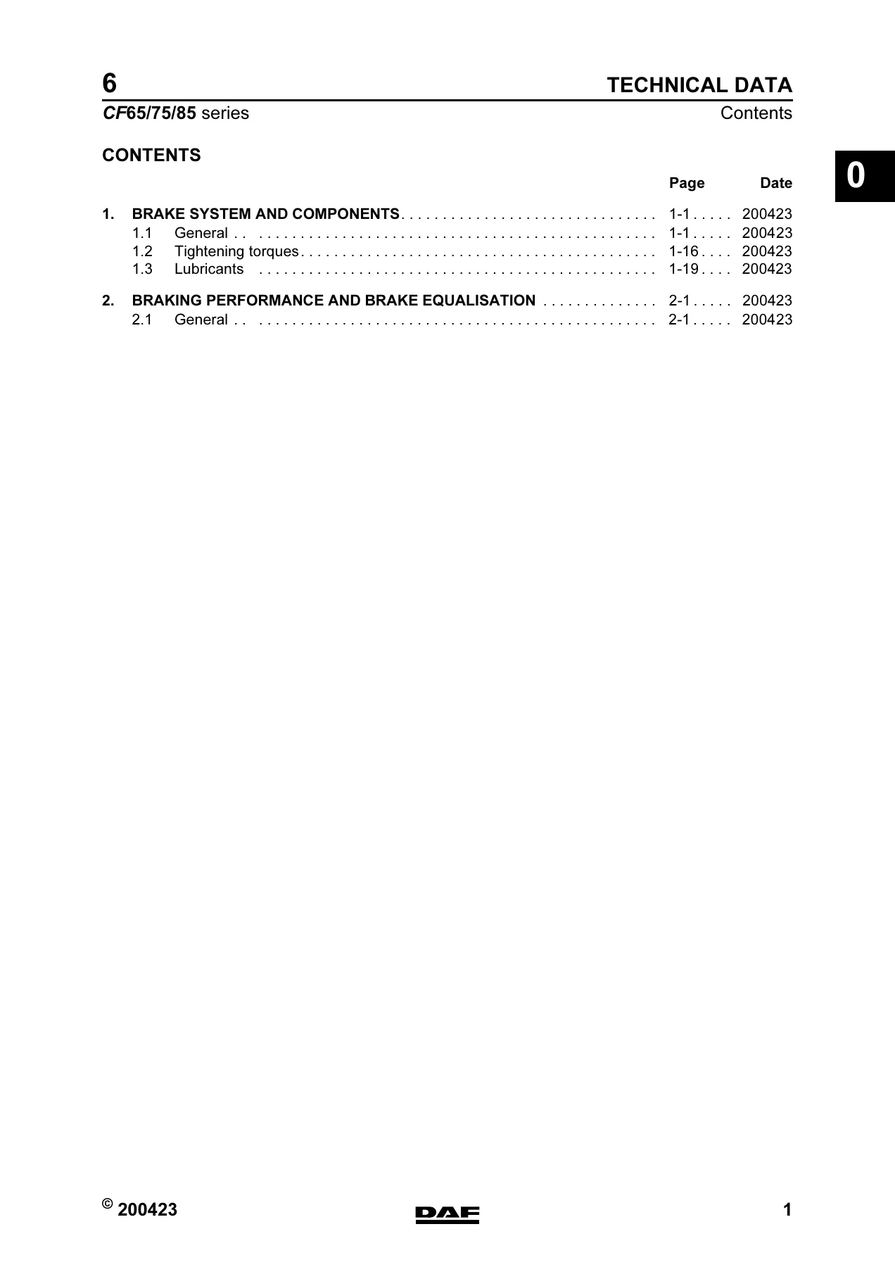
- Brake System and Components
- Braking Performance and Brake Equalisation
- Diagnostics — Disc Brake Construction and Drum Brake Construction
- Brake Diagrams for Fully Pneumatic Brake System
- EBS Brake System Brake Diagrams
- EBS-2 Brake System Brake Diagrams
- Operation of Brake Components
- Inspection and Adjustment
- Removal and Installation
- Disassembly and Assembly
Technical Data and Component Specifications
The technical data chapter opens with the coding system for components and connections used throughout the manual, then provides detailed specifications for every major brake component on the CF65, CF75 and CF85. Compressor data covers both the Knorr SWC 9057 single-cylinder water-cooled unit (255 cc) for the CF65 and the Wabco 911 504 two-cylinder water-cooled unit for the CF75 and CF85, including rejection dimensions for cylinder bore at the turning point of the first piston ring, piston ring groove heights for all three grooves, gudgeon pin hole diameter, gudgeon pin diameter, piston diameter, gudgeon pin bearing in connecting rod, and crankshaft bearing tolerances for both drive and non-drive sides.
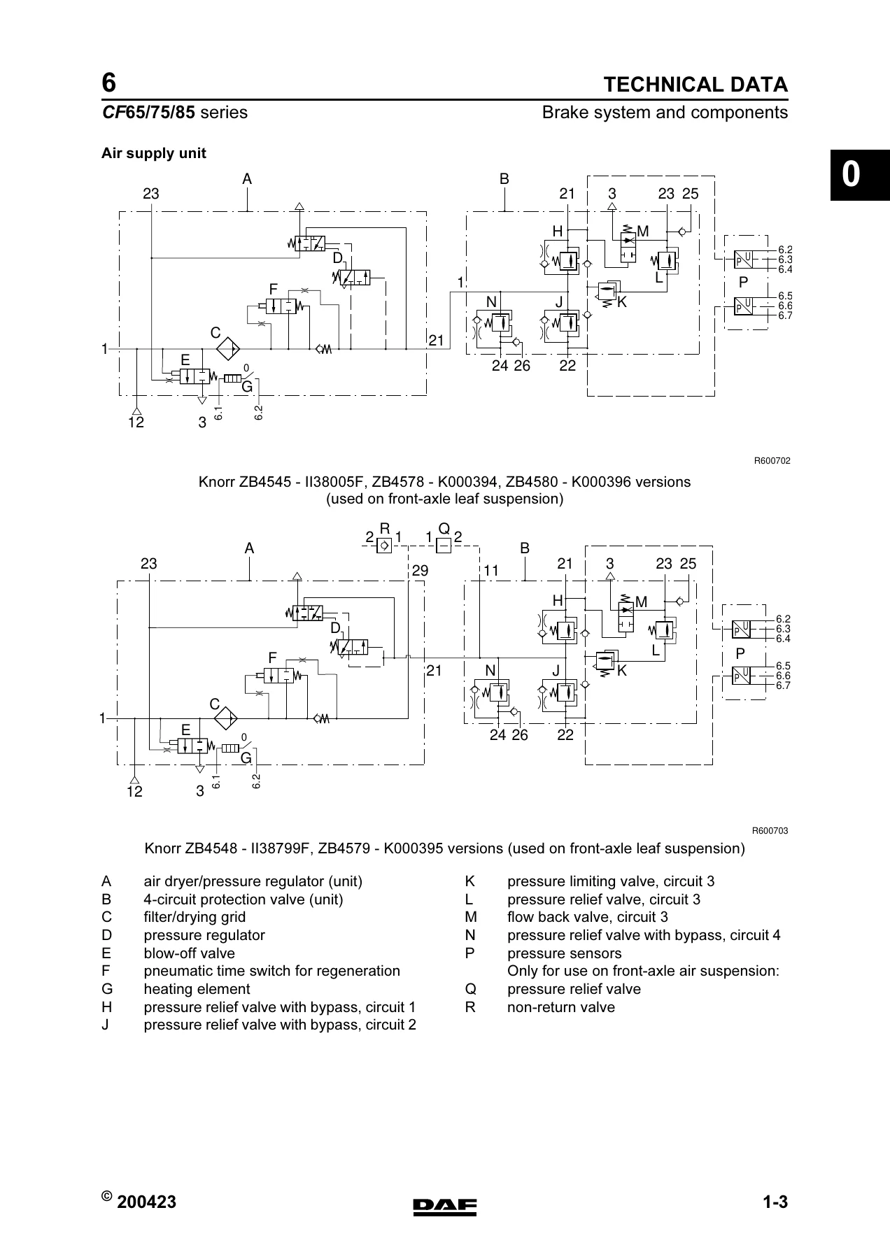
The air supply unit section provides supply pressures for all four circuits, opening pressures for circuits 1, 2 and 4, opening pressure for circuit 3, static closing pressure for all circuits, circuit 1 activation pressure for the flow-back function of circuit 3, cut-out and cut-in pressures for the pressure regulator, safety valve opening pressure, the heating element cut-in and cut-out temperatures, re-set time, and the pressure sensor voltage-to-pressure graph for circuits 1 and 2.
Foot brake valve specifications include the Knorr DX 61A pressure difference between circuits 1 and 2 and the actuation pressure differential, plus the characteristic curves. Load sensing valve characteristics are given for both leaf suspension and air suspension applications with their respective graphs. Brake light switch (Messmer 131 733) cut-in pressure, low-pressure switch cut-out pressures for both drum and disc brake designs, and the empty/load relay valve reduction ratios for Wabco 973 011 106 (1:1.5) and Wabco 973 011 107 (1:2.7) are documented. Relay valves are covered in parking brake (Knorr AC 577A) and service brake (Wabco 973 011 009 and 973 011 008) versions with their graphs.
The ABS valve magnet coil resistance (10–20 ohm at approximately 25°C) with electrical connection layout, ASR solenoid valve specifications with port and bleed identification, trailer control valve (Knorr AC 599A) with its advance adjustment procedure, safety valve opening pressure (Voss, approximately 16 bar), and the full specification of parking brake valves (Knorr DPM90DA with test position, DPM93D without test position, DPM90AA without test position with electrical switch, DPM92D without drawn vehicle connection) with their pressure-to-angle graphs are all covered.
Brake System and Components
This chapter is the component reference. It details the air supply unit with Knorr ZB4545-II38005F, ZB4578-K000394 and ZB4580-K000396 versions, plus the front-axle leaf suspension variants Knorr ZB4548-II38799F and ZB4579-K000395. Component identification diagrams show every valve, connection point and sensor in the air supply and four-circuit protection valve assembly. The chapter also covers brake linings for drum brakes including DAF 2100, DAF 3100 and Beral 156109N044 for the leading rear axle, brake pad specifications with maximum thickness and minimum lining thickness, brake caliper data, brake disc thickness specifications with rejection and turning dimensions, and brake drum dimensions including maximum reconditioning values and ovality limits.
Braking Performance and Brake Equalisation
This section covers EBS tyre classes and tyre size classification for the CF65, CF75 and CF85 range, explaining when tyre size changes require reprogramming of the EBS unit and when the EBS-2 system automatically recognises the change. Braking force graphs are provided for every tyre size used on these vehicles — 215/75 R17.5, 235/75 R17.5, 295/60 R22.5, 255/70 R22.5, 315/60 R22.5, 275/70 R22.5, 385/55 R22.5, 305/70 R22.5, 315/70 R22.5, 295/80 R22.5, 11 R22.5, 385/65 R22.5, 315/80 R22.5, 12 R22.5 and 13 R22.5 — with reference lines for different brake cylinder sizes and brake lever lengths.
The chapter includes the brake equalisation form for brake dynamometer testing, EC band graphs for laden tractor/semi-trailer and truck/trailer combinations, and the full procedure for checking and adjusting brake equalisation on EBS and non-EBS trucks with EBS and non-EBS trailers.
Diagnostics
Two fault-finding tables cover disc brakes and drum brakes separately. The disc brake table addresses symptoms including squealing or noise during braking, irregular brake pad wear, vehicle pulling to one side, poor braking deceleration, vibrations during braking, locking of the brakes, increased brake pad wear and dragging brakes. The drum brake table covers squealing, vehicle pulling to one side, poor braking deceleration, vibrations, locking of the brakes, increased brake lining wear, damaged brake drums, damaged brake linings and dragging brakes. Each entry lists possible causes and their remedies.
Brake Diagrams
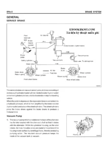
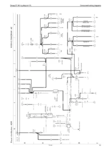
Three complete diagram sections are included: fully pneumatic brake system diagrams, EBS brake system diagrams and EBS-2 brake system diagrams. Each section has a legend identifying every component by number and description, plus vehicle-specific diagrams covering configurations from 4×2 FT through 6×2, 6×4, 8×2 and 8×4 with FT, FA, FAC, FAX, FAD and FTT variants, with and without trailer connections, with disc or drum brakes on the rear axle, leaf or air suspension, ABS with or without ASR, and spring brake cylinder arrangements on the front axle where applicable.
Operation of Brake Components
This section explains how each component works, with detailed cutaway diagrams and descriptions. Covered components include the compressor with its energy-saving function for CF75/CF85, safety valve, air supply unit (air dryer, pressure regulator, four-circuit safety valve), water blow-off valve, foot brake valve, relay valve, empty/load relay valve, brake light switch, load sensing valve for air suspension and leaf suspension, ABS valve with increasing, reducing and maintaining pressure functions, two-way valve, ASR solenoid valve, emergency filling and test connection, brake cylinder, parking brake valve with and without trailer connection and test position, low-pressure switch, spring brake cylinder including release tool procedures with uncrevable release bolt and control pin versions, trailer vehicle control valve with brake pressure advance adjustment and protection against breakage of service line, coupling head, automatic slack adjuster, disc brake for Knorr SB7000 and SN7000 variants with adjusting and wear indicator functions, and the VOSS 232 quick-release coupling.
Inspection and Adjustment
This is the practical chapter for service work. Procedures cover compressor capacity inspection, compressor line inspection, compressor control inspection, foot brake valve inspection and adjustment, load sensing valve inspection and adjustment for both air suspension and leaf suspension, empty/load relay valve inspection with empty and fully loaded testing, relay valve inspection, trailer vehicle control valve inspection, advance adjustment in trailer vehicle control valve, parking brake valve inspection for versions with and without trailer control, air supply unit input and output pressure checks, cut-out pressure adjustment, trailer vehicle system pressure adjustment, air dryer regeneration function check, four-circuit security valve check including pressure build-up on circuits 1, 2, 3 and 4 and circuit checks for leaks and flow-back function, automatic slack adjuster inspection for drum and disc brakes, brake drum inspection and reconditioning, drum lining inspection, brake pad inspection for Knorr SB7000 and SN7000, brake disc inspection, brake caliper play inspection, brake adjustment for drum and disc versions, and air tightness inspection.
Removal and Installation
Procedures cover quick-release coupling removal and installation, plug removal from and installation in socket, pipe removal and installation on pipe connectors, brake cylinder removal and installation for disc and drum applications, spring brake cylinder removal and installation for drum and disc brakes, automatic slack adjuster removal and installation, brake drum removal and installation, brake shoe removal and installation for 1354 and 1355T rear axles and for the 09N044 leading rear axle, brake lining installation on brake shoes with riveting procedure and joint checking, brake shoe bearing removal and installation, brake camshaft removal and installation, brake camshaft bearing removal and installation, brake back plate removal and installation for drum and disc brakes, compressor cylinder head gasket removal and installation, air dryer filter element removal and installation, brake pad removal and installation, brake disc removal and installation, Knorr SB7000 brake caliper removal and installation, Knorr SN7000 brake caliper removal and installation, brake caliper carrier removal and installation, bellows with brake caliper thrust piece removal and installation for both SB7000 and SN7000, bronze bearing bush removal and installation for both caliper types, rubber bearing bush removal and installation for both caliper types, and bellows of bronze bearing bush removal and installation for both caliper types.
Disassembly and Assembly
Detailed procedures cover disassembly and assembly of the brake chamber including diaphragm removal and installation, and disassembly and assembly of the Wabco spring brake cylinder including the spring brake section with the special tools required.
Tightening Torques and Lubricants
The tightening torque section lists specified torques for brake system components including safety valve attachment (72 Nm), brake caliper attachment bolts (285 Nm, always use new bolts with locking compound), pressure tool and guide bush bellows (180 Nm plus 90 degrees), rubber bearing bush pressure tool (440 Nm for SN7000), brake disc locking plate attachment bolts (8 Nm), brake cylinder attachment nuts (195 Nm), release bolt (45 Nm or 75 Nm for version with indication pin), spring brake cylinder fixing nuts (180–210 Nm), brake chamber clamping strap fixing bolts (34 Nm), release bolt for spring brake cylinder (25 Nm at minimum 5.1 bar), VOSS coupling socket (12 Nm), blow-off valve attachment (25 Nm), and compressor delivery valve attachment nuts and connecting rod bolts with angular displacement specifications.
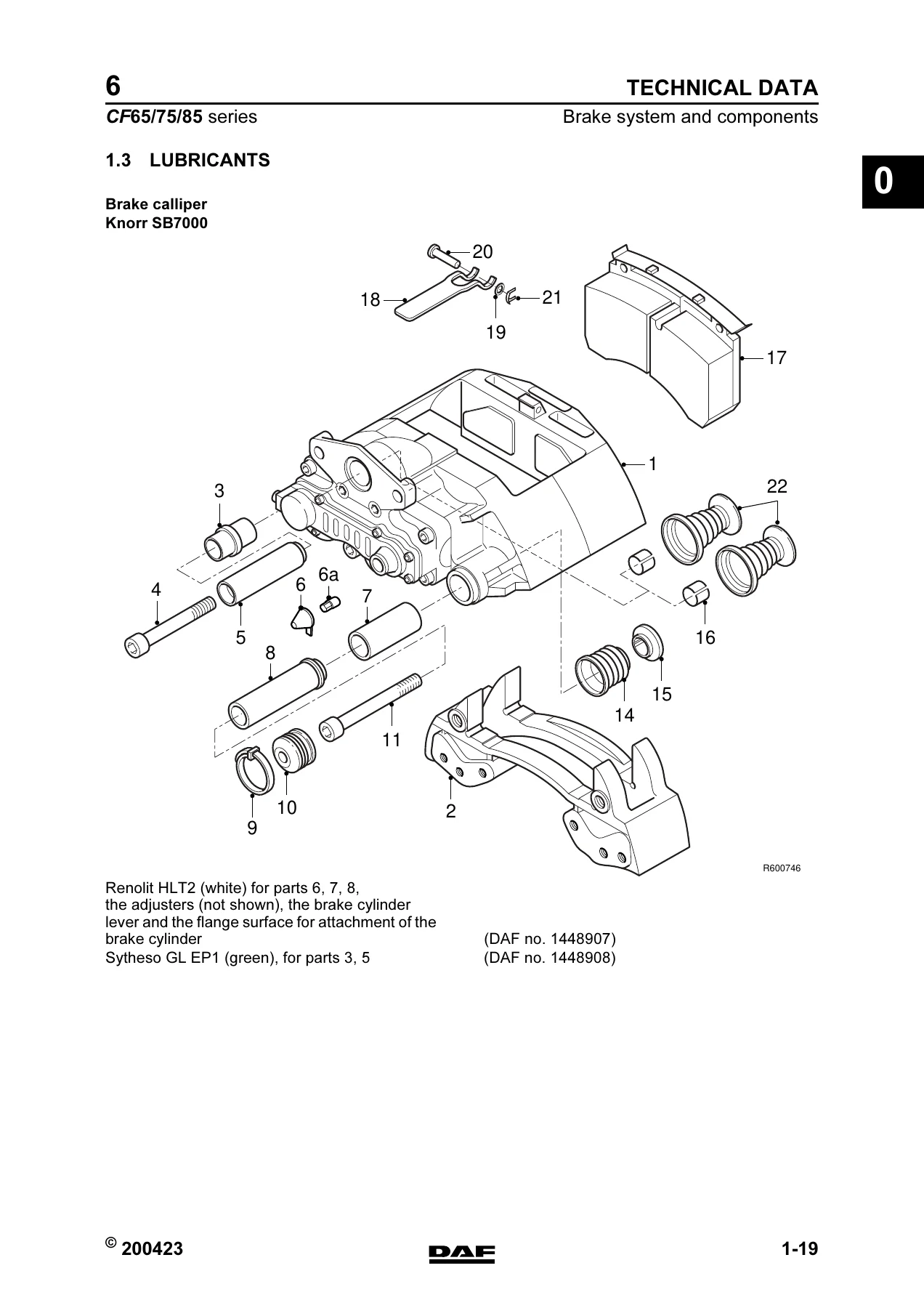
The lubricants section specifies Renolit HLT2 (white) for guide sleeves, adjusters, brake cylinder lever and flange surface for brake cylinder attachment, and Sytheso GL EP1 (green) for rubber bearing bushes, with DAF part numbers.
Who This Manual Is For
This DAF CF65, CF75 and CF85 braking system service manual is for fleet workshops, independent truck mechanics and owner-operators who maintain their own vehicles. The level of technical detail — from rejection dimensions on compressor components to the exact torque and angular displacement for cylinder head bolts — matches what you would expect from a manufacturer workshop manual.
Whether you are replacing brake pads, rebuilding a spring brake cylinder, diagnosing an ABS fault, adjusting load sensing valves or tracing a pneumatic circuit fault, this manual provides the procedures, specifications and diagrams you need. Everything is organised by system and component, with clear diagrams and specification tables. The fault-finding tables in the diagnostics section are particularly valuable for narrowing down braking problems before disassembly.
IMAGES PREVIEW
Instant PDF delivery. No shipping, no waiting. Download the manual immediately after payment and view it on any device — laptop, tablet or smartphone. Print the pages you need for the workshop. This is the complete document, not a sample or excerpt.
Reviews
There are no reviews yet.