
DAF LF CF XF105 Bodybuilder Guidelines 2007-51 Truck Upfit Manual PDF
Original price was: $44.95.$29.95Current price is: $29.95.
Complete DAF bodybuilder guidelines for LF45, LF55, CF65, CF75, CF85 and XF105 trucks. Covers chassis preparation, sub-frames, BAM attachment methods, PTOs, electrical connections, cab weights and superstructure installation. Update 2007-51, doc 200751, English PDF.
Description
DAF LF, CF & XF105 Bodybuilder Guidelines – 2007-51
This is the working reference DAF issues to bodybuilders and superstructure manufacturers who upfit its LF, CF and XF105 truck chassis. It is the document that tells you how far you can go with drilling, welding, sub-frame design, PTO selection, electrical tapping and cab loading before you need written approval from DAF. The update level is 2007-51, document number 200751, and the content covers the full range from the 7.5-tonne LF45 up to the XF105 tractor with MX engines.
Unlike a repair or workshop manual, this guideline set is structured around the interface between a DAF chassis and whatever the bodybuilder puts on it – a tipping body, tanker, refuse collector, crane, tail lift, demountable system, road sweeper, fire tender or fifth wheel. Every restriction, every permitted hole pattern and every permitted attachment method is spelled out so the finished vehicle keeps its structural integrity, warranty position and safe handling.
File Details
- Manual type: Bodybuilder Guidelines / Superstructure Installation Reference
- Brand: DAF
- Model series covered: LF45, LF55, CF65, CF75, CF85, XF105
- Language: English
- File format: PDF
- Document number: 200751
- Update / revision: 2007-51
- Page count: Approx. 326 pages
Chapters Covered
- 1. General
- 2. Chassis Information
- 3. General Information on Superstructures
- 4. Superstructures
- 5. Cab Information
- 6. Energy Consumers
- 7. Electrical System
- 8. Part Numbers
- 9. Reaction Form
Chapter 1 – General
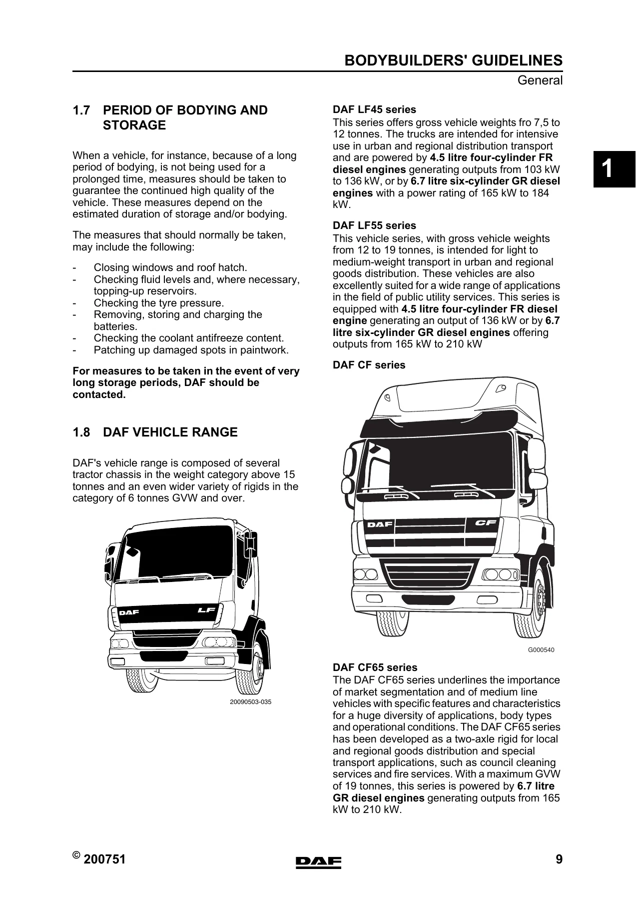
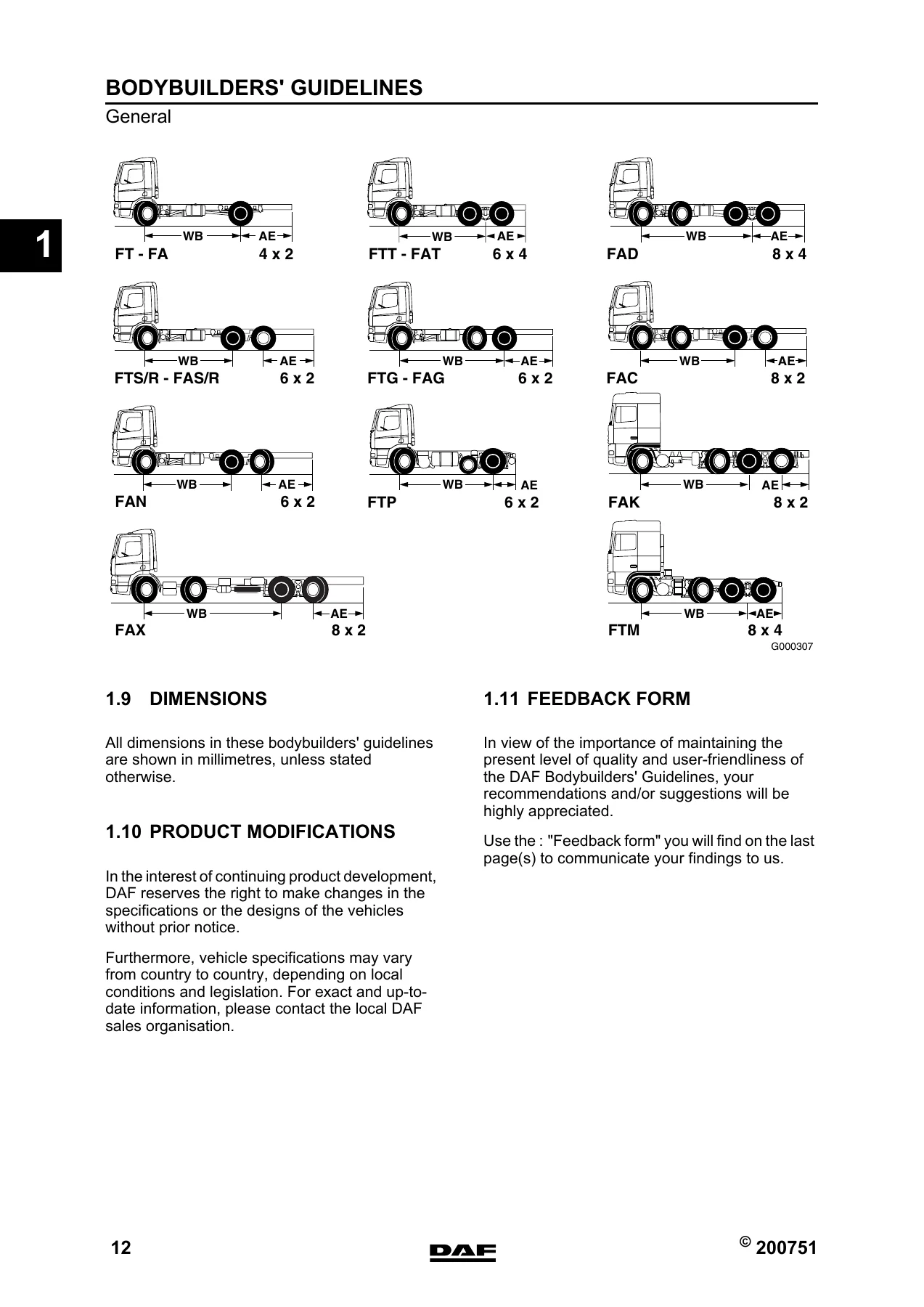
The opening chapter sets the rules of engagement. It covers the purpose of the guidelines, addresses to contact, why superstructure verification is required, statutory requirements, weight distribution tolerances, lateral stability, storage periods during bodying, the DAF vehicle range itself, dimension conventions and the product modification policy. The weight distribution section is the one to read first – it gives the minimum front axle percentage (20% solo or conventional trailer, 30% with a mid-axle trailer), the 25% driven axle rule for international traffic, the 2.5% left/right tolerance and the requirement to keep the combined centre of gravity inside the theoretical wheelbase.
Chapter 2 – Chassis Information
This is the mechanical heart of the guidelines. It opens with chassis levelling – three adjustable supports minimum, re-level after every move – then goes into hole drilling rules (never in the flanges, never in tapered tractor ends, 45° countersink both sides, minimum 70 mm from a bend, minimum edge distances). Welding on the chassis, cab and superstructure is covered with the exact isolation instructions: disconnect ECU connectors and battery terminals within 1 metre, never earth through engine, axles or springs.
Rear overhang modification is treated in detail – maximum 500 mm extension and 60% of wheelbase, retaining the rearmost cross member, 30 mm minimum behind rear spring or stabiliser brackets, 1200 mm maximum cross member spacing. The chapter also covers wheelbase modification (written permission required), attachment of components to the chassis with 10.9 flange bolts, replacing rivets with bolts or Huckbolts, air inlet and exhaust system clearances (70 mm from inlet openings, 50 mm around silencer and pipes), the fuel system with its three extra-tank connection methods, full chassis dimension tables, drawbar cross member data with D-value and V-value formulas, rear light brackets, wheel mounting torque tables, wheel clearance and mudguard location, EC-approved rear underrun protection and automatic lubrication.
Chapter 3 – General Information on Superstructures
Here you find the sub-frame construction rules (full length, no joints, tapered front end, 5 mm radius minimum, 1200 mm maximum cross member spacing, cross member height at least 0.6x side member height). It also introduces DAF’s BAM system – Body Attachment Methods 1 through 5 – with their three basic techniques (tie rods, consoles, attachment plates). Each BAM is described, illustrated and matched to superstructure types in a matrix. The first attachment point positions relative to the front axle centre line are listed for every chassis variant, including left-hand and right-hand side distances for leaf-sprung and air-sprung front axles. Detailed BAM drawings and attachment counts follow for FA LF45, FA LF55, FA LF55 18T, FA CF65, FA CF/XF, FAR/FAS CF and XF, FAG CF, FAN LF, FAN CF and XF, FAT CF and XF, FAC/FAX CF, FAD CF and XF, and FAK XF.
Chapter 4 – Superstructures
This is the application chapter. It covers fixed bodies with and without sub-frame, including the (high-)volume Low-Deck chassis and their minimum moment-of-inertia requirements, body-with-tail-lift sub-frame dimension tables up to 2000 kg capacity, vehicle loading crane attachment with capacity graphs for cranes behind the cab and at the rear overhang, tipper bodies including front-end ram, central ram, three-way and tipping demountable variants with sub-frame data and tipping pivot positions, tankers with sub-frame, fixed consoles, semi-flexible consoles, all-flexible consoles and three-point attachment on two-axle and multi-axle vehicles, concrete mixer and pump mounting with BAM 4, public utility vehicles including refuse collectors, rotating drum refuse collectors, road sweepers and gully emptiers, and finally fifth wheel mounting with base plate heights, bolt counts, KA dimension guidance and freedom-of-movement requirements.
Chapter 5 – Cab Information
Cab modification rules, maximum permissible additional cab weights per model and per location (roof, bunk, under-bunk, storage compartments), top sleeper mounting on LF and CF cabs, coil spring settings with the exact suspension heights for CF and XF, and the accessory mounting positions on LF, CF, CF Space Cab, XF Space Cab and XF Super Space Cab roofs. Roof spoiler setting procedure and setting ranges are also included.
Chapter 6 – Energy Consumers
Full ZF, Allison and Eaton gearbox ratios by model, PTO specification and selection rules, clutch-independent PTOs (front-end direct and indirect, crankshaft pulley, generator-driven, coolant pump, hydraulic pump, DAF engine PTO), clutch-dependent PTOs for every ZF gearbox with type, location, direction of rotation, gear ratio, speed factor, maximum torque and duration of operation, second PTO data, transfer box PTO, PTO operation and control, compressed air system tapping rules, tipper air-feed preparation and heating system connection requirements.
Chapter 7 – Electrical System
The largest chapter. Safety instructions, circuit diagram references, wiring marking system, earth connections, wire cross-section tables, assisted starting, battery charging, peak voltage protection, EMC compatibility, CAN SAE J1939 / ISO 11898 including FMS, CANopen, ISO 11992/2 and 11992/3, maximum additional load, additional batteries and alternators, connection points and locations for LF, CF and XF, dashboard switches and indication lights, engine speed control, accessory and cab connections, chassis connections, ESC control for LF, CF65, CF75/85 and XF, PTO control and protection for LF, CF and XF, trailer connection points, automated and automatic gearboxes, anti-theft, retarders, CAN Extension Box, Body Builders’ Module, CVSG gauges, Body Builders’ CAN J1939, tail lift preparation, axle load monitoring and refuse preparation.
Chapter 8 – Part Numbers
A compact parts list for the mounting hardware referenced throughout the guidelines: tie rods, attachment plates, mounting brackets, tanker consoles, chassis cross-connecting members, cab suspension springs, flange bolts and nuts by property class and length, electric connector housings and pins, bulkhead connectors for CF75-85 and XF, contour light cables, LF mudguard extension pieces, indication lamps, dashboard switches, CVSG gauges, air system adapters and miscellaneous parts including chassis section stock, fuel system couplings, converters, divider relays, PTO flanges and fifth wheel base plates.
Why This Bodybuilder Manual Matters
Getting a DAF chassis wrong at the upfit stage is expensive. Drill a hole in the wrong place on a side member flange and you have created a stress raiser that can crack under load. Weld without isolating the ECUs and you can destroy control units. Attach a tipper sub-frame outside the permitted moment of inertia and you risk the chassis flexing beyond what the body can tolerate. Select the wrong PTO and the gearbox oil temperature climbs past 110°C in continuous operation. Skip the weight distribution checks and the vehicle leans to one side, exceeds an axle rating, or handles unpredictably with a mid-axle trailer.
This guideline set exists precisely to prevent those outcomes. It gives you the exact bolt sizes, property classes, tightening torques, hole spacing, edge distances, sub-frame sections, attachment counts per BAM and per wheelbase, PTO torque limits and gear ratios, cut-in and cut-out conditions for PTO and ESC, connector pin-outs, wire numbers, CAN message layouts and FMS signal definitions. Whether you are building one tipper or running a body shop producing refuse collectors, tankers and crane trucks on DAF chassis every week, the answers are in here.
What You Can Do With It
The manual supports real work: preparing a chassis for bodying, planning a sub-frame, choosing the correct BAM for a given superstructure, laying out twist locks and tail lift attachment points, sizing a tipper sub-frame by wheelbase and rear overhang, mounting a loading crane with the correct sub-frame box section, wiring PTO controls through the BBM, tapping the compressed air system without exceeding the 70 l/min average consumption on CF75-85 and XF, connecting a tail lift via the VDHH 7-pole connector, setting the roof spoiler height for aerodynamic efficiency, positioning additional cab equipment within the permitted weight limits, and verifying that the finished vehicle still satisfies the statutory requirements in the country of registration.
IMAGES PREVIEW
Instant PDF Delivery
The file is delivered as a PDF download immediately after payment. No shipping, no waiting, no physical binder to lose. Print the sections you need for the workshop floor, or keep the whole document on a laptop, tablet or phone and search it while you are under the vehicle. The page layout matches the original DAF issue, so the drawings, tables and dimension callouts stay in their proper context.
Reviews
There are no reviews yet.