★ TRUSTED BY 321,897+ PROFESSIONALS WORLDWIDE
🏒
Trusted Business
Verified & Licensed
πŸ›‘οΈ
Virus Free Files
100% Safe Downloads
πŸ”’
Secure Payment
SSL Protected
⚑
Instant Delivery
Available Immediately
Sale!

Diamond DA20-A1 Aircraft Maintenance Manual Revision 15 (DA201 AMM) PDF Download

Original price was: $34.95.Current price is: $19.95.

Complete Diamond DA20-A1 Aircraft Maintenance Manual, Revision 15 (18 June 2012), document DA 201. Covers every ATA chapter from time limits and landing gear to the Rotax 912 engine, propeller, flight controls, electrical system and full wiring diagrams.

⚑
Instant PDF Download
Available immediately
πŸ’Ύ
Save to Your Device
Download & keep forever
πŸ›‘οΈ
Antivirus Scanned
100% virus-free
🌍
Trusted Worldwide
175,000+ customers

Description

Diamond DA20-A1 Aircraft Maintenance Manual Revision 15 – The Complete DA201 AMM

This is the full Diamond DA20-A1 Aircraft Maintenance Manual, Revision 15, issued as document DA 201 by Diamond Aircraft Industries Inc. of London, Ontario. The DA20-A1 AMM follows ATA Specification No. 100 and delivers the maintenance, troubleshooting, removal and installation, adjustment and inspection data needed to keep the DA20-A1 composite two-seat light aircraft in airworthy condition. Revision 15 carries the 18 June 2012 issue date and folds in the engineering changes, service bulletins and temporary revisions current at that time.

File Details

  • Manual type: Aircraft Maintenance Manual (AMM)
  • Manufacturer: Diamond Aircraft Industries Inc., London, Ontario, Canada
  • Aircraft model: DA20-A1
  • Document number: DA 201
  • Revision: Revision 15
  • Revision date: 18 June 2012
  • Language: English
  • File format: PDF
  • Page count: Approximately 605 pages
  • Layout standard: ATA Specification No. 100

Chapters Covered in This DA20-A1 Maintenance Manual

  • 01-00 Introduction
  • 02-00 Organization and Handling of the Manual
  • 03-00 General Description of the Aircraft
  • 04-00 Airworthiness Limitations (04-10 Life Limited Parts, 04-20 Paint Finish)
  • 05-00 Time Limits and Maintenance Checks (05-10 Time Limits, 05-20 Scheduled Maintenance Checks, 05-30 General Inspections, 05-40 Unscheduled Inspections)
  • 06-00 Dimensions and Areas
  • 07-00 Lifting and Shoring (07-10 Lifting, 07-20 Jacking)
  • 08-00 Leveling and Weighing
  • 09-00 Towing and Taxiing
  • 10-00 Parking and Mooring (10-10 Parking, 10-20 Mooring, 10-30 Parking Duration)
  • 11-00 Required Placards (11-10 Location of Placards)
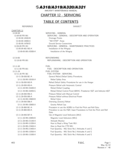
  • 12-00 Servicing (12-10 Replenishing, 12-20 Scheduled Servicing, 12-30 Unscheduled Servicing)
  • 20-00 Standard Practices – Airframe
  • 21-00 Environmental Systems (21-20 Distribution, 21-40 Heating)
  • 23-00 Communications (23-10 Speech Communication Bendix/King KX125)
  • 24-00 Electrical Power (24-30 DC Generation, 24-31 Battery System, 24-50 Electric Load Distribution)
  • 25-00 Equipment and Furnishings (25-10 Flight Compartment, 25-50 Baggage Compartment)
  • 27-00 Flight Controls (27-10 Aileron Control Systems, 27-11 Main Column, 27-20 Rudder Control Systems, 27-30 Elevator Control System, 27-40 Elevator Trim System, 27-50 Wing Flaps)
  • 28-00 Fuel (28-10 Storage Tank, 28-20 Distribution, 28-40 Indicating)
  • 31-00 Indicating and Recording Systems (31-10 Instrument Panel)
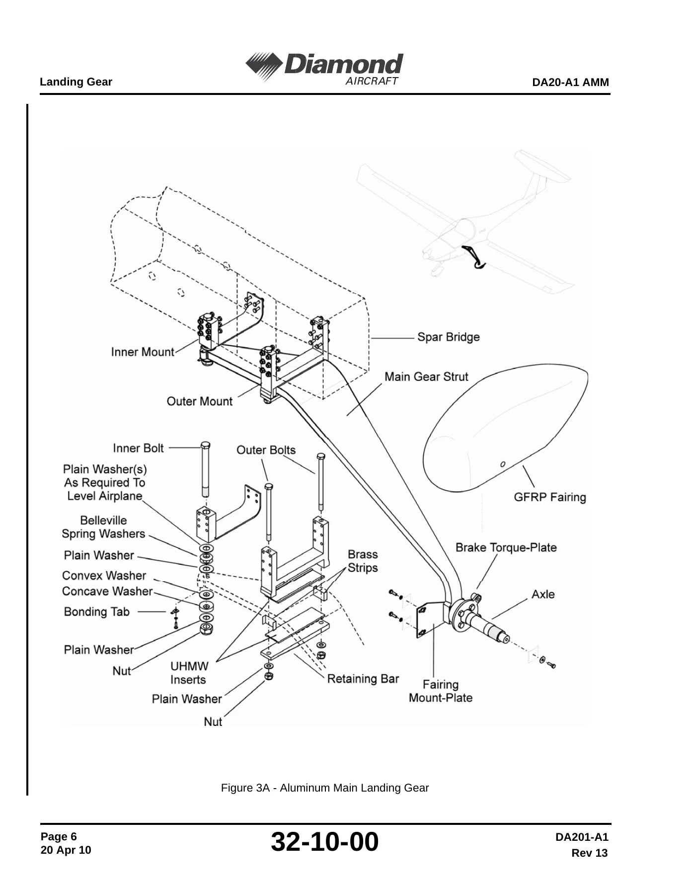
  • 32-00 Landing Gear (32-10 Main Landing Gear, 32-20 Nose Landing Gear, 32-40 Wheels and Brakes)
  • 33-00 Lights (33-10 Interior, 33-40 Exterior)
  • 34-00 Navigation and Pitot Static (34-10 Pitot Static, 34-12 Stall Warning System, 34-20 Attitude and Direction, 34-50 Position Determining Systems)
  • 51-00 Structures (51-10 Repair of Composite Parts, 51-20 Repair of Metal Parts)
  • 53-00 Fuselage (53-10 Main Frame, 53-11 Canopy, 53-31 Inspection Holes)
  • 55-00 Stabilizers (55-10 Horizontal Stabilizer, 55-20 Elevator, 55-30 Rudder)
  • 57-00 Wings (57-10 Wing Structure, 57-50 Wing Flaps, 57-60 Ailerons)
  • 61-00 Propeller
  • 71-00 Power Plant (71-10 Cowling, 71-20 Mounts, 71-60 Air Intakes and Guides)
  • 75-00 Engine Cooling
  • 76-00 Engine Controls
  • 77-00 Engine Indicating
  • 78-00 Exhaust
  • 79-00 Oil Systems (79-21 Oil Radiator, 79-30 Indicating)
  • 92-00 Wiring Diagrams (92-10 System Schematics, 92-30 Avionics Schematics)

Read as a whole, the DA201 AMM gives a technician a single controlled document for every task on the airplane. Each chapter is split into a description and function section, troubleshooting tables, then a maintenance block covering ground service, removal and installation, adjustment and test, checks and inspections, cleaning and painting, and repairs. Because the DA20-A1 is a fibreglass and carbon composite airframe with a Rotax 912 powerplant, the manual is deliberately explicit about the techniques that matter most on this aircraft – composite layup reference drawings, chamfer ratios for GFRP repairs, coin tap and light test inspection methods, delamination and disbond defect limits, and the specific torque values, service limits and lubrication intervals that keep the airframe and engine within their approved envelopes.

What This Diamond DA20-A1 AMM Lets You Do

  • Run the 50, 100, 200, 1000 and 6000 hour inspection checklists with the correct engine, propeller, cabin, structure, landing gear and general inspection steps.
  • Service the Rotax 912 engine – oil changes, oil filter replacement, compression tests, spark plug replacement, ignition circuit checks, carburetor heat checks and generator belt checks.
  • Remove and install the propeller, spinner and hub assembly using the published torque values and track tolerance.
  • Adjust, rig and safety the aileron, elevator, rudder, trim and flap control systems, including push rod eye-end setup and cable pre-tension.
  • Repair the composite airframe – GFRP laminate and sandwich repairs, delamination limits, fuselage layup reference, spar repair restrictions and painting.
  • Diagnose and fix the landing gear – main and nose gear removal, toe-in, camber and track adjustment, wheel bearings, brake bleeding and the parking brake valve.
  • Troubleshoot the electrical system, DC generation, battery system, load distribution, lighting, avionics and instrumentation using the Chapter 92 schematics.
  • Perform fuel system checks including the fuel shut off valve and check valve inspection.
  • Verify weight and balance, leveling, jacking, towing, mooring and placard requirements.

Why This Revision 15 AMM Matters

Component replacement times, torque values, composite defect limits and rigging tolerances on the DA20-A1 are not guesses. Revision 15 consolidates the latest engineering data, temporary revision TR 05-01 and the incorporated service bulletins – including DA20-32-05, DA20-79-03, DA20-79-08 and DA20-74-01 – so the maintenance you perform is the maintenance the manufacturer actually published. Getting the adjustment report values, cable tensions and control surface travels right is what prevents flutter, premature wear and airworthiness findings down the line.

Complete PDF Bookmark Tree

Complete Bookmarks

The complete bookmarks in the β€œDiamond DA20-A1 Aircraft Maintenance Manual Revision 15 (DA201 AMM) PDF Download” are as follows:

AIRCRAFT MAINTENANCE MANUAL – DA20-A1p. 1
FRONT MATTERp. 23
RECORD OF REVISIONSp. 3
HIGHLIGHTSp. 5
LIST OF TEMPORARY REVISIONSp. 7
LIST OF SERVICE BULLETINSp. 9
LIST OF EFFECTIVE PAGESp. 11
TABLE OF CONTENTSp. 23
CHAPTER 01-00 – INTRODUCTIONp. 27
Introductionp. 31
1. Generalp. 31
2. Revision Servicep. 31
3. Warning, Cautions and Notesp. 32
4. Manual Configurationp. 32
5. Contents (Peculiarities)p. 33
A. MAIN GROUP 01, GENERALp. 33
B. MAIN GROUP 02, EQUIPMENTp. 33
C. MAIN GROUP 03, AIRFRAMEp. 33
D. MAIN GROUP 04, PROPELLERp. 33
E. MAIN GROUP 05, ENGINEp. 33
6. Chaptersp. 33
7. Arrangement of Chaptersp. 34
A. STRUCTUREp. 34
B. CHAPTER CONTENTSp. 34
8. Order of Pagesp. 35
A. PAGES PRECEDING THE ACTUAL MANUALp. 35
9. Illustrationsp. 35
CHAPTER 02-00 – ORGANIZATION AND HANDLING OF THE MANUALp. 37
Organization and Handling of the Manualp. 41
1. Generalp. 41
2. Validityp. 41
3. Revisionsp. 41
4. Temporary Revisionsp. 41
5. Record of Revisionsp. 42
6. Check Listp. 42
7. Service Bulletinsp. 42
A. Alert Service Bulletinsp. 42
B. Service Bulletinsp. 42
8. List of Applicable Publicationsp. 42
9. Abbreviationsp. 43
CHAPTER 03-00 – GENERAL DESCRIPTION OF THE AIRCRAFTp. 45
General Description of the Aircraftp. 49
1. Generalp. 49
2. Descriptionp. 49
3. Vendor Documentationp. 54
CHAPTER 04-00 – AIRWORTHINESS LIMITATIONSp. 57
Airworthiness Limitationsp. 61
1. Generalp. 63
04-10 – Limited Time Partsp. 65
1. Generalp. 65
04-20 – Paint Finishp. 67
1. Generalp. 67
CHAPTER 05-00 – TIME LIMITS AND MAINTENANCE CHECKSp. 69
Time Limits and Maintenance Checksp. 73
1. Generalp. 73
05-10 – Time Limitsp. 75
1. Time Limits for Equipmentp. 75
05-20 – Scheduled Maintenance Checksp. 77
Maintenance Practicesp. 78
1. Generalp. 77
2. 50, 100, 200, and 1000 hour Inspection Checklistp. 77
Inspection Checklist DA20-A1p. 78
1. Generalp. 78
2. Initial Test Runp. 78
3. Engine:p. 79
4. Propellerp. 83
5. Cabinp. 84
6. Structure and Control Surfacesp. 85
7. Landing Gearp. 88
8. Generalp. 89
9. Maintenance Reportp. 90
10. Maintenance Check Flight Reportp. 91
11. 6000 Hour Inspectionp. 93
A. Types of Inspectionp. 93
B. Defect Limits for Compositesp. 94
6000 HOUR INSPECTION CHECKLIST DA20-A1 KATANAp. 95
05-30 – General Inspectionsp. 107
1. Generalp. 107
2. Pre-Flight Inspectionp. 107
3. Post-Flight Inspectionp. 107
4. Fuel Shut off Valve and Check Valve Inspectionp. 107
(1) Turn fuel shut off valve to CLOSED position.p. 107
(2) Ensure throttle lever is fully in Idle position.p. 107
(3) Turn ignition switch ON, fuel pressure warning light should be illuminated. If not illuminated, crank engine until fuel pressure warning light illuminates.p. 107
(4) To check that the fuel shut off valve is operating properly, switch electric fuel pump ON, fuel pressure warning light should remain illuminated.p. 108
(5) Turn fuel shut off valve to OPEN position, fuel pressure warning light should turn OFF.p. 108
(6) Visually verify, through the filler neck, that fuel is flowing through the return line into the fuel tank.p. 108
(7) To ensure check valve is operating properly, switch electric fuel pump OFF, fuel pressure warning light should not illuminate for at least one minute, visually verify no fuel is returning to the fuel tank.p. 108
05-40 – Unscheduled Inspectionsp. 109
1. Generalp. 109
2. Special Inspectionsp. 109
A. Hard Landingp. 109
(1) The landing gear fittings should be inspected, using a mirror and flashlight, for defects (e.g. cracks), inspect surrounding structure for delamination.p. 109
(2) Condition of the complete nose gear assembly must be checked (cracks, deformation). Special attention must be given to the upper cross bar of the engine mount to which the nose wheel assembly is attached. Check for deformation.p. 109
(3) The top hat profile in the fuselage bottom should be inspected for white spots and delamination in the area around the bearings for the nose gear assembly.p. 109
(4) Check the nose gear assembly in the unloaded condition for excessive play in the bearings due to overloading.p. 109
(5) In addition to the landing gear, all control surfaces (hinges, balancing weights), and the complete engine mounting (engine mount, mounting points to the firewall, shock mounts, etc.) should be inspected.p. 109
B. Sudden Engine Stoppage (Prop Strike)p. 110
C. Non-Operation of more than 30 Daysp. 110
D. Replacement of Engine, Ignition, or Instrumentsp. 110
E. Tail Impact Damage Inspectionp. 110
(1) Remove the rudder. Reference chapter 27-20-30.p. 110
(2) Examine the areas highlighted in figure 1 for cracking, delamination, dis-bonding or any other damage. Reference figure 1.p. 110
(3) If damage is found to any of the structures contact the manufacturer for repair instructions.p. 110
(4) If there is no damage, the aircraft may be re-assembled.p. 110
CHAPTER 06-00 – DIMENSIONS AND AREASp. 113
Dimensions and Areasp. 117
1. Generalp. 117
A. Unit Conversionsp. 117
2. Dimensionsp. 117
3. Adjustment Values for Control Surfaces and Trimp. 118
4. Control Surface Gapsp. 121
5. Weight And Static Moments Of Control Surfacesp. 121
CHAPTER 07-00 – LIFTING AND SHORINGp. 123
Lifting and Shoringp. 127
1. Generalp. 127
2. Required Equipmentp. 127
07-10 – Liftingp. 129
1. Generalp. 129
07-20 – Jackingp. 131
1. Generalp. 131
2. Jacking the Airplanep. 131
3. Lowering the Airplanep. 131
CHAPTER 08-00 – LEVELING AND WEIGHINGp. 133
Leveling and Weighingp. 137
1. Generalp. 137
2. Levelingp. 137
3. Weighingp. 137
4. Permissible Empty Weight C.G. Rangep. 139
CHAPTER 09-00 – TOWING AND TAXIINGp. 141
Towing and Taxiingp. 145
1. Generalp. 145
2. Equipment and Accessoriesp. 145
09-10 – Towingp. 147
1. Generalp. 147
2. Towing Procedurep. 147
A. Towing without tow vehiclep. 147
B. Towing with a tow vehiclep. 147
C. Moving without Tow Barp. 148
09-20 – Taxiingp. 149
1. Generalp. 149
2. Taxiing Procedurep. 149
A. Remove all foreign object from the airplane area (tools, tool carts, etc.).p. 149
B. Remove chocks, mooring ropes, and tow bar if required.p. 149
C. Set parking brake by pulling the parking brake lever and operating the toe brakes.p. 149
D. Start engine (see Flight Manual DA 20 KATANA)p. 149
E. Release parking brake.p. 149
F. Check brake operation during taxiing.p. 149
G. Taxi the airplane to the desired position.p. 149
H. Turn off engine (see Flight Manual DA 20 KATANA).p. 149
I. Park the airplane and moor as required (see Chapter 10).p. 149
CHAPTER 10-00 – PARKING AND MOORINGp. 151
Parking, Mooring, Storage and Return to Servicep. 155
1. Generalp. 155
2. Equipment and Accessoriesp. 155
10-10 – Parkingp. 157
1. Generalp. 157
2. Short Term Parkingp. 157
A. Flight Control Lock Removal and Installationp. 157
3. Long Term Parkingp. 158
10-20 – Mooringp. 159
1. Generalp. 159
2. Mooringp. 159
10-30 – Parking Durationp. 161
1. Parking Over 30 Daysp. 161
A. Engine Preservation and De Preservationp. 161
B. Fuel Supplyp. 161
C. Landing Gear, Wheels and Tiresp. 161
D. Electrical Systemp. 161
E. Lubricationp. 161
F. Instrumentsp. 161
G. Loose Equipmentp. 162
H. Electronic Equipmentp. 162
I. Airplane Ventilationp. 162
J. Parking and Mooringp. 162
CHAPTER 11-00 – REQUIRED PLACARDSp. 163
Required Placardsp. 167
1. Generalp. 167
2. Materialsp. 167
3. Removal and Installationp. 167
11-10 – Location of Placardsp. 169
1. Generalp. 169
CHAPTER 12-00 – SERVICINGp. 177
Servicingp. 181
1. Generalp. 181
12-10 – Replenishingp. 183
1. Fuel Systemp. 183
A. Refuelingp. 183
B. Defuelingp. 183
2. Oil Systemp. 183
3. Brake Systemp. 185
4. Tiresp. 185
5. Batteryp. 186
6. Cooling Systemp. 186
A. Adding Coolantp. 186
12-20 – Scheduled Servicingp. 189
1. Fuel Systemp. 189
2. Lubrication Schedulep. 189
12-30 – Unscheduled Servicingp. 195
1. Cleaning, Exteriorp. 195
2. Cleaning Interiorp. 195
3. Engine Cleaningp. 195
4. Snow and Ice Removalp. 196
CHAPTER 20-00 – STANDARD PRACTICES – AIR FRAMEp. 197
Standard Practices – Airframep. 201
1. Generalp. 201
2. Bolt and Nut Types Used in the Aircraftp. 201
3. Standrad Torquesp. 201
A. AN Fine Thread Seriesp. 202
B. AN Coarse Thread Seriesp. 202
C. DIN Specificationsp. 202
4. Special Torquesp. 203
5. Measuring Torque Detailsp. 204
CHAPTER 21-00 – ENVIRONMENTAL SYSTEMSp. 205
Environmental Systemsp. 209
1. Generalp. 209
21-20 – Distributionp. 211
1. Functional Decriptionp. 211
A. Heating System and Canopy Defroster (Refer to Figure 1)p. 211
B. Ventilationp. 211
2. Maintenance Informationp. 211
A. Inspectionsp. 211
100 hour inspectionp. 211
200 hour inspectionp. 211
21-40 – Heatingp. 213
1. Heat Exchanger Removalp. 213
2. Heat Exchanger Inspectionp. 213
CHAPTER 23-00 – COMMUNICATIONSp. 215
Communicationsp. 219
1. Generalp. 219
23-10 – Speech Communication Bendix/King KX125p. 221
1. Generalp. 221
2. System Descriptionp. 222
A. Receiver Descriptionp. 222
B. Transmitter Descriptionp. 222
C. Unit Operationp. 222
3. Troubleshootingp. 224
4. Maintenance Informationp. 225
A. Generalp. 225
B. Removal and Installation of the Radio Unitp. 225
CHAPTER 24-00 – ELECTRICAL POWERp. 227
Electrical Powerp. 231
1. Generalp. 231
2. Descriptionp. 233
A. Batteryp. 233
B. Battery Relayp. 233
C. Master Switch (Split Switch)p. 233
D. Starting Relayp. 234
E. Generator Warning Lightp. 234
F. Ammeterp. 234
G. Voltmeterp. 234
H. Electrical Barsp. 234
I. Avinoics Master Switch and Avionics Busp. 234
3. Troubleshootingp. 234
4. Maintenance Informationp. 235
24-30 – DC Generationp. 237
1. Generalp. 237
2. Descriptionp. 239
3. Troubleshootingp. 240
4. Removal Installationp. 240
A. Generatorp. 240
B. Overvoltage Control Relayp. 242
C. Overvoltage Sensorp. 242
5. Maintenance Informationp. 242
24-31 – Battery Systemp. 243
1. Generalp. 243
2. Descriptionp. 243
3. Troubleshootingp. 243
4. Maintenance Informationp. 244
5. Removal and Installationp. 245
A. Batteryp. 245
B. Master Relayp. 245
C. Ammeterp. 246
D. Master Switch (Split Switch)p. 246
6. Cleaningp. 247
24-50 – Electric Load Distributionp. 249
1. Generalp. 249
2. Descriptionp. 251
3. Troubleshootingp. 251
4. Maintenance Informationp. 251
5. Removal and Installationp. 252
A. Circuit Breakersp. 252
CHAPTER 25-00 – EQUIPMENT/FURNISHINGSp. 253
Equipment/Furnishingp. 257
1. Generalp. 257
25-10 – Flight Compartmentp. 259
1. Functional Descriptionp. 259
A. Map Packetsp. 259
B. Fire Extinguisherp. 259
C. Emergency Locator Transmitterp. 259
D. Lining of Side Panelsp. 260
E. Instrument Panel Coverp. 260
F. Center Console Coverp. 260
G. Seatsp. 260
H. Safety Beltsp. 260
2. Removal and Installationp. 261
A. ELTp. 261
B. Instrument Panel Coverp. 261
C. Seat Shellsp. 261
D. Seat Beltsp. 262
E. Center Console Coverp. 262
3. Cleaningp. 262
A. Seatsp. 262
B. Safety Beltsp. 262
25-50 – Baggage Compartmentp. 263
1. Generalp. 263
CHAPTER 27-00 – FLIGHT CONTROLSp. 265
Flight Controlsp. 269
1. Generalp. 269
2. Descriptionp. 269
3. Troubleshootingp. 269
4. Maintenance and Inspection Informationp. 269
100 hour inspectionp. 269
27-10 – Ailerons Control Systemsp. 271
1. Generalp. 271
2. Descriptionp. 271
3. Troubleshootingp. 272
4. Removal and Installationp. 272
A. Control Sticksp. 272
B. Aileraon Push Rods Connected to Control Sticksp. 273
C. Bellcrank Attached to the Forward Control Bulkheadp. 273
D. Push Rod in Center Consolep. 273
E. Bellcrank attached to the Aft Control Push Rodsp. 274
F. Push Rod in Wingp. 274
G. Aileron Bellcrank in Wingp. 274
H. Aileronp. 275
5. Adjustmentp. 277
27-11 – Main Columnp. 279
1. Generalp. 279
2. Descriptionp. 279
3. Troubleshootingp. 279
4. Removal and Installationp. 279
A. Control Sticksp. 279
B. Elevator Torque Tube Assemblyp. 279
5. Adjustmentp. 280
A. Control Sticksp. 280
27-20 – Rudder Control Systemp. 281
1. Generalp. 281
2. Descriptionp. 281
3. Troubleshootingp. 284
27-20-10 – Rudder Pedal Assemblyp. 285
1. Generalp. 285
2. Descriptionp. 285
3. Removal and Installationp. 286
A. Pedal Assemblyp. 286
27-20-20 – Rudder Controls in Fuselagep. 287
1. Generalp. 287
2. Descriptionp. 287
3. Removal and Installationp. 287
A. Cables between the Firewall and the Rudder Leverp. 287
B. Cables between the Rudder Lever and the Rudder Lower Mounting Platep. 287
4. Adjustmentp. 288
27-20-30 – Rudderp. 289
1. Generalp. 289
2. Descriptionp. 289
3. Removal and Installationp. 289
4. Adjustmentp. 289
A. Rudder Deflectionp. 289
27-30 – Elevator Control Systemp. 291
1. Generalp. 291
2. Descriptionp. 291
3. Troubleshootingp. 292
4. Removal and Installationp. 292
A. Items (1) and (2): Control Sticks and Torque Tube Assemblyp. 292
B. Item (3): Elevator Push Rod in Control Consolep. 292
C. Item (4): Elevator Push Rod in Fuselage Tubep. 292
D. Item (6): Elevator Push Rod in Vertical Stabilizerp. 293
E. Elevatorp. 295
5. Adjustmentp. 297
A. Items (1) + (2): Control Sticks and Torque Tube Assemblyp. 297
B. Item (3) + (4): Push Rods in Control Console and Fuselage Tubep. 297
C. Item (6): Push Rod in Vertical Stabilizerp. 297
D. Elevator Stopsp. 298
27-40 – Elevator Trim Systemp. 299
1. Generalp. 299
2. Descriptionp. 299
3. Troubleshootingp. 300
4. Removal and Installationp. 301
A. Rocker Switchp. 301
B. Actuating Motor (Refer to Figure 7, Item 2)p. 301
C. Spring Mount Assembly (Refer to Figure 7, Item 2)p. 302
D. Anti-Servo Tab Assemblyp. 302
5. Adjustmentp. 303
27-50 – Wing – Flapsp. 305
1. Generalp. 305
2. Descriptionp. 305
3. Troubleshootingp. 306
4. Removal and Installationp. 307
A. Wing Flapsp. 307
B. Bellcrank in Fuselagep. 309
C. Bellcrank in Wingp. 309
D. Push-Rodp. 310
E. Flap Actuatorp. 310
F. Current Limiterp. 312
5. Adjustmentp. 314
CHAPTER 28-00 – FUELp. 317
Fuelp. 321
1. Generalp. 321
2. Descriptionp. 321
A. Fuel System Description (S/N 10002 through S/N 10092) (Refer to Fig 1)p. 321
B. Fuel System Description (S/N 10093 and subsequent) (Refer to Fig 2)p. 321
3. Fuel Shut Off Valve And Check Valve Inspection
28-10 – Storage (Tank)p. 325
1. Generalp. 325
2. Descriptionp. 325
3. Troubleshootingp. 325
4. Removal and Installation of the Fuel Tankp. 326
A. Removalp. 326
B. Installationp. 326
5. Leakage Testp. 326
6. Repairp. 326
28-20 – Distributionp. 327
1. Generalp. 327
2. System Descriptionp. 327
A. Fuel Shut Off Valvep. 327
B. Electrical Fuel Pumpp. 327
C. Mechanical Fuel Pumpp. 328
3. Troubleshootingp. 328
4. Removal and Installationp. 329
A. Fuel Shut-Off Valvep. 329
B. Electrical Fuel Pumpp. 329
C. Maintenance of the Filter Elementp. 329
D. Mechanical Fuel Pumpp. 330
28-40 – Indicatingp. 331
1. Generalp. 331
2. System Descriptionp. 331
A. Fuel Quantity Indicating Systemp. 331
B. Fuel Pressure Sensorp. 331
3. Troubleshootingp. 331
4. Removal and Installationp. 332
A. Fuel Pressure Sensorp. 332
B. Fuel Quantity Sensorp. 332
5. Calibrationp. 333
A. Fuel Quantity indicator Adjustmentp. 333
CHAPTER 31-00 – INDICATING/RECORDING SYSTEMSp. 335
Indicating/Recording Systemsp. 339
1. Generalp. 339
31-10 – Instrument Panelp. 341
1. Generalp. 341
2. Descriptionp. 341
3. Removal and Installationp. 344
A. Removalp. 344
B. Installationp. 344
CHAPTER 32-00 – LANDING GEARp. 345
Landing Gearp. 349
1. Generalp. 349
2. Troubleshootingp. 349
3. Maintenance Informationp. 349
32-10 – Main Landing Gearp. 351
1. Generalp. 351
2. Descriptionp. 351
3. Troubleshootingp. 351
4. Removal and Installationp. 352
A. Main Landing Gearp. 352
5. Adjustmentp. 354
A. Play in Wheel Bearingp. 354
B. Toe in, Camber, and Trackp. 354
Main Landing Gearp. 355
1. Generalp. 355
2. Descriptionp. 355
3. Troubleshootingp. 357
4. Removal and Installationp. 357
A. Generalp. 357
B. Removalp. 357
C. Installationp. 358
5. Adjustmentp. 359
A. Equipmentp. 359
B. Procedurep. 359
32-20 – Nose Landing Gearp. 361
1. Generalp. 361
2. Descriptionp. 361
3. Removal and Installationp. 363
A. Nose Landing Gear Strutp. 363
B. Nose landing Gear Fork Assemblyp. 366
C. Shock Absorber Assemblyp. 367
D. Shock Absorber Assembly Elementsp. 369
4. Adjustmentp. 374
A. Nose Wheel Steering Frictionp. 374
B. Nose Wheel Balancing
C. Nose Landing Gear Leg Lateral Free Play
32-40 – Wheels and Brakesp. 375
1. Generalp. 375
2. Descriptionp. 375
3. Troubleshootingp. 377
4. Removal and Installationp. 377
A. Main Wheelsp. 377
B. Nose Wheelp. 379
C. Brake Master Cylinderp. 380
D. Caliperp. 381
E. Disc Brakep. 382
F. Brake Liningsp. 382
G. Parking Brake Valvep. 383
H. Parking Brake Valvep. 384
I. Remove the Parking Brake Valve.p. 384
J. Install the Parking Brake Valvep. 384
5. Bleeding of Brake Systemp. 387
6. Adjustmentp. 388
CHAPTER 33-00 – LIGHTSp. 389
33-10 – Interiorp. 393
1. Generalp. 393
2. Descriptionp. 393
3. Troubleshootingp. 393
4. Removal and Installationp. 394
A. Lighting Modulep. 394
33-40 – Exteriorp. 397
1. Generalp. 397
2. Descriptionp. 397
3. Troubleshootingp. 397
4. Removal and Installationp. 399
A. Position Light Bulbp. 399
B. ACL bulbp. 399
C. ACL Power Supplyp. 400
D. Navigation lightp. 400
E. Taxiing Lightp. 400
CHAPTER 34-00 – NAVIGATION AND PITOT STATICp. 401
Navigation and Pitot Staticp. 405
1. Generalp. 405
34-10 – Pitot Staticp. 407
1. Generalp. 407
2. Descriptionp. 408
A. Pitot Head/Linesp. 408
B. Drain Systemp. 408
C. Altimeterp. 409
D. Airspeed Indicatorp. 409
E. Vertical Speed Indicatorp. 410
F. Outside Air Temperature Indicatorp. 410
3. Troubleshootingp. 410
4. Maintenance Informationp. 411
5. Removal and Installationp. 411
A. Pitot headp. 411
B. Instrumentsp. 411
C. Pitot Static Testp. 412
D. Airspeed Indicatorp. 412
E. Altimeterp. 412
F. Safety Precautions during the Testp. 412
34-12 – Stall Warning Systemp. 413
1. Descriptionp. 413
34-20-00 – Attitude and Directionp. 415
1. Generalp. 415
2. Descriptionp. 415
A. Magnetic Compassp. 415
B. Turn and Slip Indicatorp. 415
C. Directional Gyrop. 415
D. Attitude Gyrop. 416
3. Troubleshootingp. 416
4. Removal and Installationp. 417
A. Magnetic Compassp. 417
B. Turn and Slip Indicator, Directional Gyro, Attitude Gyrop. 417
5. Compass Compensationp. 417
34-50-00 – Position Determining Systemsp. 419
1. Generalp. 419
CHAPTER 51-00 – STRUCTURESp. 421
Standard Practices and Structuresp. 425
1. Generalp. 425
2. Identification of Primary Structurep. 425
3. Inspection Techniquesp. 426
A. Examine Visuallyp. 426
B. Light Testp. 426
C. Coin Tap Testp. 427
51-10 – Repair of Composite Partsp. 429
1. Approved Material, Suppliersp. 429
A. Resin and Hardnerp. 429
B. Glass Fiber Clothp. 429
C. Carbon Fiber Clothp. 429
2. Damage Classificationsp. 431
3. Defect Limits for Compositesp. 432
A. Cracks:p. 432
B. Surface scratchesp. 432
C. Delamination and disbond from core:p. 432
D. Surface Dents:p. 433
4. Fuselage Layupp. 433
5. GFRP Repairp. 440
6. Sandwich Repairp. 441
A. Minor Surface Damagep. 441
B. Damage to the Entire Sandwichp. 441
7. Laminate Repairp. 442
A. Minor Damagep. 442
B. Major Damagep. 443
8. Spar Repairp. 444
9. Paintingp. 444
51-20-00 – Repair of Metal Partsp. 445
1. Generalp. 445
A. Steel Fittingsp. 445
CHAPTER 53-00 – FUSELAGEp. 447
Fuselagep. 451
1. Generalp. 451
53-10-00 – Main Framep. 453
1. Generalp. 453
2. Bulkheads And Stiffenersp. 453
A. Firewallp. 453
B. Floor Elementp. 453
C. Top Hat Profilep. 453
D. Forward Control Bulkheadp. 453
E. Spar Bridgep. 454
F. Aft Control Bulkheadp. 454
G. B-Bulkheadp. 454
H. Vertical Bulkheadp. 454
I. Lower Tailfin Bulkheadp. 454
J. Tailfin Web and Lower Tailfin Ribp. 454
K. Anti Flutter Bracketp. 454
3. Paint Application Procedure for the Aircraft Belly and the Cowlingsp. 455
A. High Temperature Paint Repair of Aircraft Belly and Cowlingsp. 455
53-11-00 – Canopyp. 459
1. Generalp. 459
2. Troubleshootingp. 460
3. Maintenance Informationp. 460
4. Removal and Installationp. 461
A. Canopy, Completep. 461
B. Emergency Windowsp. 461
53-31-00 – Inspection Holesp. 463
1. Generalp. 463
2. Descriptionp. 463
CHAPTER 55-00 – STABILIZERSp. 465
Stabilizersp. 469
1. Generalp. 469
55-10 – Horizontal Stabilizerp. 471
1. Generalp. 471
2. Descriptionp. 471
3. Removal and Installationp. 471
A. Horizontal Stabilizerp. 471
55-20-00 – Elevatorp. 473
1. Generalp. 473
2. Descriptionp. 473
3. Remove/Install the Elevatorp. 473
A. Remove the Elevatorp. 473
B. Install the Elevatorp. 474
55-30-00 – Rudderp. 477
1. Generalp. 477
2. Descriptionp. 477
3. Removal and Installationp. 477
CHAPTER 57-00 – WINGSp. 479
Wingsp. 483
1. Generalp. 483
57-10 – Wing Structurep. 485
1. Generalp. 485
2. Descriptionp. 485
3. Removal and Installationp. 485
A. WINGp. 485
4. Bolt Playp. 489
A. Radial Playp. 489
B. Axial Playp. 489
57-50 – Wing Flapsp. 491
1. Generalp. 491
2. Descriptionp. 491
3. Removal and Installationp. 491
57-60 – Aileronsp. 493
1. Generalp. 493
2. Descriptionp. 493
3. Removal and Installationp. 493
CHAPTER 61-00 – PROPELLERp. 495
Propellerp. 499
1. Generalp. 499
2. Descriptionp. 499
A. Hub Assemblyp. 499
B. Blade Assemblyp. 499
C. Spinner Assemblyp. 500
3. Troubleshootingp. 500
4. Installation Procedurep. 502
5. Minor Repairsp. 503
CHAPTER 71-00 – POWER PLANT (ENGINE)p. 505
Power Plantp. 509
1. Generalp. 509
2. Descriptionp. 510
A. Engine Specificationsp. 510
B. Starterp. 512
C. Generatorp. 512
D. Ignition Systemp. 512
E. Air Distribution Boxp. 512
F. Carburetorsp. 512
G. Reduction Gearp. 512
H. Spark plugsp. 513
3. Troubleshootingp. 513
4. Removal and Installationp. 518
A. Enginep. 518
B. Carburetorp. 519
5. Maintenance Informationp. 519
A. Carburetor Synchronizationp. 519
B. Reduction Gear Checksp. 520
C. Propeller Flange Checkp. 521
71-10 – Cowlingp. 523
1. Generalp. 523
2. Remove/Install the Cowlingsp. 523
A. Remove the Cowlingsp. 523
B. Install the Cowlingsp. 523
3. High Temperature Paint Repair of a Cowlingp. 524
71-20 – Mountsp. 529
1. Generalp. 529
2. Descriptionp. 529
3. Removal and Installationp. 529
A. Removal from the Firewallp. 529
B. Installationp. 529
71-60 – Air Intakes and Guidesp. 531
1. Generalp. 531
2. Descriptionp. 531
3. Removal and Installationp. 531
A. Removalp. 531
B. Installationp. 531
CHAPTER 75-00 – ENGINE COOLINGp. 533
75-10 – Engine Coolingp. 537
1. Generalp. 537
2. Replenishingp. 539
3. Removal and Installationp. 539
A. Dispatcher Vesselp. 539
B. Radiatorp. 539
C. Equalizing Reservoirp. 539
D. Water Pumpp. 540
CHAPTER 76-00 – ENGINE CONTROLSp. 541
76-10 – Engine Controlsp. 545
1. Generalp. 545
2. Descriptionp. 545
A. Throttlep. 545
B. Chokep. 545
C. Carburetor Heatp. 546
D. Propeller Speed Controlp. 546
E. Throttle Quadrant Friction Controlp. 546
3. Troubleshootingp. 546
4. Removal and Installation, Adjustmentp. 547
A. Throttle Control Bowden Cablesp. 547
B. Throttle Control Cablesp. 547
C. Choke Bowden Cablesp. 552
D. Carburetor Heat Bowden Cablep. 553
E. Propeller Speed Control Bowden Cablep. 554
F. Throttle Quadrant Friction Controlp. 555
CHAPTER 77-00 – ENGINE INDICATINGp. 557
Engine Indicatingp. 561
1. Generalp. 561
2. Descriptionp. 561
A. RPM Indicatorp. 561
B. Fuel Pressure Warning Lightp. 561
C. Oil Pressure Indicatorp. 561
D. Oil Temperature Indicatorp. 561
E. Cylinder Head Temperature Indicatorp. 561
F. Manifold Pressure Indicatorp. 562
3. Troubleshootingp. 562
4. Removal and Installationp. 563
A. RPM Indicatorp. 563
B. Fuel Pressure Warning Lightp. 563
C. Oil Pressure Indicatorp. 564
D. Oil Temperature Indicatorp. 564
E. Cylinder Head Temperature Indicatorp. 564
F. Manifold Pressure Indicator
CHAPTER 78-00 – EXHAUSTp. 565
Exhaustp. 569
1. Generalp. 569
2. Descriptionp. 570
3. Troubleshootingp. 570
4. Removal and Installationp. 570
A. Removalp. 570
B. Installationp. 570
5. Inspection of Exhaust Systemp. 571
6. Inspection of Heat Exchangerp. 571
CHAPTER 79-00 – OIL SYSTEMSp. 573
Oil Systemsp. 577
1. Generalp. 577
2. Descriptionp. 577
79-21 – Oil Radiatorp. 579
1. Generalp. 579
2. Troubleshootingp. 579
3. Removal and Installationp. 579
A. Oil Radiatorp. 579
79-30 – Indicatingp. 581
1. Generalp. 581
A. Oil Temperature Sensorp. 581
B. Oil Pressure Sensorp. 581
2. Troubleshootingp. 581
3. Removal and Installationp. 582
A. Oil Temperature Sensorp. 582
B. Oil Pressure Sensorp. 583
C. Oil Pressure Sensorp. 584
CHAPTER 92-00 – WIRING DIAGRAMSp. 587
Wiring Diagramsp. 591
1. Generalp. 591
Untitledp. 53


IMAGES PREVIEW

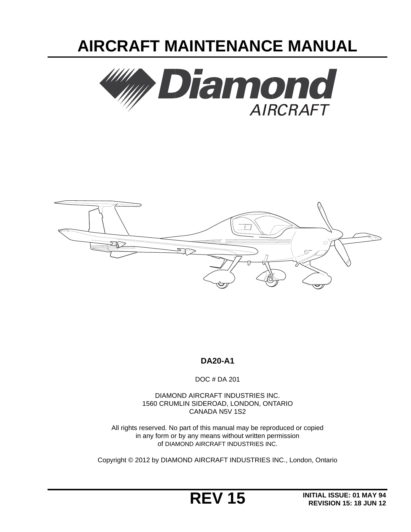
Diamond DA20-A1 Aircraft Maintenance Manual Revision 15 (DA201 AMM) PDF Download β€” PDF page 1 preview
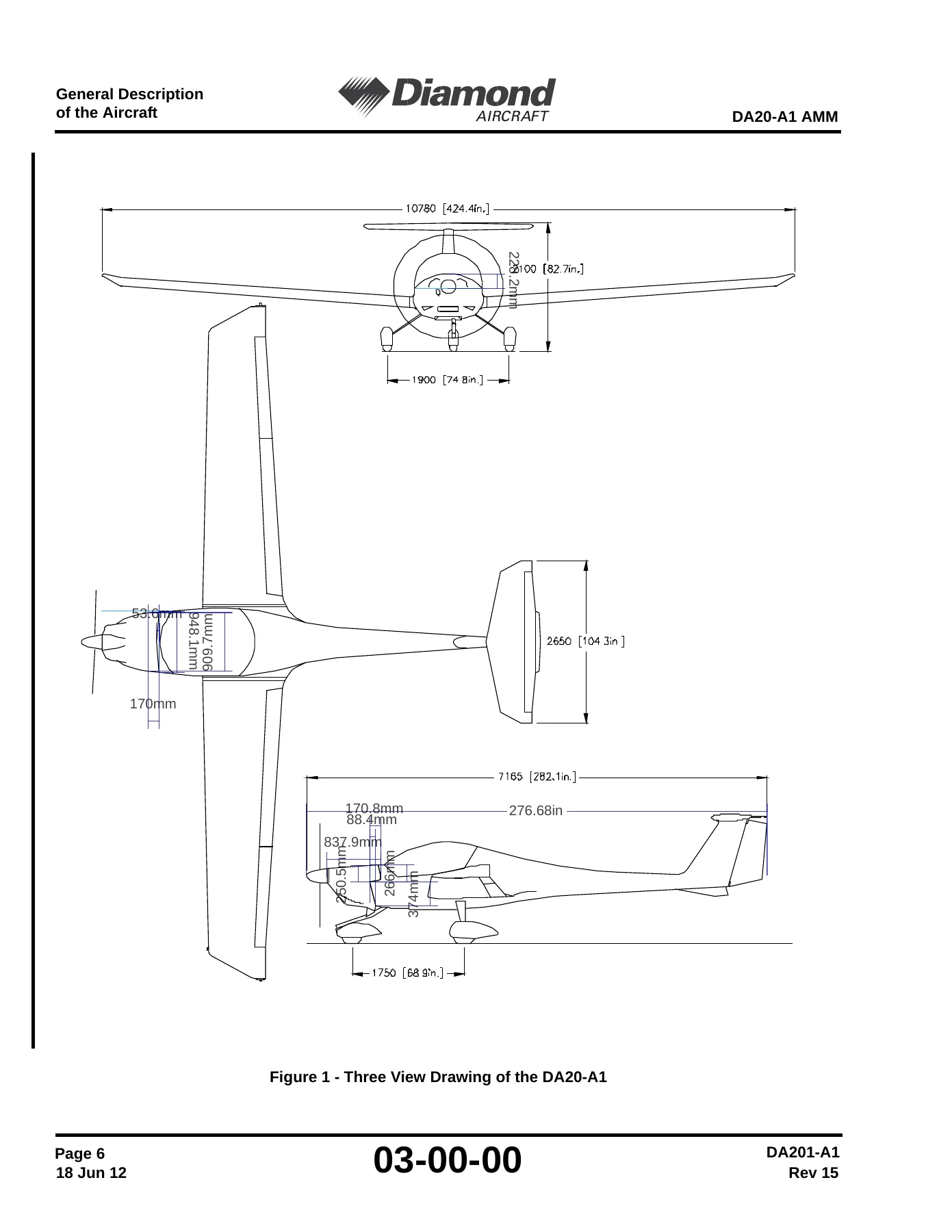
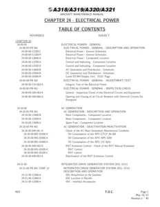
Diamond DA20-A1 Aircraft Maintenance Manual Revision 15 (DA201 AMM) PDF Download β€” PDF page 50 preview
Diamond DA20-A1 Aircraft Maintenance Manual Revision 15 (DA201 AMM) PDF Download β€” PDF page 356 preview

Instant PDF Delivery

You receive the Diamond DA20-A1 Aircraft Maintenance Manual Revision 15 immediately after checkout as a PDF. There is nothing to ship and nothing to wait for. Open it on a laptop, tablet or phone in the hangar or at the bench, search the ATA structure for the system you need, and print the pages you want to work from. The complete DA201 AMM, ready when you are.
Reviews

There are no reviews yet.

Be the first to review “Diamond DA20-A1 Aircraft Maintenance Manual Revision 15 (DA201 AMM) PDF Download”

What Our Customers Say

β˜…β˜…β˜…β˜…β˜… Live reviews from customers
Loading customer reviews...
0
    0
    Your Cart
    Your cart is emptyReturn to Shop
    πŸ›’
    Recently Purchased
    πŸ•’ verified order