★ TRUSTED BY 321,897+ PROFESSIONALS WORLDWIDE
🏢
Trusted Business
Verified & Licensed
🛡️
Virus Free Files
100% Safe Downloads
🔒
Secure Payment
SSL Protected
Instant Delivery
Available Immediately
Sale!

Diamond DA42 L360 Aircraft Maintenance Manual Supplement – D42L-AMM-001 Rev 5 (2012) PDF

Original price was: $49.95.Current price is: $29.95.

Complete maintenance supplement for the Diamond DA42 L360 aircraft converted to Lycoming IO-360/LIO-360 engines. Covers systems modified by STC SA09-54 including power plant, fuel, ignition, electrical, and flight controls. Essential for licensed mechanics and maintenance facilities.

Instant PDF Download
Available immediately
💾
Save to Your Device
Download & keep forever
🛡️
Antivirus Scanned
100% virus-free
🌍
Trusted Worldwide
175,000+ customers

Description

Diamond DA42 L360 Aircraft Maintenance Manual Supplement – D42L-AMM-001 Rev 5 (2012)

File Details

  • Manual Type: Aircraft Maintenance Manual (Supplement)
  • Document Number: D42L-AMM-001
  • Revision: 5
  • Publication Date: October 2012
  • Language: English
  • Page Count: 648 Pages
  • Format: PDF
  • Applicability: Diamond DA42 L360 aircraft modified under TCCA STC No. SA09-54 (FAA STC No. SA02725NY) with Lycoming IO-360-M1A (LH) and LIO-360-M1A (RH) engines.

The Diamond DA42 L360 Aircraft Maintenance Manual Supplement – D42L-AMM-001 Rev 5 (2012) is the definitive maintenance guide for the Lycoming-powered DA42 L360. This supplement provides all necessary instructions for the systems and components altered by the Supplemental Type Certificate (STC) No. SA09-54. It must be used in conjunction with the original DA42 TDI AMM (Document Number 7.02.01) for complete aircraft coverage.

Chapters Covered

This supplement focuses exclusively on the modifications introduced by the Lycoming STC. The following chapters contain data specific to the DA42 L360:

  • Chapter 03-00: General Description of the Aircraft (STC-specific changes)
  • Chapter 04-00: Airworthiness Limitations (Mandatory inspections for new components)
  • Chapter 05-00: Time Limits and Maintenance Checks (25, 50, 100, 200, 1000, 2000-hour checks)
  • Chapter 06-00: Dimensions and Areas (Adjustment report data)
  • Chapter 11-00: Placards and Markings (Interior and exterior placards)
  • Chapter 12-00: Servicing (Fuel, oil, and lubrication schedules)
  • Chapter 20-00: Standard Practices (Torque values for AN, DIN, and LN fasteners)
  • Chapter 24-00: Electrical Power (DC Generation, alternator, voltage regulator, battery)
  • Chapter 25-00: Equipment and Furnishings (Ballast installation)
  • Chapter 27-00: Flight Controls (Rudder, elevator, flaps, variable elevator stop system)
  • Chapter 28-00: Fuel (Distribution, gascolator, booster pump, cross-feed)
  • Chapter 30-00: Ice Protection System (Propeller de-icing)
  • Chapter 31-00: Indicating Systems (G1000 integrated cockpit, GEA 71)
  • Chapter 32-00: Landing Gear (Position and warning micro-switch rigging)
  • Chapter 51-00: Standard Practices – Structures (Electrical bonding system)
  • Chapter 55-00: Stabilizers (Rudder trim seal)
  • Chapter 61-00: Propeller (MT three-blade propeller, governor, accumulator)
  • Chapter 71-00: Power Plant (Engine removal/installation, cowling, mounts, air intakes, drains)
  • Chapter 72-00: Engine (Lycoming IO-360 M1A / LIO-360 M1A description)
  • Chapter 73-00: Engine Fuel and Control (Fuel injector, flow divider, nozzles)
  • Chapter 74-00: Ignition (Dual magnetos, SlickSTART booster, ignition switch)
  • Chapter 75-00: Air (Cooling baffle assembly)
  • Chapter 76-00: Engine Controls (Throttle and mixture Bowden cables)
  • Chapter 77-00: Engine Indicating (Sensors for EGT, CHT, oil pressure, fuel pressure, etc.)
  • Chapter 78-00: Exhaust (Power Flow Systems exhaust, heat exchanger)
  • Chapter 79-00: Oil (Oil cooler, NACA duct)
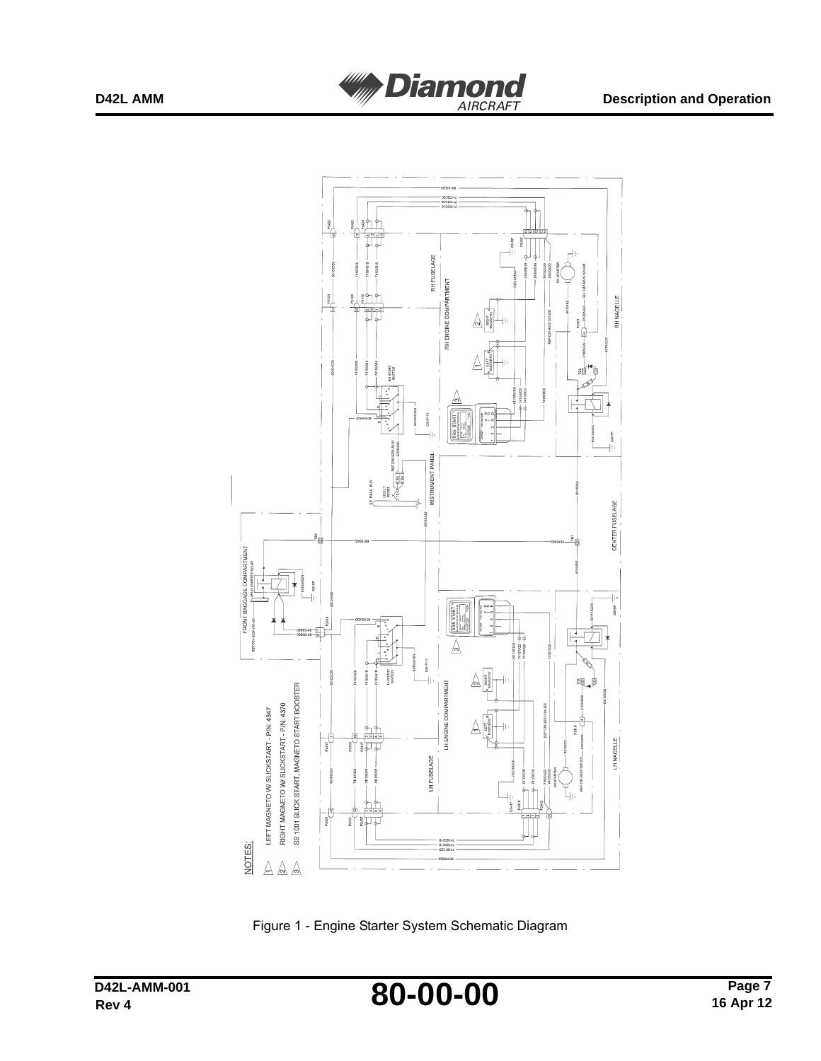
  • Chapter 80-00: Starting (Starter relay, Sky-Tech starter)
  • Chapter 92-00: Wiring Diagrams (Full schematics for the modified electrical system)

Complete PDF Bookmark Tree

Complete Bookmarks

The complete bookmarks in the “Diamond DA42 L360 Aircraft Maintenance Manual Supplement – D42L-AMM-001 Rev 5 (2012) PDF” are as follows:

DA42 L360 – AIRCRAFT MAINTENANCE MANUALp. 1
FRONT MATTERp. 23
Record of Revisionsp. 3
Highlightsp. 5
List of Service Bulletinsp. 7
List of Temporary Revisionsp. 9
List of Effective Pagesp. 11
Table of Contentsp. 23
CHAPTER 01-00 – INTRODUCTIONp. 25
Introductionp. 29
1. Generalp. 29
2. Revision Servicep. 29
3. Warning, Cautions and Notesp. 29
4. Manual Configurationp. 30
A. The ATA iSpec2200 Numbering Systemp. 30
B. Groups of Chaptersp. 31
5. Chapter Configurationp. 32
6. Page Numbering Systemp. 33
7. Figuresp. 33
8. Record of Revisionsp. 33
9. List of Effective Pagesp. 33
CHAPTER 03-00 – GENERAL DESCRIPTION OF THE AIRCRAFTp. 35
General Description of the Aircraftp. 39
1. Generalp. 39
2. Descriptionp. 39
3. Equipment Datap. 39
4. Handling of Identification Datap. 41
CHAPTER 04-00 – AIRWORTHINESS LIMITATIONSp. 43
Airworthiness Limitationsp. 47
1. Airworthiness Limitationsp. 49
A. Certification Maintenance Requirementsp. 49
B. Replacement Requirementsp. 50
2. Continued Airworthinessp. 50
CHAPTER 05-00 – TIME LIMITS AND MAINTENANCE CHECKSp. 51
05-10 – Time Limitsp. 55
1. Generalp. 55
2. Regulatory Authoritiesp. 55
3. Scheduled Maintenance Time Limitsp. 55
4. Component Time Limitsp. 56
A. Maintenance Requirementsp. 56
B. Aircraft Life-Limited Componentsp. 58
C. Life-Limited Componentsp. 58
5. Component TIme Trackingp. 56
05-20 – Scheduled Maintenance Checksp. 59
1. Generalp. 59
2. Maintenance Checklistp. 59
05-20 – Scheduled Maintenance Checks – Maintenance Practicesp. 61
1. Generalp. 61
2. Preparationp. 61
3. Engine Ground Testp. 62
4. Maintenance of Checklist Zonesp. 63
A. Engine Compartmentsp. 63
B. Propellerp. 73
C. Fuselage Nosep. 74
D. Flight Control System in Cabinp. 76
E. Miscellaneous Items in Nacellesp. 76
F. Generalp. 76
5. Engine Ground Test Recordp. 77
CHAPTER 06-00 – DIMENSIONS AND AREASp. 79
Dimensions and Areasp. 83
1. Generalp. 83
2. Dimensionsp. 83
3. Adjustment Reportp. 83
CHAPTER 11-00 – PLACARDS AND MARKINGSp. 87
Description and Operationp. 91
1. Generalp. 91
2. Replace Plastic Placardsp. 91
A. Materialp. 91
B. Replace a Placardp. 91
11-20 Exterior Placards and Markingsp. 93
1. Generalp. 93
11-30 Interior Placards and Markingsp. 95
1. Generalp. 95
2. Descriptionp. 95
Maintenance Practicesp. 101
1. Generalp. 101
2. Replace a Placard Panelp. 101
CHAPTER 12-00 – SERVICINGp. 103
servicingp. 107
1. Generalp. 107
12-10 – Replenishingp. 109
1. Generalp. 109
2. Fuel Systemp. 109
A. Refuelingp. 110
B. Defuelingp. 110
3. Fuel Contamination Testp. 111
A. Equipmentp. 111
B. Fuel Contamination Test Procedurep. 111
4. Engine Oil Systemp. 112
A. Replenish the Oil Systemp. 112
B. Change the Engine Oilp. 113
12-20 – Scheduled Servicingp. 117
1. Generalp. 117
2. Lubrication Schedulep. 118
CHAPTER 20-00 – STANDARD PRACTICESp. 121
20-10 – Standard Practices – Airframep. 125
1. Generalp. 125
2. Bolt and Nut Types Used in the Aircraftp. 125
A. DIN Boltp. 125
B. LN Boltsp. 125
C. AN Boltsp. 126
3. Standard Torque Valuesp. 126
A. AN Fine Threadsp. 126
B. AN Coarse Thread Seriesp. 127
C. DIN and LN Specificationsp. 127
4. Special Torque Valuesp. 127
5. Torque Measurementp. 128
20-70 – Enginesp. 129
1. Generalp. 129
2. Torque Valuesp. 129
3. Special Torque Proceduresp. 131
CHAPTER 24-00 – ELECTRICAL POWERp. 133
Description and Operationp. 137
1. Generalp. 137
2. Electrical System Description and Operationp. 137
A. Power Suppliesp. 137
B. Power Supply Controlp. 138
24-30 – DC Generationp. 143
1. Generalp. 143
2. Description and Operationp. 143
A. Alternatorsp. 143
B. Alternator Switchesp. 143
C. Alternator Current Sensorsp. 143
D. Voltage Regulatorsp. 143
Troubleshootingp. 145
1. Generalp. 145
Maintenance Practicesp. 147
1. Generalp. 147
2. Electrical Safetyp. 147
3. Adjust an Alternator Drive Belt Tensionp. 147
4. Remove/Install an Alternatorp. 149
A. Remove an Alternatorp. 149
B. Install an Alternatorp. 150
5. Remove/Install a Voltage Regulatorp. 151
A. Remove a Voltage Regulatorp. 151
B. Install a Voltage Regulatorp. 152
6. Test an Alternatorp. 152
7. Voltage Regulator (VR2000) Shunt paralleling Paralleling Procedurep. 153
8. Removal/Installation of EMI Filterp. 154
A. Remove the EMI Filterp. 154
B. Install the EMI Filterp. 157
24-31 – Battery Systemsp. 159
1. Generalp. 159
2. Main Battery Description and Operationp. 159
Troubleshootingp. 161
1. Generalp. 161
CHAPTER 25-00 – EQUIPMENT AND FURNISHINGSp. 163
Nose Forward ballast – Description and Operationp. 167
1. Generalp. 167
Nose Forward Ballast – Maintenance Practicesp. 169
1. Generalp. 169
2. Remove/Install the Ballast Plate Assemblies and Clampsp. 169
A. Remove the Ballast Plate Assembly and Clampp. 169
B. Install the Ballast Base Plate Assembly and Clampp. 170
CHAPTER 27-00 – FLIGHT CONTROLSp. 173
27-20 – Flight Controls – Rudderp. 177
1. Generalp. 177
2. Descriptionp. 177
3. Operationp. 178
Maintenance Practicesp. 183
1. Generalp. 183
2. Rudder Control System Test for Correct Range of Movementp. 183
A. Equipmentp. 183
B. Rudder Control Test Procedurep. 183
3. Rudder Control System Adjustmentsp. 184
A. Equipmentp. 184
B. Rudder Control Adjustment Procedurep. 185
4. Remove/Install the Rudder Control Cablesp. 187
A. Equipmentp. 187
B. Remove the Cockpit Rudder Control Cables (Front Cables)p. 187
C. Install the Rudder Control Cables (Front Cables)p. 188
D. Remove the Fuselage Rudder Control Cables (Rear Cables)p. 190
E. Install the Fuselage Rudder Control Cables (Rear Cables)p. 191
5. Rudder System Control Forces Testp. 193
A. Equipmentp. 193
B. Test Procedurep. 193
6. Rudder Control Cable and Yoke Accessp. 194
27-21 – Flight Controls – Rudder Trimp. 203
1. Generalp. 203
Maintenance Practicesp. 205
1. Generalp. 205
2. Rudder Trim Damper Friction Force – Test and Adjustmentp. 205
3. Rudder Trim Rigging Procedurep. 206
A. Equipmentp. 206
B. Rudder Trim Rigging Procedurep. 206
27-30 Flight Controls – Elevatorp. 215
1. Generalp. 215
2. Descriptionp. 215
3. Operationp. 215
Maintenance Practicesp. 217
1. Generalp. 217
2. Elevator Control System Test for Correct Range of Movementp. 217
A. Equipmentp. 217
B. Elevator Control Test Procedurep. 217
3. Elevator Control System Adjustmentsp. 219
A. Equipmentp. 219
B. Elevator Control Adjustment Procedurep. 219
C. Elevator Angle Limits Tablep. 220
4. Remove/Install the Variable Elevator Stop Assemblyp. 220
A. Remove the Variable Elevator Stop Assemblyp. 220
B. Install the Variable Elevator Stop Assemblyp. 221
5. Test/Adjust the Variable Elevator Stopp. 222
A. Equipmentp. 222
B. Variable Elevator Stop Test/Adjustment Procedurep. 222
6. Operational Test of the Variable Elevator Stopp. 223
7. Operational Test of the STICK LIMIT Caution Messagep. 224
8. Rigging Procedure for the Elevator Variable Stop Micro Switchp. 225
9. Elevator Pushrod Accessp. 227
10. Elevator Bellcrank and Lever Accessp. 227
27-50-00 – Flaps – Maintenance Practicesp. 235
1. Generalp. 235
2. Replacement of Flap and Landing Gear Indication Lights Lampp. 235
CHAPTER 28-00 – FUELp. 237
Description and Operationp. 241
1. Generalp. 241
2. Descriptionp. 241
3. Operationp. 241
A. Electrical Boost Pumpp. 241
28-20 – Fuel Distribution – Description and Operationp. 245
1. Generalp. 245
2. Fuel Distribution System Componentsp. 245
A. Fuel Gascolator and Sediment Bowlp. 245
B. Fuel Booster Pumpp. 245
Troubleshootingp. 247
Maintenance Practicesp. 249
1. Generalp. 249
2. Clean/Examine a Fuel Sediment Bowlp. 249
A. Remove and Examine the Fuel Sediment Bowlp. 249
B. Install the Fuel Sediment Bowlp. 250
3. Replace a Gascolator Filterp. 251
4. Remove/Install a Fuel Booster Pumpp. 251
A. Remove a Fuel Booster Pump.p. 251
B. Install the Fuel Booster Pumpp. 253
5. Replace Gascolator Assemblyp. 255
6. Remove/Install the FUEL PUMP Switch (Pre-SB D42L-28-01)p. 256
A. Remove the FUEL PUMP Switchp. 256
B. Install the FUEL PUMP Switchp. 256
7. Remove/Install the Illuminated FUEL PUMP Switch and the Current Monitor (Post-SB D42L-28-01 – Optional Installation)p. 257
A. Remove the Illuminated FUEL PUMP Switch and the Current Monitorp. 257
B. Install the Illuminated FUEL PUMP Switch and the Current Monitorp. 257
8. Functional Test of the Fuel Pumps and the Operational Test of the Fuel Indication Failure Switchp. 258
CHAPTER 30-00 – ICE PROTECTION SYSTEMp. 265
Description and Operationp. 269
1. Generalp. 269
2. Descriptionp. 269
3. Operationp. 270
CHAPTER 31-00 – INDICATING SYSTEMSp. 273
Decription and Operationp. 277
1. Generalp. 277
31-10 – Instrument and Control Panels – Description and Operationp. 279
1. Generalp. 279
2. Instrument Panel Descriptionp. 279
3. Center Console Descriptionp. 280
31-40 – Central Computers – Description and Operations
Central Computer – Maintenance Practicesp. 285
1. Generalp. 285
2. Remove/Install the GEA 71 Processorp. 285
A. Remove the GEA 71 Processorp. 285
B. Install the GEA 71 Processorp. 285
3. G1000 System Software Load Procedurep. 286
A. G1000 Hardware/Software Compatibility Checkp. 286
B. Software Load Procedurep. 286
CHAPTER 32-00 – LANDING GEARp. 289
32-60 – Position and Warning – Description and Operationp. 293
1. Generalp. 293
Position and Warning – Maintnance Practicesp. 295
1. Generalp. 295
2. Rigging Procedure for the Landing Gear Warning Micro Switchp. 295
CHAPTER 51-00 – STANDARD PRACTICES – STRUCTURESp. 301
51-80 – Electrical Bonding – Description and Operationp. 305
1. Generalp. 305
2. Descriptionp. 305
Electrical Bonding – Maintenance Practicesp. 307
1. Generalp. 307
2. Test the Electrical Bonding Systemp. 307
A. Very Low Resistance Measurementsp. 307
B. Low Resistance Measurementsp. 311
C. High Resistance Measurementsp. 311
CHAPTER 55-00 – STABILIZERSp. 313
55-40-00 – Rudder and Trim Tab – Description and Operationp. 317
1. Generalp. 317
Maintenance Practicesp. 319
1. Generalp. 319
2. Remove/Install the Rudder Trim Sealp. 319
A. Remove the Rudder Trim Sealp. 319
B. Install the Rudder Trim Sealp. 319
CHAPTER 61-00 – PROPELLERp. 321
Description and Operationp. 325
1. Generalp. 325
61-10 – Propeller Assembly – Description and Operationp. 327
1. Generalp. 327
2. Description and Operation of MT Propellerp. 327
A. Descriptionp. 327
B. Operationp. 327
Troubleshootingp. 331
1. Generalp. 331
Maintenance Practicesp. 333
1. Generalp. 333
2. Remove/Install the MT Propellerp. 333
A. Remove the Propellerp. 333
B. Install the Propellerp. 334
3. Propeller Blade Tracking Testp. 336
A. Equipmentp. 336
B. Procedurep. 336
61-20 – Propeller Control – Description and Operationp. 339
1. Generalp. 339
2. Description and Operationp. 339
A. Propeller Governorp. 339
B. Hydraulic Accumulatorp. 340
Troubleshootingp. 343
1. Generalp. 343
Propeller Control – Maintenance Practicesp. 345
1. Generalp. 345
2. Remove/Install the Propeller Governorp. 345
A. Remove the Propeller Governorp. 345
B. Install the Propeller Governorp. 346
3. Remove/Install the Propeller Un-Feathering Accumulatorp. 348
A. Remove the Propeller Un-Feathering Accumulatorp. 348
B. Install the Propeller Un-Feathering Accumulatorp. 349
C. Charging the Accumulator with Nitrogenp. 350
4. Functional Test of the Propeller Un-Featheringp. 351
5. Rigging Procedure for Propeller Control Micro Switchp. 353
CHAPTER 71-00 – POWER PLANTp. 361
Description and Operationp. 367
1. Generalp. 367
2. Description and Operationp. 368
A. Cowlingsp. 368
B. Engine Mountsp. 368
C. Electrical Harnessp. 368
D. Air Intakesp. 368
E. Drainsp. 369
3. Engine Specificationp. 369
Troubleshootingp. 373
1. Generalp. 373
Power Plant – Maintenance Practicesp. 375
1. Generalp. 375
2. Remove the Engine (Without the Engine Mount)p. 375
A. Equipmentp. 375
B. Remove the Engine (Without the Engine Mount)p. 376
3. Install the Engine (Without the Engine Mount)p. 382
A. Preparationp. 382
B. Install the Enginep. 383
4. Engine Test – Generalp. 390
A. Equipmentp. 390
B. Preparationp. 390
5. Engine Startingp. 391
6. Measure/Adjust Engine Parametersp. 393
A. Measure Engine Performancep. 393
B. Adjust an Engine Idle Speedp. 396
C. Adjust the Engine Mixture Controlp. 397
7. Engine Shut Downp. 398
8. After Engine Shut Downp. 398
9. Engine Break-In Procedurep. 399
71-10-00 – Cowling – Description and Operationp. 405
1. Generalp. 405
2. Descriptionp. 405
Troubleshootingp. 409
1. Generalp. 409
Cowling – Maintenance Practicesp. 411
1. Generalp. 411
2. Remove/Install the Engine Cowlingsp. 411
A. Remove the Engine Top Cowlingp. 411
B. Remove the Bottom Cowlingp. 412
C. Install the Bottom Cowlingp. 412
D. Install the Engine Top Cowlingp. 413
3. Remove/Install the Winter Kit bafflesp. 414
A. Install the Winter Kit bafflesp. 414
B. Remove the Winter Kit bafflesp. 414
4. Cleaning and Paintingp. 415
A. Clean the Cowlingsp. 415
B. Paint the inside of the Cowlingsp. 415
71-20 – Engine Mounting – Description and Operationp. 417
1. Generalp. 417
Troubleshootingp. 419
1. Generalp. 419
Maintenance Practicesp. 421
1. Generalp. 421
2. Remove/Install an Engine Mountp. 421
A. Equipmentp. 421
B. Remove an Engine Mountp. 421
C. Install an Engine Mountp. 422
71-50 – Electrical Cables in the Engine Compartment – Description and Operationp. 423
1. Generalp. 423
2. Descriptionp. 423
71-60 – Air Intakes – Description and Opeartionp. 427
1. Generalp. 427
2. Descriptionp. 427
A. Alternate Air Assemblyp. 427
B. Air Filter Housingp. 427
C. Air Filterp. 427
D. Alternate Air Valve Operating Cablesp. 427
3. Operationp. 428
Troubleshootingp. 431
1. Generalp. 431
Maintenance Practicesp. 433
1. Generalp. 433
2. Remove/Install an Air Filterp. 433
A. Remove an Air Filterp. 433
B. Install an Air Filterp. 434
3. Remove/Install an Alternate Air Valvep. 434
A. Remove an Alternate Air Valvep. 434
B. Install an Alternate Air Valvep. 435
4. Remove/Install an Alternate Air Control Inner Cablep. 436
A. Remove an Alternate Air Control Forward Inner Cablep. 436
B. Install an Alternate Air Control Forward Inner Cablep. 438
C. Remove an Alternate Air Control Forward Left/Right-Cablep. 439
D. Install an Alternate Air Control Forward Left/Right-Cablep. 440
5. Adjust an Alternate Air Valve Control Cablep. 441
A. Adjust the Alternate Air Valve Forward Control Cablep. 441
B. Adjust a Left/Right Engine Alternate Air Valve Control Cablep. 442
71-70 – Engine Drains – Description and Operationp. 445
1. Generalp. 445
2. Descriptionp. 445
A. Engine Driven Fuel Pumpp. 445
B. Fuel Distributor Drainp. 445
C. Induction Manifold Drainp. 445
3. Operationp. 446
A. Engine Driven Fuel Pump Drainp. 446
(1) Fuel Distributor Drainp. 446
(2) Induction Manifold Drainp. 446
Troubleshootingp. 449
1. Generalp. 449
Maintenance Practicesp. 451
1. Generalp. 451
2. Remove/Install the Engine Driven Fuel Pump Drainp. 451
A. Remove the Engine Driven Fuel Pump Drainp. 451
B. Install the Engine Driven Fuel Pump Drainp. 451
3. Remove/Install Fuel Flow Divider Drainp. 452
A. Remove the Fuel Flow Divider Drainp. 452
B. Install the Fuel Flow Divider Drainp. 452
4. Remove/Install the Induction Manifold Drainp. 453
A. Remove the Induction Manifold Drainp. 453
B. Install the Induction Manifold Drainp. 453
CHAPTER 72-00 – ENGINEp. 455
Description and Operationp. 459
1. Generalp. 459
2. Descriptionp. 459
A. Crankcasep. 459
B. Crankshaftp. 459
C. Camshaftp. 459
D. Connecting Rodsp. 459
E. Flywheelp. 460
F. Cylinder Assemblyp. 460
G. Accessory Housingp. 460
Troubleshootingp. 463
1. Generalp. 463
Engine – Maintenance Practicesp. 465
1. Generalp. 465
2. Cylinder Compression Testp. 465
A. Equipmentp. 465
B. Compression Testp. 465
CHAPTER 73-00 – ENGINE FUEL AND CONTROLp. 469
Description and Operationp. 473
1. Generalp. 473
2. Description and Operationp. 473
A. Engine Driven Fuel Pumpp. 473
B. Fuel Injectorp. 473
C. Fuel Flow Dividerp. 474
D. Injector Nozzlesp. 474
E. Fuel Flow Indicatorp. 474
F. Fuel Pressure Indicatorp. 475
G. Manifold Pressure Indicatorp. 475
H. Air Filter Assemblyp. 475
Troubleshootingp. 477
1. Generalp. 477
Maintenance Practicesp. 479
1. Generalp. 479
2. Remove/Install the Fuel Injectorp. 479
A. Remove the Fuel Injectorp. 479
B. Install the Fuel Injectorp. 480
CHAPTER 74-00 – IGNITIONp. 485
Description and Operationp. 489
1. Generalp. 489
2. Descriptionp. 489
3. Ignition System Componentsp. 490
A. Ignition Switchp. 490
B. Ignition Switch Cablesp. 490
C. Start Boosterp. 491
D. Magnetosp. 491
E. High-Tension Cables (Ignition Harness)p. 491
4. Operationp. 492
A. Ignition Switch to OFF:p. 492
B. Ignition Switch to R:p. 492
C. Ignition Switch to L:p. 492
D. Ignition Switch to BOTH:p. 492
E. Ignition Switch is Set to START:p. 493
Troubleshootingp. 495
1. Generalp. 495
Maintenance Practicesp. 497
1. Generalp. 497
2. Remove/Install an Engine Ignition Switchp. 497
A. Remove an Engine Ignition Switchp. 497
B. Install an Engine Ignition Switchp. 498
3. Remove/Install a Start Booster Control Unitp. 499
A. Remove a Start Booster Control Unitp. 499
B. Install a Start Booster Control Unitp. 500
CHAPTER 75-00 – AIRp. 503
Description and Operationp. 507
1. Generalp. 507
2. Descriptionp. 507
Maintenance Practicesp. 509
1. Generalp. 509
2. Remove/Install a Component of the Baffle Assemblyp. 509
A. Remove the Left Front Bafflep. 509
B. Remove the Left Rear Bafflep. 510
C. Remove the Right Front Bafflep. 512
D. Remove the Right Rear Bafflep. 513
E. Install the Right Rear Bafflep. 514
F. Install the Right Front Bafflep. 516
G. Install the Left Rear Bafflep. 516
H. Install the Left Front Bafflep. 517
CHAPTER 76-00 – ENGINE CONTROLSp. 519
Description and Operationp. 523
1. Generalp. 523
2. Description and Operationp. 523
A. Friction Adjusterp. 523
B. Throttlep. 523
C. Mixture Controlp. 524
Troubleshootingp. 529
1. Generalp. 529
Maintenance Practicesp. 531
1. Generalp. 531
2. Remove/Install a Throttle Control Bowden Cablep. 531
A. Remove a Throttle Control Bowden Cablep. 531
B. Install a Throttle Control Bowden Cablep. 534
3. Remove/Install a Mixture Control Bowden Cablep. 537
A. Remove a Mixture Control Bowden Cablep. 537
B. Install a Mixture Control Bowden Cablep. 540
4. Throttle/Mixture Control Range of Movement Testp. 543
A. Throttle Control Range of Movement Testp. 543
B. Mixture Control Range of Movement Testp. 545
CHAPTER 77-00 – ENGINE INDICATING SYSTEMSp. 549
Description and Operationp. 553
1. Generalp. 553
2. Description and Operationp. 553
77-40 – Engine Indicating System – Description and Operationp. 555
1. Generalp. 555
2. Description and Operationp. 555
A. Transducers and Sensorsp. 556
Troubleshootingp. 557
1. Generalp. 557
Maintenance Practicesp. 559
1. Generalp. 559
2. Replace an Oil Temperature Sensorp. 559
3. Replace the Fuel Flow Sensorp. 561
4. Replace a Cylinder Head Temperature Probep. 563
5. Replace an Exhaust Gas Temperature Probep. 564
6. Replace an Oil Pressure Transducerp. 565
7. Replace a Fuel Pressure Transducerp. 567
8. Replace a Manifold Pressure Transducerp. 569
CHAPTER 78-00 – EXHAUSTp. 579
Description and Operationp. 583
1. Generalp. 583
2. Descriptionp. 583
3. Operationp. 583
Troubleshootingp. 585
1. Generalp. 585
Maintenance Practicesp. 587
1. Generalp. 587
2. Remove/Install an Engine Exhaust Systemp. 587
A. Remove an Engine Exhaust Systemp. 587
B. Install an Engine Exhaust Systemp. 588
C. Inspection of the Exhaust Systemp. 590
D. Pressure Test the Engine Exhaust Systemp. 591
CHAPTER 79-00 – OILp. 593
Description and Operationp. 597
1. Generalp. 597
2. Engine Oil Systemp. 597
3. Oil Cooler NACA Ductp. 597
Troubleshootingp. 599
1. Generalp. 599
Maintenance Practicesp. 601
1. Generalp. 601
2. Remove/Install an Engine Oil Coolerp. 601
A. Remove an Engine Oil Coolerp. 601
B. Install an Oil Coolerp. 602
CHAPTER 80-00 – STARTINGp. 603
Description and Operationp. 607
1. Generalp. 607
2. Descriptionp. 607
A. Elect Master Switchp. 607
B. Ignition Switchesp. 607
C. Start Relaysp. 607
D. Starter Motorp. 608
E. Starter Power ON Captionp. 608
F. Wiresp. 608
3. Operationp. 608
Troubleshootingp. 611
1. Generalp. 611
Maintenance Practicesp. 613
1. Generalp. 613
2. Remove/Install an Engine Start Relayp. 613
A. Remove an Engine Start Relayp. 613
B. Install an Engine Starter Relayp. 614
3. Remove/Install an Engine Starterp. 614
A. Remove an Engine Starterp. 614
B. Install an Engine Starterp. 615
CHAPTER 92-00 – WIRING DIAGRAMSp. 619
Wiring Diagramsp. 623
1. Generalp. 623

This Diamond DA42 L360 Aircraft Maintenance Manual Supplement gives a licensed A&P mechanic or maintenance organization all the data required to maintain the Lycoming IO-360 engine installation. It includes detailed removal/installation steps for major components like the engine, propeller, fuel pumps, alternator, and starter. Step-by-step procedures cover system adjustments, rigging checks, and functional tests. Comprehensive wiring diagrams (Chapter 92) and electrical schematics support accurate troubleshooting of the G1000 avionics and aircraft systems.

The supplement lists all mandatory Service Bulletins and Temporary Revisions applicable to the DA42 L360, ensuring your maintenance records remain current. It provides torque tables for AN, DIN, and LN fasteners, engine-specific torque values, and the airworthiness limitations required by TCCA and FAA regulations (Secs. 43.16 and 91.403). With this manual, you can confidently perform everything from a 25-hour engine check to a 2000-hour structural inspection.

IMAGES PREVIEW

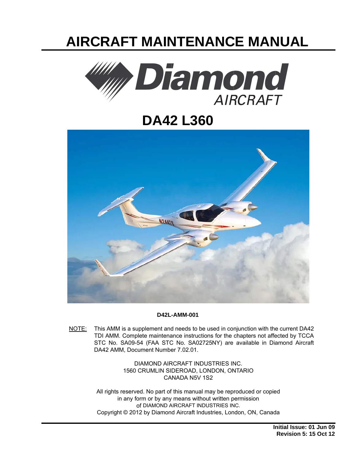
Diamond DA42 L360 Aircraft Maintenance Manual Supplement - D42L-AMM-001 Rev 5 (2012) PDF — PDF page 1 preview
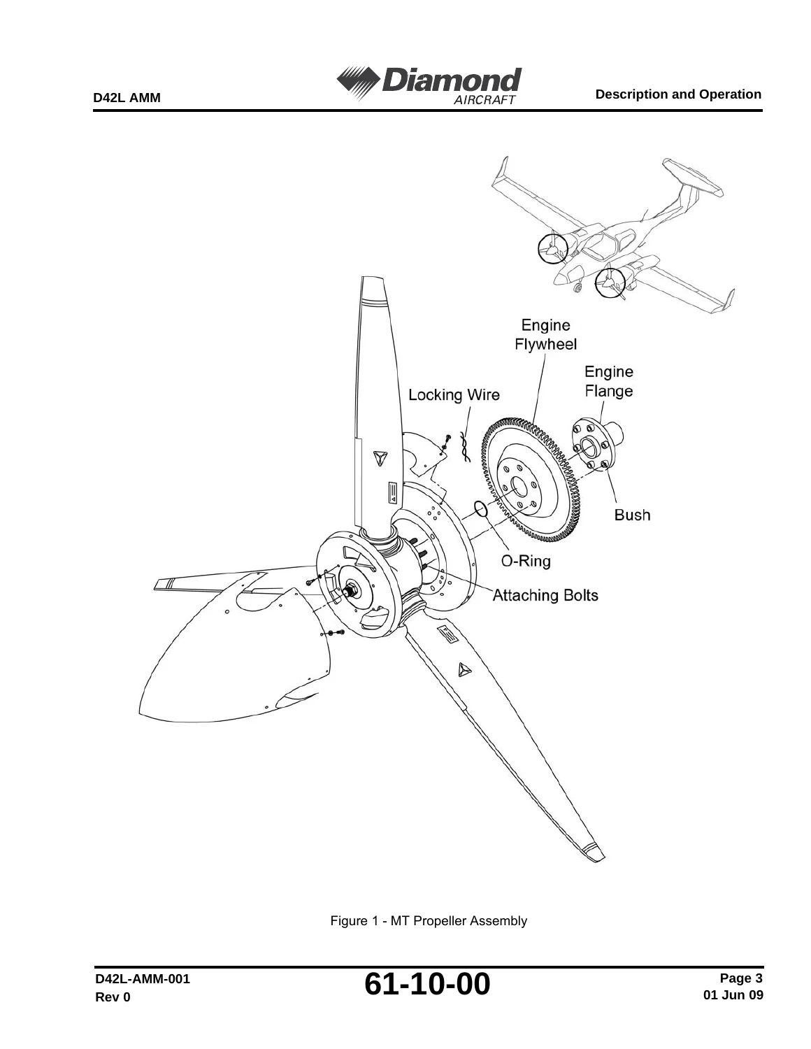
Diamond DA42 L360 Aircraft Maintenance Manual Supplement - D42L-AMM-001 Rev 5 (2012) PDF — PDF page 329 preview
Diamond DA42 L360 Aircraft Maintenance Manual Supplement - D42L-AMM-001 Rev 5 (2012) PDF — PDF page 609 preview

Why This Manual Is Essential

This Diamond DA42 L360 AMM Supplement is not a generic manual; it is the specific document required to maintain the STC-modified aircraft. Without it, you lack the correct procedures for the Lycoming engines, the MT propellers, the revised fuel and ignition systems, and the unique variable elevator stop. This manual protects your aircraft’s airworthiness, ensures compliance with all mandatory inspections, and provides the precision required for safe aircraft operation.

Instant PDF Delivery

Your purchase provides a single, high-quality PDF file exactly as published by Diamond Aircraft Industries. Download it immediately after payment, view it on any computer, tablet, or smartphone, and print specific sections for use in the hangar or workshop. No physical shipping, no waiting, and no handling fees.
Reviews

There are no reviews yet.

Be the first to review “Diamond DA42 L360 Aircraft Maintenance Manual Supplement – D42L-AMM-001 Rev 5 (2012) PDF”

What Our Customers Say

★★★★★ Live reviews from customers
Loading customer reviews...
0
    0
    Your Cart
    Your cart is emptyReturn to Shop
    🛒
    Recently Purchased
    🕒 verified order