
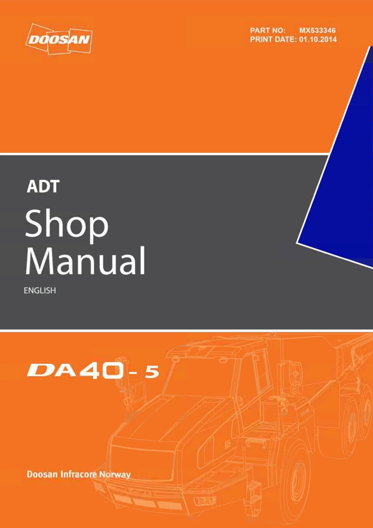
Doosan DA40-5 Articulated Dump Truck Shop Manual 2015 – Complete PDF Service & Repair Documentation
Original price was: $79.95.$49.95Current price is: $49.95.
Full 1070-page Doosan DA40-5 Articulated Dump Truck Shop Manual covering engine, transmission, driveline, hydraulics, electrical, frames, options and error codes. English PDF, serials 821001-up, 841001-up, 820402, 840401.
Description
Doosan DA40-5 Articulated Dump Truck Shop Manual — 2015 English PDF
This is the complete Doosan DA40-5 Articulated Dump Truck Shop Manual — the same in-depth service documentation used for professional repair, overhaul and diagnostics of the DA40-5 ADT. Written for the serial number ranges 821001 – up, 841001 – up, 820402 and 840401, it covers every major system on the machine: the Scania PDE/XPI engine, ZF Ergopower transmission, driveline, lubrication, hydraulics, electrical system, front and rear frames, options and the full error code list.
File Details
- Manual type: Shop Manual (Service & Repair)
- Brand: Doosan Infracore Norway
- Model: DA40-5 Articulated Dump Truck (ADT)
- Language: English
- Page count: 1070
- File format: PDF
- Serial numbers: 821001 – up; 841001 – up; 820402; 840401
- Publication year: 2015
- Publisher: Doosan Infracore Norway AS, N-6440 Elnesvågen, Norway
Chapters Covered
- 0 General
- 1 Engine XPI/PDE
- 2 Transmission
- 3 Driveline
- 4 Lubrication
- 5 Hydraulic
- 6 Electrical system
- 7 Front frame
- 8 Rear frame
- 9 Option
- 10 Error codes list
Chapter 0 – General Instructions
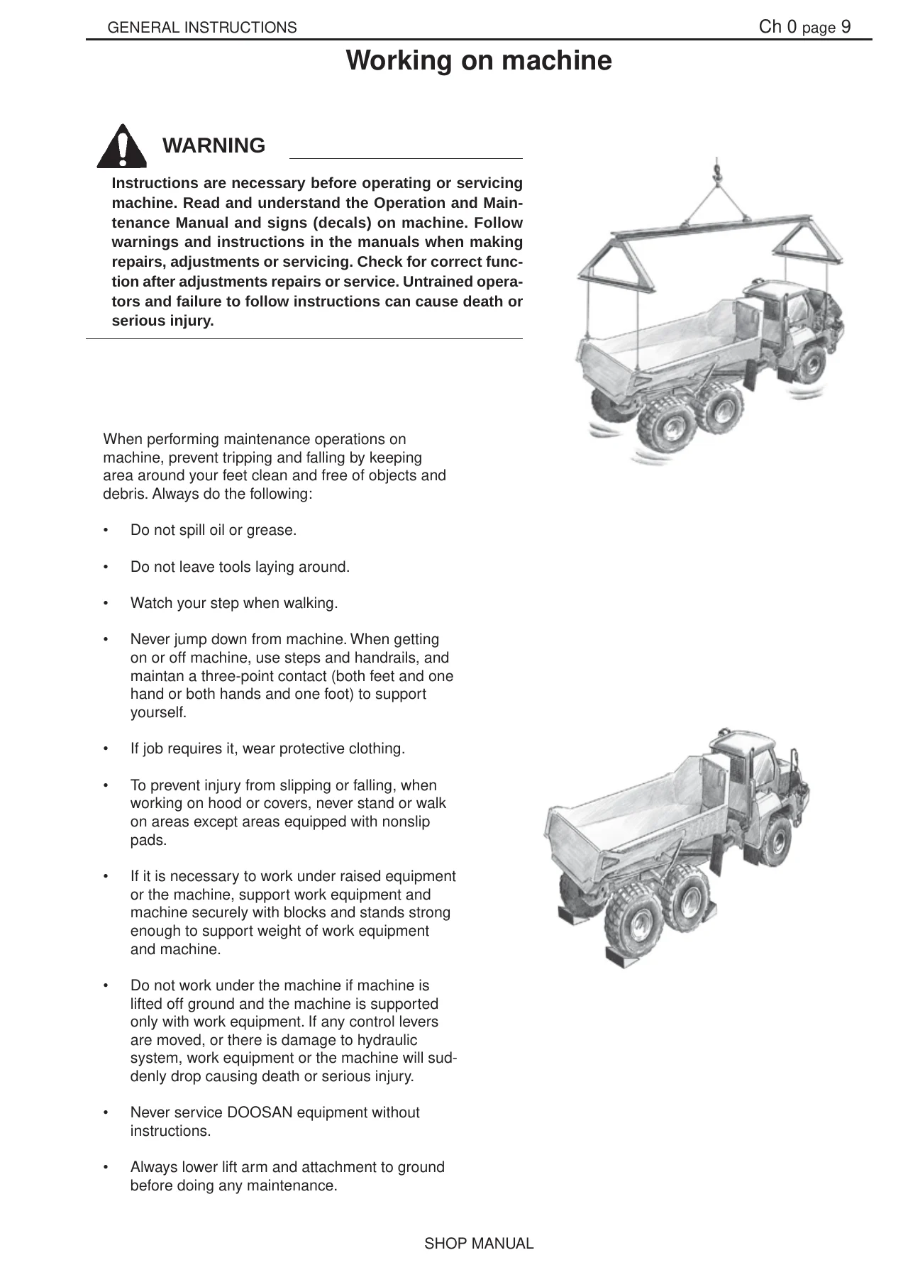
Covers the mandatory torque limit tables for metric and UNC fasteners across quality classes 8.8, 10.9 and 12.9, bolt and nut quality marking, standard dimensions, conversion tables and the full workshop safety program. Includes detailed PPE requirements, vibration injury prevention, injurious noise thresholds, organic solvent handling, fueling and fire precautions, coolant and refrigerant safety, high-pressure liquid and gas hazards, asbestos and lead exposure, battery hazard prevention, safe jacking and heavy-unit handling, and the correct procedures for disassembly and assembly.
Chapter 1 – Engine XPI/PDE
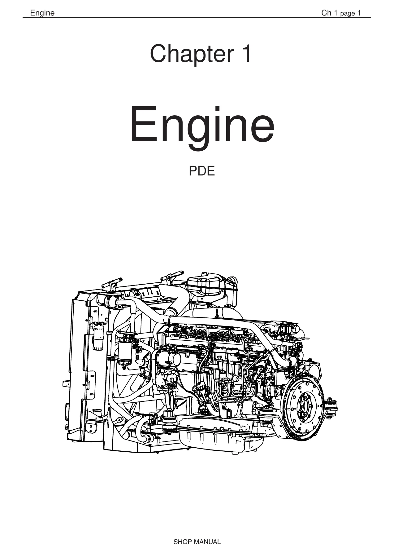
The largest chapter in the manual. Covers engine identification, removal and installation of the complete engine assembly, lifting procedures with the correct lifting eyes and lever block, starting procedure, and the full PDE and XPI fuel systems with schematic diagrams, overflow valve, fuel filter and water-separating prefilter service, bleeding and feed pump renewal. Includes cylinder head tear-down and rebuild, valve mechanism, unit injector removal and fitting, valve and unit injector adjustment (with flywheel readings for DA40 and DA30), turbocharger radial and axial clearance measurement and renewal, pistons and cylinder liners, connecting rods, cylinder block, flywheel and flywheel housing, flexible coupling, timing gear and gear drive, belt drive for coolant pump/generator/AC compressor, crankshaft damper, camshaft and camshaft bearing replacement, crankshaft removal and regrinding data, lubrication system (oil pump, oil cooler, oil filter, centrifugal oil cleaner, oil mist separator), alternator 100 A testing and renewal, brake cooling circulation pump (DA40), cooling fan, cooling system with radiator package, thermostats, coolant pump, and the technical data for DC13 with PDE and DC9 with PDE. The chapter closes with the full troubleshooting guide covering white smoke, black smoke, blue smoke, fuel in oil, oil in coolant, coolant in oil, low/high oil pressure, abnormal wear, vibration, engine speed hunting, delivery pipe fractures, difficult starting, fluid stroke, knocking, high oil/fuel consumption, low compression, low output, overheating, cold running, coolant loss, polluted coolant, high oil/exhaust temperature, low charge air pressure, low fuel pressure, system voltage faults, external leaks and turbocharger breakdown.
Chapter 2 – Transmission
ZF Ergopower L II transmission service. Includes general repair instructions, standard dimension denominations, ZF torque tables, type plate identification and spare parts ordering information, transmission schematics and gear schematics, measuring points and connections with pressure and temperature test ports, clutch calibration, installation sheet, special tools and commercial tools. Removal and disassembly of the transmission from the DA40-5, positioning for disassembly and reassembly, removal and refitting of the LKV axle insert, speed sensor n4-output, solenoid valves of shifting block II and temperature sensors, disassembly and reassembly of shifting block I and speed sensors, separation and attachment of the LKV axle insert, sealing of outputs towards the rear axle and LKV axle insert, shaft seal ring exchange, and the complete transmission assembly procedure with clutch calibration at 100 hours.
Chapter 3 – Driveline
All driveline components that transfer power from the engine through the transmission to each wheel. Covers the front hub, WDB brake housing, wet multi-disc brake installation, wheel head installation and leak testing, the WDB circuit front brake, drive shafts for front and rear frame, front differential and transmission integration, service brakes, parking brake testing, removal of linings, park brake unit disassembly/assembly, initial caliper clearance adjustment, disc inspection, rear differential general function, TK-differential disassembly and assembly, drive pinion disassembly, backlash adjustment, gear-tooth contact patterns, tandem unit removal and assembly, rear wheel hub, cooling circuit rear brake, axle and tandem housing bearings, clearance checking, calculation of tandem bearing, disassembly and assembly of the tandem housing unit, pinion assembly in the tandem housing, and tires.
Chapter 4 – Lubrication System
The Groeneveld Twin automatic greasing system. Covers lubrication system parts (external and internal), greasing cycles, lubrication points on the DA series, grease pressure switch, the 5/2 way valve, the relief valve, minimum level switch, system test (single-test and continuous-test cycles), warning signals, maintenance and regularly checks, bleeding the pump and system, technical data, dimensions of the Twin Pump, and the central lubrication main unit overview.
Chapter 5 – Hydraulic System
The complete hydraulic system — one variable displacement pump feeding steering, accumulators, tilting and cooling fan functions. Includes components, capacities and oil types, hydraulic system main function, system description, components, parts view DA30/DA40, main valve circuit, main valve list of components, system pressure, main valve orifices, main valve spare parts and torques, tilt valve exploded view, hydraulic circuit DA30 and DA40, startup test procedure, main pump description and test block, pump pressure adjusting (low and high), main pump circuit, parts list and exploded view, section drawing, pump shaft disassembly and assembly, steering system, steering master valve (Orbitrol), steering pressure adjustment, steering valve, steering circuit DA30/DA40, steering cylinder and sectional drawing, emergency steering pump, tilt lever, tilting system view, tilt cylinders and sectional drawing, fan system, fan drive motor disassembly, brakes, brake circuit view, service brakes overview, parking brake description and circuit view, accumulators description, correction factor filling table, and accumulator charging.
Chapter 6 – Electrical System
Electrical documentation usage, VCU2 functionality description, wiring contact finding, LCD instrumentation unit with warning lights display and display screen main menu, LCD use description and position reference list, description of the main electrical system including general description, welding precautions on the dump truck, battery hazard prevention, component position, electrical parts view, el.system outside front and rear, electrical equipment inside cab, switch panel, heater unit exploded view and parts list, ignition key switch, air conditioning system components, product final inspection, refrigerant charging, regulation control, pressure reading and troubleshooting, use of the A.T.C., rear frame, DA series functions and parameters (brake/brake charge system, WDB cooling, emergency steering, park brake, low engine oil pressure, low coolant level, clogged air filter, central lubrication pump, charge lamp, body tip system, load weighing, differential lock, cooling fan control, quick warm-up, cool down, alternative engine speed, interior light, retarder and engine brake, emergency stop, fuel heater, A/C compressor control), engine electrical components, EMS S6/S8, electrical cable routing, EMS connection chart, EMS pin list, Engine Management System S8, engine speed and camshaft sensors, wastegate solenoid valve, control unit EMS S8, fuel pressure sensor, fuel inlet metering valve, solenoid valve for XPI injector, transmission electrical components, sensors for hydraulic system, steering valve and main valve electrical connections, parking brake sensor, body float sensor, and the complete electrical chart and circuit diagrams.
Chapter 7 – Front Frame
Front axle suspension, hydraulic gas cylinder disassembly, repair and reassembly, Panhard bar, suspension bearing, cross tube bushings, articulation hinge system, articulation bearing assembly and calculation, articulation hinge service, fenders, mudguards, bonnet, bonnet lock, cab removal, cab ventilation control panel and unit, cab door, door damper cylinder, and steering column.
Chapter 8 – Rear Frame
Dumper body, tilt bearing, and rear frame components including wheels, axles and drive shafts, optional tailgate, tilt cylinders and tailgate operating chain.
Chapter 9 – Option
Optional equipment including automatic tail gate, exhaust body heating system view and assembly, engine heater view and assembly, Webasto heater installation, and telematic system installation with safety, overview, installation procedure, checking functionality and TMS software update.
Chapter 10 – Error Codes List
The complete SPN/FMI error code list in five languages — English, Polish, Spanish, French and German. Covers engine, lubrication, display internal, VCU2 and transmission error codes with the exact SPN and FMI numbers and descriptions.
What This Doosan DA40-5 Shop Manual Enables You to Do
This is not a generic overview — it is the full factory-level service documentation for the DA40-5 ADT. With it you can correctly remove and reinstall the engine assembly, rebuild the cylinder head, adjust valves and unit injectors to the exact cold clearances (0.45 mm intake / 0.70 mm exhaust), diagnose fuel system faults using the PDE and XPI troubleshooting trees, service the ZF Ergopower L II transmission including clutch calibration and shifting block repair, rebuild the wet multi-disc brakes, set the articulation bearing preload, adjust the tilt cylinder and hydraulic pressures (steering 210 bar, tilt 280 bar, accumulators 205 bar), and read the full error code list to pinpoint faults in the VCU2, transmission, engine and lubrication system.
Every torque value, tolerance, clearance, adjustment dimension and diagnostic step is printed exactly as it left the factory — from the M20 engine mounting bracket at 560 Nm to the slotted nut on the wheel hub at 2000–2600 Nm, from the cylinder liner height of 0.20–0.30 mm to the turbocharger radial clearance of 0.198–0.564 mm. Working without these specifications risks premature failure, damaged components and unsafe repairs.
IMAGES PREVIEW
Instant PDF Delivery — No Shipping, No Waiting
The Doosan DA40-5 Articulated Dump Truck Shop Manual is delivered as an instant-download PDF. No physical book to ship, no waiting for the post. Open it on any laptop, tablet or smartphone in the workshop, print the pages you need for the job, and keep the complete manual on file for the life of the machine. Whether you are a fleet workshop, an independent heavy-equipment mechanic, or an owner-operator maintaining your own DA40-5, this is the reference you want open on the bench.
Reviews
There are no reviews yet.